background image


E

POCH

-M1C


U

SER 

M

ANUAL 


Version 1.1 


2607 Colorado Blvd. 

Los Angeles, CA 90041 

USA 

Tel: 323-254-8131 

Fax: 323-254-4928 

www.adrftech.com


Summary of Contents for Epoch-M1C series

Page 1: ...EPOCH M1C USER MANUAL Version 1 1 2607 Colorado Blvd Los Angeles CA 90041 USA Tel 323 254 8131 Fax 323 254 4928 www adrftech com ...

Page 2: ...this document is subject to change without notice Advanced RF Technologies Inc 2002 2006 All rights reserved Please send comments to E Mail info adrftech com Phone 323 254 8131 800 313 9345 Fax 323 254 4928 Address Advanced RF Technologies Inc Attention Technical Publications Department 2607 Colorado Blvd Suite 100 Los Angeles CA 90041 USA www adrftech com ...

Page 3: ... 1 Repeater Setup 12 2 User Manual V1 0 using Epoch M1C Software 16 2 1 Menu Structure 16 2 1 1 Window Menu 16 2 1 2 Status Menu 17 2 1 3 Control Menu 18 2 1 3 1 General Setting Window 18 2 1 3 2 Alarm Setting Window 20 2 1 4 Install Menu 22 2 1 5 System Menu 23 2 1 5 1 Info Window 23 2 1 5 2 Upgrade Window 24 2 2 Using the Epoch M1C Software 25 2 2 1 Changing Parameters 25 2 3 Alarms 26 2 3 1 Gen...

Page 4: ...Installation Problems 31 5 Warranty and Repair Policy 32 5 1 General Warranty 32 5 2 Limitations of Warranty 32 5 3 Limitation of Damages 32 5 4 No Consequential Damages 32 5 5 Additional Limitation on Warranty 32 5 6 Return Material Authorization RMA 33 Appendix A Specifications 34 Appendix B Button Operation 36 ...

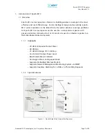
Page 5: ...n Epoch M1C series repeater can be used as a stand alone repeater with passive antennas connected to it or it can also be used as a feeder repeater to a DAS Distributed Antenna System 1 1 1 Highlights 20 dBm Composite Output Power 80 dB Gain 25 dB AGC Range 0 5 dB Step Can Set AGC Output Power Level Band Selectable via Software Can Support Non Contiguous Bands Supports Embedded Wireless Modem Supp...

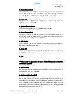
Page 6: ...g towards the BTS 5 VFD Display In this display you are able to view the repeater vitals in each link e g RSS Gain Output Power Alarms 6 Alarm LED If there is an alarm the Alarm LED will be lit Red If there is no alarm the LED will not be lit 7 VFD VFD stands for Vacuum Fluorescent Display Please refer to Appendix B for more detailed information on how the VFD button operates 8 USB Interface For m...

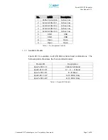
Page 7: ...ve Low 5 External Alarm 4 Active Low 6 GND GND 7 GND GND 8 Open Open 9 Open Open 1 1 3 Available Models Epoch M1C is available in all 850 MHz cellular band combinations The following table illustrates the four standard models Product ID Description Epoch M1C FF Cellular Full Band Epoch M1C AF A A A Band Epoch M1C BF B B Band Epoch M1C AP A 10 MHz Only Epoch M1C BP B 10 MHz Only Table 1 Pin Assignm...

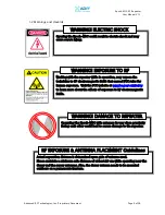
Page 8: ...e RF EXPOSURE ANTENNA PLACEMENT Guidelines Operating the Epoch M1C with antennas in very close proximity facing each other could lead to severe damage to the repeater WARNING DAMAGE TO REPEATER Working with the repeater while in operation may expose the technician to RF electromagnetic fields that exceed FCC rules for human exposure Visit the FCC website at www fcc gov oet rfsafety to learn more a...

Page 9: ...y responsible for compliance could void the user s authority to operate the equipment INFORMATION TO USER This device complies with part 15 of the FCC Rules Operation is subject to the following two conditions 1 This device may not cause harmful interference and 2 This device must accept any interference received including interference that may cause undesired operation NOTE Opening or tampering w...

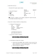
Page 10: ...poch M1C Software Installation and Requirements 1 4 1 Minimum PCS Requirements CPU 200 MHz Memory 32 MB Hard Disk 10 MB Free Space USB Port 1 USB Port CD ROM Drive Compatible Operating System Microsoft Windows 2000 XP 1 4 2 Epoch M1C Software Installation Refer to the Software USB Driver Setup Guide 1 4 3 Initial Startup of Epoch M1C Software a Using the USB cable USB01 that is provided connect on...

Page 11: ...ication has been established b The donor and server antennas are in place c The TX and RX communication status LEDs are lit green and blinking periodically on the Status Menu The TX and RX LEDs should blink every 1 second only in the Status Menu In the Status Menu a blinking green RX LED indicates that the PC is retrieving data from the repeater Epoch M1C Similarly a blinking green TX LED indicate...

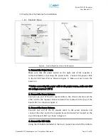
Page 12: ...g the power cable to the power source make sure that the voltage source is 110 V 2 Connect the Donor Antenna Connect one end of the RF coaxial cable to the donor antenna and the other end to the repeater Donor Antenna Port located on the top of the Epoch M1C as shown in Figure 2 3 Connect the Server Antenna Connect one end of the RF coaxial cable to the server antenna and connect the other end to ...

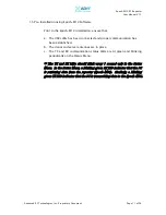
Page 13: ...de of the repeater 6 Launch the Epoch M1C Software Open the Epoch M1C Software You will see the Status Menu For more detailed information on the Epoch M1C Software please refer to Section 2 on page 15 If only one or both of the LEDs are not blinking 1 check the physical USB cable connection or 2 check if the repeater power is turned on 7 Go to the Install Window Now with the blinking TX and RX sta...

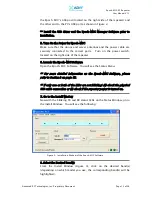
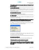
Page 14: ...This installation process will normally take less than a minute Please refer to the Epoch M1C Quick Start Guide for any questions or problems that you may encounter during this installation process If a modem is not connected to the repeater and you click the Install button the following pop up window will appear If you choose to continue with the RF portion only simply click Yes and the installat...

Page 15: ...Epoch M1C RF Repeater User Manual V1 1 Advanced RF Technologies Inc Proprietary Document Page 15 of 38 CONGRATULATIONS The Epoch M1C Installation Process is Complete ...

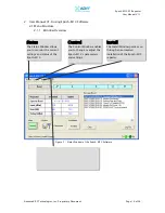
Page 16: ...e 2 1 1 Window Overview Status The Status Window allows you to monitor the current settings and status of the Epoch M1C Control The Control Window enables you to change or adjust the Epoch M1C s parameters and settings Install The Install Window guides you through an automated installation of the Epoch M1C repeater Figure 5 Status Window of the Epoch M1C Software ...

Page 17: ...lor to the corresponding status of the repeater Green for normal operation Yellow for soft fail alarm and Red for hard fail alarm Click on the alarm button for detailed alarm information Message Board The user will be able to see heartbeat messages which are sent out recently In addition the user will also be able to see any alarms that are generated along with messages once the alarms are cleared...

Page 18: ... change the gains in both the links AGC ON must be unchecked If AGC ON is checked and Uplink Tracking ON is unchecked the user can specify the AGC level in the downlink and in the uplink respectively 0 5 dB step 0 to 20 dBm By default the AGC Level is set to 20 dBm in each link Downlink Uplink HPA Mode The HPA mode enables the user to turn the HPA on or off If the HPA is turned off on either link ...

Page 19: ...ll track the down link gain and will be 3 dB less Control Item Action Setting Value Uplink Tracking ON Set Uplink Tracking Mode ON or OFF Uplink Tracking Offset Set Tracking Gain Offset 0 10 dB 0 5 dB step Downlink Uplink Gain The gain of the Epoch M1C is the ratio of the input signal to the output signal The gain may be set in both links The manual gain option is disabled when the AGC ON box is c...

Page 20: ...s only available if the repeater has a wireless modem Periodic Time The Periodic Time is the time interval between Heartbeats only if the repeater has a wireless modem connected to it The default periodic time is 20 minutes The periodic time can be adjusted manually between 1 to 60 minutes Date Time If the repeater doesn t come have a wireless modem you need to set the date and time manually in or...

Page 21: ...Window The threshold RSSI value can also be adjusted manually 0 5 dB step range is shown in Table 5 on page 20 Input Overload A Downlink Uplink Input Overload alarm occurs when the input signal strength to the Epoch M1C exceeds the threshold value refer to the Uplink Downlink Input Overload values in the Alarm Setting window Control Item Action Downlink Uplink Downlink Uplink RSSI Sets Low RSSI Al...

Page 22: ...k on it again SNMP only applicable if a wireless modem is connected to the repeater a Site ID The Site ID is a unique ID for each site and will be provided by the Wireless Provider b Manager IP The Manager IP address will be provided by the Wireless Provider The repeater will send alarms to the Wireless Provider s NOC to the assigned Manager IP address Modem only applicable if a wireless modem is ...

Page 23: ...the use of the Epoch M1C Software during installation refer to Section 1 7 1 on page 11 Repeater Installation starting at number 9 2 1 5 System Menu 2 1 5 1Info Window The Info Window displays the Model Number Serial Number and Firmware Version of the Epoch M1C repeater Contact information is included along with a link to Advanced RF Technologies Inc s URL Figure 10 Info Window of the Epoch M1C So...

Page 24: ...file will be provided by the technical support group from Advanced RF Technologies Inc Once the firmware file has been saved on the PC you would connect the Epoch M1C repeater to the PC via the USB cable provided Click on Open and locate the firmware file and click on Download Once the firmware has been downloaded successfully the following pop up window will appear Figure11 Upgrade Window of the ...

Page 25: ... downlink 2 3 Alarms All the various alarms that are supported by Epoch M1C can be viewed by clicking the Alarm button on the Status Window If a soft or hard fail alarm should occur the corresponding alarm box would be highlighted in yellow or in red respectively In order to find out what is causing the alarm s simply place the mouse cursor over the highlighted yellow or red alarm box Note only ap...

Page 26: ...t has not the same process will continue as mentioned above The alarms can also be viewed on the front panel of the repeater by clicking the VFD button Please refer to Appendix B for more detailed information Epoch M1C also supports AAI Auxiliary Alarm Input Please refer to Section 1 1 2 on Page 6 2 3 1 General Fixed Parameter Alarms Alarm List Soft Fail Hard Fail Comments Over Under Current O O S...

Page 27: ... factory set value a Hard Fail alarm would occur if the downlink over power value was greater than 22 0 dBm 20 dBm is the maximum composite power allowable Similarly a Soft Fail alarm would occur if the downlink over power value was greater than 21 0 dBm but less than 22 0 dBm Vice versa the same example is also applicable in the uplink side 2 4 Default Control Settings 2 4 1 Default General Setti...

Page 28: ...c Proprietary Document Page 28 of 38 2 4 2 Default Alarm Setting Setting Value Control Item Downlink Uplink RSSI 95 dBm 110 dBm Input Overload 35 dBm 35 dBm Heartbeat On Off ON Heartbeat Time 20 minutes Table 10 Default Alarm Parameter Values of the Epoch M1C Software ...

Page 29: ...e in good condition and that the repeater is securely fastened 3 2 Preventive Measures for Optimal Operation 3 2 1 Recommendations Perform the Periodic Inspection Checklist quarterly or semiannually 3 2 2 Precautions Do not operate the repeater with the antennas in extremely close proximity as this may cause damage to the repeater Do not change parameters unless instructed to do so by an authorize...

Page 30: ...e the repeater is either processing or executing a command Wait for a few seconds for the Rx LED to blink periodically Blinking GREEN RED The repeater is not receiving any commands from the software Ensure that the repeater is tuned on and check for proper USB port connection RED RED The USB port can not send or receive data Check if the USB driver has been installed and also verify if the physica...

Page 31: ... Low Isolation or Oscillation Increase the separation between the donor and server antennas by moving the antennas around or by rotating them Downlink Uplink VSWR Alarm Check the cabling because RF signals may be leaking and also verify that the connectors are tightly secured Downlink Uplink Input Power Overload Alarm Add an attenuator after the donor server antenna to reduce the strong donor serv...

Page 32: ...it Advanced RF Technologies Inc warranty applies to repaired or replaced products for the balance of the applicable period of the original warranty or ninety days from the date of shipment of a repaired or replaced product whichever is longer 5 3 Limitation of Damages The liability for any defective product shall in no event exceed the purchase price for the defective product 5 4 No Consequential ...

Page 33: ...ctions on how to return the product An unauthorized return i e one for which an RMA number has not been issued will be returned to you at your expense Authorized returns are to be shipped to the address on the RMA in an approved shipping container You will be given our courier information It is suggested that the original box and packaging materials should be kept if an occasion arises where a def...

Page 34: ...el 3 B B Band Epoch M1C AP Model 4 A 10 MHz Only Sub Band Filtering Epoch M1C BP Model 5 B 10 MHz Only Operating Frequency Programmable Freq Step 10 KHz Frequency Error 0 1 ppm Delay 5 usec Each Direction Input Dynamic Range 35 to 60 dBm Repeater Gain 55 to 80 dB Maximum DL UL Output Power 20 dBm Composite DL AGC Range 25 dB 0 5 dB Step UL AGC Range 25 dB 0 5 dB Step Gain Flatness 1 5 dB 45 dBc Fc...

Page 35: ... Female Dry Contact RS 232 Female Connector Type NMS Control USB Cooling External Convection POWER SPECIFICATIONS PARAMETERS SPECIFICATIONS COMMENTS Main AC Power 100 to 240 VAC AC Frequency 45 to 65 Hz Power Adapter shall comply with UL CE Adaptor Voltage Current 6 VDC 4 5 A Power Consumption 30 Watts ENVIRONMENTAL SPECIFICATIONS PARAMETERS SPECIFICATIONS COMMENTS Operating Temperature 41 F to 11...

Page 36: ...RM Green off POWER VFD ALARM Green off DL IN GAIN OUT 102 80 0 10 If there is no modem hardware the display will be blank If a modem exists but is not connected the display will read DIS UL IN GAIN OUT 102 77 0 10 Downlink Uplink 4 sec BAND MODEM B B CON 4 sec STATUS INSTALLED Band Channel Install Status 4 sec If the repeater is not installed the display will read STATUS NOT INSTALLED POWER VFD AL...

Page 37: ...K RSSI Power Off Initializing POWER VFD ALARM 6 sec 16 sec Booting Time Power On off off POWER VFD ALARM Green Red If the VFD button is pressed the display will come up again Display Cycle POWER VFD ALARM Green Red POWER VFD ALARM Green Red POWER VFD ALARM Green Red 4 sec 4 sec Until the condition clears The VFD display will disappear 30 minutes after VFD button is pressed ...

Page 38: ...ff Initializing POWER VFD ALARM 6 sec 16 sec Booting Time Power On off off POWER VFD ALARM Green Red Display Cycle POWER VFD ALARM Green off POWER VFD ALARM Green Red POWER VFD ALARM Green off POWER VFD ALARM Green Red POWER VFD ALARM Green Red 4 sec 4 sec Alarm Cleared Yes No POWER VFD ALARM Green off Right away The VFD display will disappear 30 minutes after VFD button is pressed If the VFD butt...

Reviews: