background image

IPC-601-SCA

1U e-Server Chassis

Summary of Contents for IPC-601-SCA

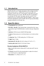
Page 1: ...IPC 601 SCA 1U e Server Chassis ...

Page 2: ...ion provided in this manual is intended to be accurate and reliable However Advantech Co Ltd assumes no responsibility for its use nor for any infringe ments of the right of third parties which may result from such use Acknowledgments IPC 601 and PCA 6102P1V are trademarks of Advantech Co Ltd Note The information in this document is provided for reference only Advantech does not assume any liabili...

Page 3: ...1 Removing the Cover 6 2 2 Installing CPU and Add on Cards 7 2 3 Replacing the Fan 8 2 4 Adding Disk Drives 8 Appendix A Passive Backplane 13 Appendix B Alarm Board 15 Appendix C SCA 2 Backplane 17 Appendix D Exploded Diagram 19 Appendix E Safety Instructions 21 E 1 English 21 E 2 German Wichtige Sicherheishinweise 22 ...

Page 4: ......

Page 5: ...Introduction This chapter gives background informa tion on the IPC 601 SCA Sections include Introduction Specifications Dimensions 1 CHAPTER ...

Page 6: ...mance at the same time 1 2 Specifications Construction Heavy duty steel Disk drive capacity Three optional hot swap hard disc drive space and one slim type CD ROM disk drive and one slim type floppy disk drive Indicators LEDs for power On Off HDD and alarm Controls Momentary power switch and alarm reset switch on front panel Cooling fan Three 7 CFM cooling fans 21 CFM in total Weight 8 kg 17 6 lbs...

Page 7: ...0 Hz auto switch Output voltage 3 3V 20A 5V 32A 12V 12A 5V 0 5 A 12 V 0 5 A 5 Vsb 2 A Minimumload 5V 1 0A MTBF 50 000 Hours 70 load Safety UL CUL CE Environmental specifications Operating temperature 0 45 C 32 113 F Relative humidity 10 95 40 C non condensing Safety UL CE approved CE compliant ...

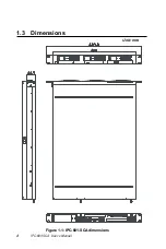
Page 8: ...4 IPC 601 SCA User s Manual 1 3 Dimensions Unit mm Figure 1 1 IPC 601 SCA dimensions ...

Page 9: ...Chapter 2 System Setup 5 CHAPTER 2 System Setup The following procedures are provided to assist you in setting up the IPC 601 SCA ...

Page 10: ...l 2 1 Removing the Cover 1 Unscrew the screws at the rear side of the upper cover 2 Slide the upper cover backwards 3 Lift up the upper cover Please refer to the Figure 2 1 below for illustration Figure 2 1 Upper cover removing ...

Page 11: ...d we suggest to take out the tray from the chassis and install the cards in the tray ouside the chassis Figure 2 2 illustrates the installation of the CPU and add on cards Note Please notice that the SDRAM modules used on the CPU card have height constraints The recommended height is no more than 31 mm Please contact Advantech for recommended vendors Figure 2 2 Installing plug in cards ...

Page 12: ...1 SCA shall be 3 5 1 height SCSI hard disk drives with 80 pin SCA 2 connecotrs In order to install the hard disk drives in the chassis please follow the following procedures 1 Unfasten the dummy HDD trays from the hard disk racks 2 Put hard disk drives in the hard disk racks and fasten them with screws 3 Slide the hard disk racks into the drive bay 2 3 Replacing the Fan The IPC 601 SCA provides th...

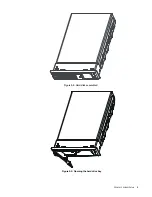
Page 13: ...Chapter 2 System Setup 9 Figure 2 4 Hard disk assembled Figure 2 5 Opening the hard drive bay ...

Page 14: ...10 IPC 601 SCA User s Manual Figure 2 6 Hard drive bay fully open Figure 2 7 Putting the hard drives into the hard drive bays ...

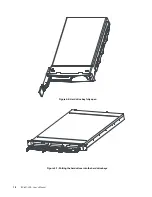
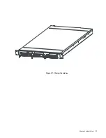
Page 15: ...Chapter 2 System Setup 11 Figure 2 7 Closing the latches ...

Page 16: ...12 IPC 601 SCA User s Manual ...

Page 17: ...hes Connect or Descr i pt i on CN1 Fan 1 connect or CN2 Fan 2 connect or CN3 Fan 3 connect or CN4 Fan 4 connect or CN5 Al ar m boar d connect or J5 3 3 V out put J4 SBC f eat ur econnect or JP1 Enabl e Di sabl eATX powerf unct i on ATX ATX powerconnect or PCIsl ot PCIexpansi on sl ot PI CM G sl ot PI CM G f ul lsi z ed CPU car d ...

Page 18: ...14 IPC 601 SCA User s Manual ...

Page 19: ...cr i pt i on CN1 Al ar m LED connect ort o LED boar d CN2 Fan sensorconnect ort o backpl anePCA 6102P1V CN8 Powerconnect ort o powersuppl y CN10 Temper at ur econnect ort o t em p sensor JP10 5 V Vccconnect ort o LED boar d JP12 Al ar m r esetconnect ort o LED boar d ...

Page 20: ...16 IPC 601 SCA User s Manual ...

Page 21: ...i r c s e D 1 N C A N 2 N C D D H I S C S r o t a c i d n i e v i t c a 3 N C I S C S n i p 8 6 o t r o t c e n n o c t s o h 4 N C r o t c e n n o c r e w o p 5 N C r o t c e n n o c r e w o p 6 N C I S C S 2 A C S D D H 3 D I r o t c e n n o c 7 N C I S C S 2 A C S D D H 1 D I r o t c e n n o c 8 N C I S C S 2 A C S D D H 2 D I r o t c e n n o c ...

Page 22: ...18 IPC 601 SCA User s Manual ...

Page 23: ...IPC 601 SCA User s Manual 19 Appendix D Exploded Diagram ...

Page 24: ...8 0 0 0 1 6 9 6 9 e n a l P k c a B I S C S y s s A 3 1 6 9 2 0 0 0 9 8 6 9 M O R D C m i l S X 4 2 h c r u P 4 1 7 3 0 0 0 0 3 8 6 9 D D F m i l S 5 3 h c r u P 5 1 0 0 1 0 6 2 6 9 1 e t a l p r e d n U s i s s a h C 6 1 0 6 0 1 0 6 2 6 9 1 r a E t n u o M k c a R 7 1 0 0 1 0 6 0 6 9 6 9 d r a o b D E L 8 1 0 0 0 1 0 6 1 7 9 1 e t a l p r o t a c i d n i D E L 9 1 y s s A r e w a r d D D H 1 9 1 ...

Page 25: ...ipment is not used for a long time disconnect it from the power source to avoid damage by transient overvoltage 12 Never pour any liquid into an opening This could cause fire or electrical shock 13 Never open the equipment For safety reasons the equipment should be opened only by qualified service personnel 14 If any of the following situations arises get the equipment checked by service personnel...

Page 26: ...tromnetz trennen Somit wird im Falle einer Überspannung eine Beschädigung vermieden 12 Durch die Lüftungsöffnungen dürfen niemals Gegenstände oder Flüssigkeiten in das Gerät gelangen Dies könnte einen Brand bzw elektrischen Schlag auslösen 13 Öffnen Sie niemals das Gerät Das Gerät darf aus Gründen der elektrischen Sicherheit nur von authorisiertem Servicepersonal geöffnet werden 14 Wenn folgende S...

Reviews: