background image

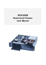
IPC-602

2U 6-slot Industrial 
Rackmount Chassis

User’s Manual

Summary of Contents for IPC-602

Page 1: ...IPC 602 2U 6 slot Industrial Rackmount Chassis User s Manual ...

Page 2: ...nual is intended to be accurate and reliable However Advantech Co Ltd assumes no responsibility for its use nor for any infringements upon the rights of third parties which may result from its use Acknowledgements Intel Pentium 4 and Celeron are trademarks of Intel Corporation IPC 602 PCA 6105P4V PCA 6106P3V PCA 6106P3VX and PCA 6106P4V are trademarks of Advantech Co Ltd All other product names or...

Page 3: ...formance from your products So if you run into technical difficulties we are here to help For the most fre quently asked questions you can easily find answers in your product doc umentation These answers are normally a lot more detailed than the ones we can give over the phone So please consult this manual first If you still cannot find the answer gather all the information or questions that apply...

Page 4: ...re details If you think you have a defective product follow these steps Step 1 Collect all the information about the problem encountered For example type of PC CPU speed Advantech products used other hardware and software used etc Note anything abnormal and list any on screen messages you get when the problem occurs Step 2 Call your dealer and describe the problem Please have your man ual product ...

Page 5: ...ve carefully inspected the IPC 602 mechanically and electrically before shipment It should be free of marks and scratches and in perfect working order upon receipt As you unpack the IPC 602 check it for signs of shipping damage For example damaged box scratches dents etc If it is damaged or it fails to meet the specifications notify our service department or your local sales represen tative immedi...

Page 6: ...IPC 602 User s Manual vi ...

Page 7: ... 9 Figure 2 2 Installing disk drives 9 2 4 Installing Plug in Cards 10 Figure 2 3 Installing plug in cards 10 2 5 Replacing the Fan 11 Figure 2 4 Replacing the fan 11 2 6 Replacing the Filter 11 Figure 2 5 Replacing the filter 12 2 7 Installing the L form holder 12 Figure 2 6 L form holders 12 Appendix A Optional Passive Backplanes 14 A 1 PCA 6105PV4 4 PCI 1 CPU slots 14 A 2 PCA 6106P3V 1 ISA 3 PC...

Page 8: ...AIMB 744 User s Manual viii ...

Page 9: ...1 CHAPTER 1 General Information ...

Page 10: ...orking systems 1 2 Specifications Construction Heavy duty steel Disk drive capacity One 5 25 and two 3 5 drive bays Indicators LEDs for power On Off and HDD Controls Power On and Reset switches on front panel Cooling fan Two 42 CFM fans on front panel with air filters Weight 8 3 kg 18 26 lbs without power supply Dimensions W x D x H 481 2 x 449 5 x 88 mm 19 x 17 7 x 4 Interior paint color Black 2U...

Page 11: ...L CSA CE TÜV 140 000 hours 50 C full load PS 250ATX Z ATX PFC 250 W AC 95 132 V AC 190 264 V Selectable 5 V 27 A 3 3 V 20 A 12 V 13 A 12 V 0 8 A 5 V 0 3 A 5 Vsb 2 A 5 V 1 5 A 12 V 0 3 A UL cUL 60950 3rd CE EN61000 3 2 Class D TUV FCC CSA Nemko CB CCC 100 000 hours 25 C full load PS 400ATX Z ATX PFC 400 W AC 90 264V Full range 5 V 42 A 3 3 V 20 A 12 V 14 A 12 V 1 A 5 V 1 A 5 Vsb 0 75 A 5 V 2 A 12 V...

Page 12: ...IPC 602 User s Manual 4 1 3 Dimensions Figure 1 1 Dimension Diagram unit mm inch ...

Page 13: ...ing wrist strap at all times Place all electronic components on a static dissipative surface or in a static shielded bag when they are not in the chassis Caution The computer is provided with a battery pow ered Real time Clock circuit There is a danger of explosion if battery is incorrectly replaced Replace only with same or equivalent type rec ommended by the manufacturer Discard used batteries a...

Page 14: ...ection against harmful interference when the equipment is oper ated in a commercial environment This equipment generates uses and can radiate radio frequency energy and if not installed and used in accordance with the instruction manual may cause harmful interference to radio communications Operation of this device in a residential area is likely to cause harmful interference in which case the use...

Page 15: ...7 Chapter2 CHAPTER 2 System Setup ...

Page 16: ...procedures are provided to assist you in installing drives and plug in cards into the IPC 602 2 2 Removing the Cover Unscrew the six screws on the front and rear panels then slide the top cover toward the rear chassis and open it See Figure 2 1 below Figure 2 1 Removing the cover ...

Page 17: ...r outer screws which mount the drive bay to the chassis 2 Slide the drive bay backwards to a location where it is not obstructed by the top rim Lift it free from the chassis 3 Remove the front cover of the drive bay and insert the drives into the proper locations in the drive bay 4 Put back the drive bay properly and fasten the screws Figure 2 2 Installing disk drives ...

Page 18: ...acket You can also fix the other edge of the CPU card using the supplied small L form holder 3 If users need to insert other cards on the other side of the backplane please loosen the L form support first After installing the cards also fix them to the card cage by screwing them into the card bracket Then replace the L form support and fasten it 4 After all cards are installed completely put card ...

Page 19: ... 2 4 Replacing the fan 2 6 Replacing the Filter The filter is located next to the lockable door If IPC 602 is under use constantly the filter should be changed about once a month To replace the filter refer to Figure 2 5 below and do the following 1 Open the lockable door 2 Remove the filter by gently pulling the tab and sliding the filter rightwards 3 Slide a new filter in until it snaps into pla...

Page 20: ...602 Chassis to the rack please install the L form holders to both sides of the chassis Please refer to Figure 2 6 and proceed as following steps 1 Find the L form holders and the screws from the accessory pack age 2 Put the holder to the correct location and fasten the screws to the chassis Figure 2 6 L form holders ...

Page 21: ...13 AppendixA Appendix A Optional Passive Backplanes ...

Page 22: ... Connectors Connector Description CPC1 PICMG connectors PCI 1 4 32 bit PCI BUS connectors primary CN2 8 PIN 12V 12V 3 3V 5V 5V GND and 5VSB connector CN1 3 PIN PS_ON GND and 5VSB for ATX power CN3 3 PIN 12V GND and 5V DC power connector KB1 To CPU card K B connector KB3 To front part K B connector ATX1 ATX Power connector ...

Page 23: ...12V 3 GND 13 GND 4 5V 14 PS ON 5 GND 15 GND 6 5V 16 GND 7 GND 17 GND 8 NC 18 5v 9 5VSB 19 5V 10 12V 20 5V CN2 Pin Name 1 5VSB 2 GND 3 GND 4 5V 5 5V 6 3 3V 7 12V 8 12V KB1 KB3 Pin Name 1 KBCLK 2 KB DT 3 NC 4 GND 5 5V PCI Slot ID SEL PCI interrupt pin route INTA INTB INTC INTD PCI1 AD31 INTB INTC INTD INTA PCI2 AD30 INTC INTD INTA INTB PCI3 AD29 INTD INTA INTB INTC PCI4 AD28 INTA INTB INTC INTD ...

Page 24: ...rom CPU card K B connector VKB2 VKB3 KB Out 5 pin external K B connector VAT1 AT power connector 90D VATX1 ATX Power connector 90D HCN1 PS ON Function to CPU card for ATX Power signal 3 pin connector HCN2 8 pin Alarm Board Power connector HCN3 3 pin 5V and 12V Power connector CN2 CN3 CN1 KB1 KB3 D18 1 11 ATX 10 20 12 PG 5V 12 GND P8 P9 5V 5V 160 8 13 61 47 73 28 260 80 32 89 20 32 20 32 18 29 No c...

Page 25: ...V HCN3 Pin Name 1 12V 2 GND 3 5V VATX1 Pin Name 1 3 3V 2 3 3V 3 GND 4 5V 5 GND 6 5V 7 GND 8 NC 9 5VSB 10 12V 11 3 3V 12 12V 13 GND 14 PS ON 15 GND 16 GND 17 GND 18 5V 19 5V 20 5V VAT1 Pin Name 1 NC 2 5V 3 12V 4 12V 5 GND 6 GND 7 GND 8 GND 9 5V 10 5V 11 5V 12 5V PCI Slot ID SEL PCI interrupt pin route INTA INTB INTC INTD PCI1 AD30 INTC INTD INTA INTB PCI2 AD29 INTD INTA INTB INTC PCI3 AD28 INTA INT...

Page 26: ...6 bit ISA Bus connector PPCI1 PPCI4 32 bit PCI Bus connector Primary Group PICMG1 PICMG connector ATX1 ATX Power connector KB1 KB In from CPU card K B connector KB2 KB3 KB Out 5 pin external K B connector CN1 PS ON Function to CPU card for ATX power signal 3 pin CN2 8 pin Alarm Board Power connector CN3 8 pin 5V and 12V FAN connector ...

Page 27: ... 1 KBCLK 2 KBDAT 3 NC 4 KBGND 5 KBVCC ATX1 PIN Name PIN Name 1 3 3V 11 3 3V 2 3 3V 12 12V 3 GND 13 GND 4 5V 14 PS ON 5 GND 15 GND 6 5V 16 GND 7 GND 17 GND 8 NC 18 5V 9 5VSB 19 5V 10 12V 20 5V PCI Slot IDSEL PCI Interrupt Pin Route INT A INT B INT C INT D PPCI1 AD31 INT B INT C INT D INT A PPCI2 AD30 INT C INT D INT A INT B PPCI3 AD29 INT D INT A INT B INT C PPCI4 AD28 INT A INT B INT C INT D ...

Page 28: ...IPC 602 User s Manual 20 ...

Page 29: ...21 AppendixB Appendix B Parts Ordering Guide ...

Page 30: ... 1 5 25 DISK COVER 25 1960000445 1 FRONT PLATE 5 1962650600 1 3 5 DISK COVER 26 1962002810 1 LOCKABLE DOOR 6 1962002760 1 DISK DRIVE HOUSING 27 1759400200 1 SPEAKER 7 1962002740 2 HDD BRACKET 28 1962002700 2 LED LAMP HOLDER 8 9686610603 1 BACKPLANE 29 1994000060 2 LED HOUSING 9 1962002730 1 FAN BRACKET 30 1 HDD 10 1759081200 2 DUAL FAN 31 1962011510 1 PCI CARD BRACKET 11 9692A10000 1 PS 2 K B USB ...

Page 31: ... COMBO 5 25 5 25 compact storage kit with slim 24X CD ROM and a 3 5 drive bay for FDD or HDD 9684000014 3 5 FDD with black bezel 1701400652 HDD cable ATA 66 100 45 cm 20 cm 1750000073 Low profile P4 CPU cooler up to 3 2 GHz 1759214200 Low profile P4 CPU cooler up to 2 8 GHZ Part Number With Power Supply With Backplane Regulation IPC 602P3 00PB Without power supply with AT switch PCA 6106P3V 0B1 No...

Page 32: ...IPC 602 User s Manual 24 ...

Page 33: ...25 AppendixC Appendix C Safety Instructions ...

Page 34: ...g the equipment to the power outlet 9 Position the power cord so that people cannot step on it Do not place anything over the power cord 10 All cautions and warnings on the equipment should be noted 11 If the equipment is not used for a long time disconnect it from the power source to avoid damage by transient over voltage 12 Never pour any liquid into an opening This could cause fire or elec tric...

Page 35: ...ßsteckdose soll nahe dem Gerät angebracht und leicht zugänglich sein 5 Das Gerät ist vor Feuchtigkeit zu schützen 6 Bei der Aufstellung des Gerätes ist auf sicheren Stand zu achten Ein Kippen oder Fallen könnte Verletzungen hervorrufen 7 Die Belüftungsöffnungen dienen zur Luftzirkulation die das Gerät vor überhitzung schützt Sorgen Sie dafür daß diese Öffnungen nicht abge deckt werden 8 Beachten S...

Page 36: ...Gerät nicht der Bedienungsanleitung entsprechend funktion iert oder Sie mit Hilfe dieser Anleitung keine Verbesserung erzielen e Das Gerät ist gefallen und oder das Gehäuse ist beschädigt f Wenn das Gerät deutliche Anzeichen eines Defektes aufweist 15 Bitte lassen Sie das Gerät nicht unbehehrt hinten unter 20 C 4 F oder oben 60 C 140 F weil diesen Temperaturen das Gerät zerstören könten Der arbeit...

Reviews: