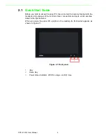
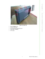
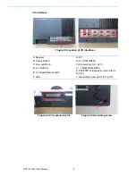
background image

User Manual

PPC-4151W

Intel® Core i processor based 
microcomputer, with 15.6" color 
TFT LCD display

Summary of Contents for PPC-4151W

Page 1: ...User Manual PPC 4151W Intel Core i processor based microcomputer with 15 6 color TFT LCD display ...

Page 2: ...dvantech assumes no liability under the terms of this warranty as a consequence of such events Because of Advantech s high quality control standards and rigorous testing most of our customers never need to use our repair service If an Advantech product is defec tive it will be repaired or replaced at no charge during the warranty period For out of warranty repairs you will be billed according to t...

Page 3: ...ructions may cause harmful inter ference to radio communications However there is no guarantee that interference will not occur in a particular installation If this equipment does cause harmful interfer ence to radio or television reception which can be determined by turning the equip ment off and on the user is encouraged to try to correct the interference by one or more of the following measures...

Page 4: ...pour any liquid into an opening This may cause fire or electrical shock 13 Never open the equipment For safety reasons the equipment should be opened only by qualified service personnel 14 If one of the following situations arises get the equipment checked by service personnel The power cord or plug is damaged Liquid has penetrated into the equipment The equipment has been exposed to moisture The ...

Page 5: ... any components on the CPU card or other cards while the PC is on Disconnect power before making any configuration changes The sudden rush of power as you connect a jumper or install a card may damage sensitive elec tronic components Battery Information Batteries battery packs and accumulators should not be disposed of as unsorted household waste Please use the public collection system to return r...

Page 6: ...PPC 4151W User Manual vi ...

Page 7: ... PCI expansion slot 8 Figure 2 5 Grounding screw 8 2 2 Installation Procedures 9 2 2 1 Connecting the Power Cable 9 Figure 2 6 Connect power cable 9 2 2 2 Connect Keyboard and Mouse 9 2 3 Install Memory Card 10 Figure 2 7 10 Figure 2 8 10 Figure 2 9 10 Figure 2 10 10 Figure 2 11 10 Figure 2 12 10 2 4 Install the HDD 11 Figure 2 13 11 Figure 2 14 11 Figure 2 15 11 Figure 2 16 11 Figure 2 17 11 Figu...

Page 8: ...stallation 17 2 11 Solo Quick Installation 18 2 12 Cradle Installation Description 19 Chapter 3 Jumper Configuration 21 3 1 Jumper Connectors 22 Figure 3 1 PCM 8209 front view 22 3 2 External COM PORT PIN Definition 24 Figure 3 2 COM ports 24 Chapter 4 Software Configuration 27 4 1 Driver Installation Divers 28 4 2 BIOS Setup 28 4 2 1 Enter BIOS 28 4 2 2 Display Brightness Adjustment 29 4 2 3 COM5...

Page 9: ...Chapter 1 1 General Information This chapter gives background information on the PPC 4151W panel PC Sections include Introduction Specifications Dimensions ...

Page 10: ...ons 1 2 1 General Specification Product PPC 4151W LCD Specification 15 6 LCD Display Type 15 6 TFT LCD LED backlight Max Resolution 1366 x 768 Color 16 7M Pixel Pitch 252 per one triad x 252 um Viewing Angle 85 left 85 right 80 top 60 bottom Typ Brightness 300 cd m2 Typ Contrast 500 Typ Backlight Lifecycle 50 000 hours Weight 5 69 Kg 12 55 lb Dimensions 419 7 x 269 x 59 mm 16 52 x 10 59 x 2 32 CPU...

Page 11: ...ype 4 point projected capacitive touchscreen multi touch function is only supported in Win 7 WES7P Win 8 Win 8 1 OS Light Transmission 88 5 Controller USB interface Operation Temperature 0 50 C 32 122 F for SSD 0 45 C 32 113 F for HDD Storage Temperature 20 60 C 4 140 F Relative Temperature 10 95 40 C non condensing Shock 10 G peak acceleration 11 msec duration Vibration 5 500 Hz 1 G RMS EMC BSMI ...

Page 12: ...PPC 4151W User Manual 4 1 3 Dimensions Figure 1 1 PPC 4151W dimensions Note Supports VESA 100 x 100 mm please use M4 screw 6 mm depth maximum Use suitable mounting apparatus to avoid risk of injury ...

Page 13: ...ons include Quick Installation Guide Installation Procedures Install Memory Install HDD Install Mini SATA Install Wireless LAN Install Expansion Card AT ATX Function Switch Grounding Installation Hook Installation Independent Quick Installation ...

Page 14: ...ar with the locations and purposes of the controls drives connectors and ports which are illus trated in the figures below When you place the panel PC upright on the desktop its front panel appears as shown in Figure 2 1 Figure 2 1 Front panel 1 iKey 2 Home Key 3 Power status indicator off S5 orange on S0 blue 1 2 3 ...

Page 15: ...C 4151W User Manual Chapter 2 System Installation Setup Figure 2 2 Side view 1 Quick installation clip 2 Antenna holes two 3 Panel Mounting Bracket holes ten 4 Side USB 2 0 interface 5 CPU cooler 1 2 3 4 5 ...

Page 16: ...ower button H 4 x COM RS232 C Line out Mic in I DC power port 9 32 V D 4 x USB 3 0 J 1 x COM RS422 485 E 2 x Giga Ethernet ports K PCI PCIE x1 Expansion slot refer to Fig 2 4 F VGA L Grounding screw refer to Fig 2 5 Figure 2 4 PCI expansion slot Figure 2 5 Grounding screw A B C E H J G I F D K L ...

Page 17: ... end and follow the procedures below 1 Connect the female end of the power cable to panel PC s DC socket 2 Connect the male end of the power cable to power outlet Figure 2 6 Connect power cable 2 2 2 Connect Keyboard and Mouse Connect the keyboard and mouse to panel PC s I O interfaces 2 2 2 1 Power ON The power button is located in the right bottom side of the panel PC Note Power cable and adapte...

Page 18: ...first Then remove the screws as indicated in the red circle See Fig 2 11 and remove the CPU heatsink Figure 2 7 Figure 2 8 Figure 2 9 Figure 2 10 Note Remove the black and gray thermal grease from the accessary box as indicated in Figure 2 12 Attach the CPU heatsink after the grease is applied Figure 2 11 Figure 2 12 Note CPU cooler pad surface is isolated by anodization treatment to avoid static ...

Page 19: ... the red circles in Fig 2 13 2 Remove the HDD bracket from the reinforced board See Fig 2 14 3 Install the HDD see Fig 2 15 and take out the 4 screws from the accessory box to fix the HDD 4 Lock the HDD bracket and take out the HDD cable from the accessory box and connect it to the mainboard See Fig 2 16 2 18 Figure 2 13 Figure 2 14 Figure 2 15 Figure 2 16 Figure 2 17 Figure 2 18 ...

Page 20: ...less short card you need to take out one hex agonal screw from the accessory box to fix it 2 Take down the antenna bracket in the left top and right top corners of the machine See Fig 2 23 3 Connect the wireless LAN card module cable to the antenna bracket please note the installation direction of cable end and screws cushions See Fig 2 24 4 Lock the bracket and connect the cable to the wireless L...

Page 21: ...13 PPC 4151W User Manual Chapter 2 System Installation Setup Figure 2 23 Figure 2 24 Figure 2 25 Figure 2 26 ...

Page 22: ...nd install the expansion card 2 The original machine provides PCIE riser card PCM 939 see Fig 2 29 and PCI riser card PCM 938 is provided in the accessory box for additional use See Fig 2 30 3 The installation of the expansion card is shown as Fig 2 31 and Fig 2 32 Figure 2 27 Note The maximum dimension of the expansion card is 167 65 mm x 106 7 mm Figure 2 28 Figure 2 29 ...

Page 23: ...System Installation Setup 2 8 AT ATX Function Switch The switch built into the machine lets you choose between AT ATX functions without removing the rear cover Figure 2 30 Figure 2 31 Figure 2 32 Figure 2 33 ATX mode Figure 2 34 AT mode ...

Page 24: ... Installation Loosen the screws remove the plastic cover plug in the grounding cable and then fix the screws See Fig 2 35 Fig 2 38 Figure 2 35 Figure 2 36 Figure 2 37 Figure 2 38 Note The grounding cable is not provided in the accessory box ...

Page 25: ... Installation Follow the figures below Figure 2 39 Hook Installation PPC 4151W Hook Installation Hook Put the machine into the carbinet and prepare the hook Install the hook into the hole to hold the machine as shown above Secure the machine by fastening the screws Screw ...

Page 26: ... install the panel on a wall without assistance by following the panel wall mount installation guide below 1 Loosen the two screws at the bottom see the figure below 2 Push the machine into the gap in the wall and the spring hook will lock the machine into the wall ...

Page 27: ... to Sec tion 2 10 Hook Installation 2 12 Cradle Installation Description Note It is recommended that the mounting thickness is smaller than 2 mm 0 079 according to the quick installation guide For other situations the recommended thickness is less than 6 mm 0 236 Note For the cradle you can choose Advantech product Part No PPC 4150W STANDE Please refer to the included description for the instal la...

Page 28: ...PPC 4151W User Manual 20 ...

Page 29: ...Chapter 3 3 Jumper Configuration Sections include Jumper Connectors Peripheral COM Port DIO Switch and Pin Definitions ...

Page 30: ...9 front view SW1 Panel Resolution Selection Setting Function 1000 for 15 6 LCD 1110 for 21 LCD CN20 COM1 COM2 RI Type Select Description For COM1 COM2 select RI Voltage mode Setting Function 1 3 2 4 default RI 3 5 4 6 5V 7 9 8 10 12V CN15 CN17 CN20 CN45 CN46 SW2 SW1 ...

Page 31: ...uration CN17 clean CMOS Setting Function 1 2 Clear CMOS 2 3 Keep CMOS default SW2 ATX AT Mode Selection Pin Pin Name 1 3 ATX Power default 2 3 AT Power CN15 GPIO Pin Pin Name 1 GND 2 GPIO4 3 GPIO0 4 GPIO5 5 GPIO1 6 GPIO6 7 GPIO2 8 GPIO7 9 GPIO3 10 5V ...

Page 32: ...t COM 3 and COM 4 RS232 COM 5 RS 422 485 COM1 4 Pin 9 is set as RI signal in COM port by default and could be set as 5V 12V output by Jumper Note COM4 doesn t support RING function Pin COM1 COM2 COM3 COM4 1 DCD DCD 2 RXD RXD 3 TXD TXD 4 DTR DTR 5 GND GND 6 DSR DSR 7 RTS RTS 8 CTS CTS 9 RING or 5V 12V output RING Only COM3 COM1 4 COM5 ...

Page 33: ...ing the RS485 auto control function it will automatically drive RTS pin to logic high or low for flow control To make this RS485 auto flow control function work please be noted that the parity and stop bit setting has to be one of the following three settings 1 8 data bits 1 parity bit 1stop bit 2 8 data bits 1 parity bit 2 stop bits 3 8 data bits 2 stop bits Pin 1 2 3 4 5 RS422 TX TX RX RX GND RS...

Page 34: ...PPC 4151W User Manual 26 ...

Page 35: ...Chapter 4 4 Software Configuration Sections include Driver Installation BIOS Setup Program ...

Page 36: ...he accessory box and open it in the system Follow the instructions below to install the drivers The drivers in the accompanying DVD ROM may not be the latest version if needed please find them at http www advantech com 4 2 BIOS Setup 4 2 1 Enter BIOS Start the computer and press the Delete key to enter BIOS Press F4 to save and exit after any configuration or the configuration won t be saved in BI...

Page 37: ... Adjustment 1 Select Brightness Control under Chipset 2 Select Brightness Manual Control under Brightness Control and there will be six options Note If you want to adjust the brightness through AP in the OS it will keep AP configuration mainly and BIOS configuration will not be saved ...

Page 38: ... 4151W User Manual 30 4 2 3 COM5 Mode Selection RS422 485 1 Select Super IO Configuration under Advanced 2 Select Serial Port 5 Configuration and then select the operation mode of COM5 by Serial Port5 Mode ...

Page 39: ...31 PPC 4151W User Manual Chapter 4 Software Configuration 4 2 4 Wake Up by LAN 1 Select ACPI Settings under Advanced 2 Set Wake On By LAN or RI as Enabled ...

Page 40: ...he configuration and exit the OS 4 Right click Computer and click Manage then open Computer Management 5 Click Network adapters in Device Manage then right click and select the needed LAN port then select Properties and open Intel R Ethemet ...

Page 41: ...33 PPC 4151W User Manual Chapter 4 Software Configuration 6 Select Work On Magic Packet Work On Pattern Match and Work On Magic Packet From Power Off State under Power Management ...

Page 42: ...ations are subject to change without notice No part of this publication may be reproduced in any form or by any means electronic photocopying recording or otherwise without prior written permis sion of the publisher All brand and product names are trademarks or registered trademarks of their respective companies Advantech Co Ltd 2014 ...

Reviews: