background image

User Manual

WISE-5000 Series

EtherCAT Slice I/O Modules

Summary of Contents for WISE-5000 Series

Page 1: ...User Manual WISE 5000 Series EtherCAT Slice I O Modules ...

Page 2: ...per installation Advantech assumes no liability under the terms of this warranty as a consequence of such events Because of Advantech s high quality control standards and rigorous testing most of our customers never need to use our repair service If an Advantech product is defec tive it will be repaired or replaced at no charge during the warranty period For out of warranty repairs you will be bil...

Page 3: ...al Fire Pro tection Association work sites are classified into different classes divisions and groups based on hazard considerations This equipment is compliant with the speci fications of Class I Division 2 Groups A B C and D indoor hazards Technical Support and Assistance 1 Visit the Advantech web site at www advantech com support where you can find the latest information about the product 2 Con...

Page 4: ...sient overvoltage 13 Never pour any liquid into an opening This may cause fire or electrical shock 14 Never open the equipment For safety reasons the equipment should be opened only by qualified service personnel 15 If one of the following situations arises get the equipment checked by service personnel 16 The power cord or plug is damaged 17 Liquid has penetrated into the equipment 18 The equipme...

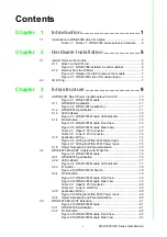
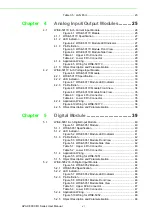
Page 5: ... Figure 3 5 WISE 5001 Module Side View 13 Table 3 1 Upper 4 Pin Connector 14 Table 3 2 Lower 8 Pin Connector 14 3 1 5 Application Wiring 14 Figure 3 6 Wiring for WISE 5001 Digital Input 14 Figure 3 7 Wiring for WISE 5001 Power Input 15 3 1 6 Object Description and Parameterization 15 3 2 WISE 5074 EtherCAT Coupler with ID Switch 16 Figure 3 8 WISE 5074 Module 16 3 2 1 WISE 5074 Specification 16 3 ...

Page 6: ... 4 4 Lower 8 Pin Connector 35 4 2 4 Application Wiring 36 Figure 4 10Wiring for WISE 5017V 36 4 2 5 Object Description and Parameterization 36 Chapter 5 Digital Module 39 5 1 WISE 5051 8 ch Digital Input Module 40 Figure 5 1 WISE 5051 Module 40 5 1 1 WISE 5051 Specification 40 5 1 2 LED Indicator 41 Figure 5 2 WISE 5051 Module LED Indicator 41 5 1 3 Pin Definition 42 Figure 5 3 WISE 5051 Module Fr...

Page 7: ... 4 Application Wiring 57 Figure 5 20Wiring for WISE 5056SO 57 5 4 5 Object Description and Parameterization 57 5 5 WISE 5057 16 ch Sink type Digital Output Module 58 Figure 5 21WISE 5057 Module 58 5 5 1 WISE 5056 Specification 58 5 5 2 LED Indicator 59 Figure 5 22WISE 5057 Module LED Indicator 59 5 5 3 Pin Definition 60 Figure 5 23WISE 5057 Module Front View 60 Figure 5 24WISE 5057 Module Side Vie...

Page 8: ...APAX 5000 I O Series User Manual viii ...

Page 9: ...Chapter 1 1 Introduction ...

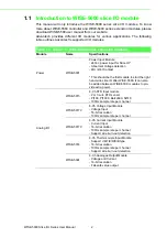
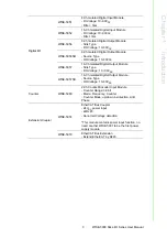
Page 10: ...ge detection 4DI Wet Contact This should be the first module to start the right hand side slice IO after WISE 5580 It can also be added between WISE 50XX modules to pro vide extra power Analog I O WISE 5015 4 Ch RTD Input module 2 or 3 wire RTD sensor Pt100 Pt1000 Balco500 Ni518 100Hz sample rate per channel WISE 5017V 6 Ch Voltage Input Module Voltage Input 16 bit resolution 100Hz sample rate per...

Page 11: ...tage 10 30VDC WISE 5057 16 Ch Isolated Digital Output Module Sink Type DO Voltage 10 30VDC WISE 5057SO 16 Ch Isolated Digital Output Module Source Type DO Voltage 10 30VDC Counter WISE 5080 2 Ch Counter Encoder Input Module Counter Range 32 bit Mode Frequency Counter Counter Mode up down bi direction A B Phase Extension Coupler WISE 5074 EtherCAT Bus Coupler 24VDC power input 2xRJ45 Abnormal Volta...

Page 12: ...WISE 5000 Slice I O Series User Manual 4 ...

Page 13: ...Chapter 2 2 Hardware Installation ...

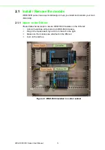
Page 14: ...les easily 2 1 1 Attach on the DIN rail Please follow below steps to secure WISE 5000 modules on the DIN rail 1 Unlock the latches at the bottom of WISE 5000 module 2 Plug in the module each by each from the left to the right 3 Make sure the modules are attached on the DIN rail 4 Lock on the latches Figure 2 1 WISE 5000 installed in control cabinet ...

Page 15: ... 3 WISE 5000 slice I O module design 2 2 I O Wiring WISE 5000 I O modules leverage detachable clamp type terminal blocks Comparing with traditional screw type terminal blocks clamp type terminal blocks can save wiring time and provide better reliability for shock and vibration Follow the procedures below for wiring your WISE 5000 I O module 1 Use the screw driver to press the left notch on the ter...

Page 16: ...APAX 5000 I O Series User Manual 8 ...

Page 17: ...Chapter 3 3 Infrastructure ...

Page 18: ...pply maximum 2A current to the EtherCAT bus to empower the IO modules on the right side WISE 5001 has smart diagnostic function to identify the power error on the external power supply and on internal bus The status can be shown on the LED and on the process data Besides power input function WISE 5001 also equips 4 ch wet contact DI for user to connect to the system event Figure 3 1 WISE 5001 Modu...

Page 19: ...odules follow ing on the right side and isolate from the power on the left side Please refer to the following diagram for the detail Figure 3 2 WISE 5001 Application 3 1 2 WISE 5001 Specification 3 1 2 1 General Certification CE FCC class A Connector Pluggable 4P 8P push in terminal 24 16 AWG Enclosure PC Power Consumption 2W 24VDC Protocol EtherCAT Transmission Rate 100Mbps Distributed Clock Defa...

Page 20: ... 5 Environment Operation Temperature 10 60 C vertical mounted Storage Temperature 40 85 C Relative Humidity 5 95 non condense 3 1 3 LED Indicator Figure 3 3 WISE 5001 Module LED Indicator Figure WISE 5001 Module LED Indicator LED Color Indication Behavior PWR Green ON Power on Run Green ON EtherCAT connection BUS Green ON BUS power on OC RED ON BUS over current OV1 RED ON Vin1 over voltage 30V OV2...

Page 21: ...13 APAX 5000 I O Series User Manual Chapter 3 Infrastructure 3 1 4 Pin Definition Figure 3 4 WISE 5001 Module Front View Figure 3 5 WISE 5001 Module Side View ...

Page 22: ...ation Wiring Figure 3 6 Wiring for WISE 5001 Digital Input Table 3 1 Upper 4 Pin Connector Pin Number Pin Definition 1 V1 2 GND 3 V2 4 FG Table 3 2 Lower 8 Pin Connector Pin Number Pin Definition 1 DI0 2 DI1 3 DI2 4 DI3 5 N A 6 N A 7 DI_COM 8 DI_COM ...

Page 23: ...INT RO 0x00 6000 03 Over_Voltage_2 Voltage 2 28 8V 24 1 2 UINT RO 0x00 6000 04 Under_Voltage_2 Voltage 2 19 2V 24 0 8 UINT RO 0x00 6000 05 Over_Current Current 2A UINT RO 0x00 6000 06 DI0 The digital input channel 0 UINT RO 0x00 6000 07 DI1 The digital input channel 1 UINT RO 0x00 6000 08 DI2 The digital input channel 2 UINT RO 0x00 6000 09 DI3 The digital input channel 3 UINT RO 0x00 6000 11 Volt...

Page 24: ...he power input module supporting 24 VDC dual input for maximum 2A cur rent provides power for the modules which are connected next to the WISE 5074 Figure 3 8 WISE 5074 Module 3 2 1 WISE 5074 Specification 3 2 1 1 General Certification CE FCC class A Connector Pluggable 4P push in terminal 24 16 AWG and 2x RJ45 Enclosure PC Power Consumption 2 5W 24VDC Protocol EtherCAT Transmission Rate 100Mbps D...

Page 25: ...m Around 19 2V Under Voltage Shutdown Around 9V 3 2 1 3 EtherCAT Coupler Function Coupling EtherCAT IO modules to 100BASETX EtherCAT network Cable Ethernet EtherCAT cable min Cat 5 shielded Distance between stations Max 100 m 100BASETX Number of configurable IDs 256 2 x 16 bit ID switch Bus Interface 2 x RJ45 1 x Input 1 x Output 3 2 1 4 Environment Operation Temperature 10 60 C vertical mounted S...

Page 26: ... on Run Green ON EtherCAT connection BUS Green ON BUS power on OC RED ON BUS over current 2A OV1 RED ON Vin1 over voltage 28 8V OV2 RED ON Vin2 over voltage 28 8V UV1 RED ON Vin1 under voltage 19 2V UV2 RED ON Vin2 under voltage 19 2V Switch Number Multiple Range HEX SW1 X1 0 F SW2 X16 0 F Example SW2 SW1 4 C then ID 4 x16 C x1 76 ...

Page 27: ...19 APAX 5000 I O Series User Manual Chapter 3 Infrastructure 3 2 4 Pin Definition Figure 3 11 WISE 5074 Module Front View Figure 3 12 WISE 5074 Module Side View ...

Page 28: ...nal output Index hex Name Meaning Data type Flags Default value 6000 01 Over_Voltage_1 Voltage 1 28 8V 24 1 2 UINT RO 0x00 6000 02 Under_Voltage_1 Voltage 1 19 2V 24 0 8 UINT RO 0x00 6000 03 Over_Voltage_2 Voltage 2 28 8V 24 1 2 UINT RO 0x00 6000 04 Under_Voltage_2 Voltage 2 19 2V 24 0 8 UINT RO 0x00 6000 05 Over_Current Current 2A UINT RO 0x00 6000 06 Device_ID ID Switch UINT RO 0x00 6000 11 Volt...

Page 29: ...nnected to WISE 5074 EtherCAT coupler or any EtherCAT devices to extend EtherCAT network WISE 5079 should be installed at the end of the EtherCAT terminal and the maximum extension distance is 100m Figure 3 14 WISE 5074 Module 3 3 1 WISE 5079 Specification 3 3 1 1 General Certification CE FCC class A Connector 1 x RJ45 Enclosure PC Power Consumption N A Protocol EtherCAT Transmission Rate 100Mbps ...

Page 30: ...herCAT network Cable Ethernet EtherCAT cable min Cat 5 shielded Distance between stations Max 100 m 100BASETX Bus Interface 1 x RJ45 Power from bus N A 3 3 1 3 Environment Operation Temperature 10 60 C vertical mounted Storage Temperature 40 85 C Relative Humidity 5 95 non condense 3 3 2 Pin Definition Figure 3 15 WISE 5079 Module Front View ...

Page 31: ...23 APAX 5000 I O Series User Manual Chapter 3 Infrastructure Figure 3 16 WISE 5079 Module Side View Table 3 5 LAN Port LAN Number LAN Definition 1 EtherCAT signal output ...

Page 32: ...APAX 5000 I O Series User Manual 24 ...

Page 33: ...Chapter 4 4 Analog Input Output Modules ...

Page 34: ... ured using different ranges You can also use CODESYS to configure range type for each channel This module is an extremely cost effective solution for industrial mea surement and monitoring applications The module provides 2000VDC optical isola tion between channels If any high voltage or current damage the channels the whole system other modules and control unit won t be affected cause it is alre...

Page 35: ...nput Type mA Voltage Current Range 20 mA 0 20 mA 4 20 mA Accuracy 0 2 or better of Full Scale Range Current Span Drift 6 ppm C Resolution 16 bit Sampling Rate 100 sample s per channel 4 1 1 3 Protection Isolation Voltage 2000VDC 4 1 1 4 Environment Operation Temperature 10 60 C vertical mounted Storage Temperature 40 85 C Operating Humidity 20 95 RH non condense Storage Humidity 0 95 RH non conden...

Page 36: ...ition Figure 4 3 WISE 5017C Module Front View LED Color Indication Behavior Power Green ON Power on Yellow ON Locating Module Run Error Green ON EtherCAT Connected Blink EtherCAT Connecting OFF EtherCAT Abnormal RED ON Blink System Abnormal OFF No Error ...

Page 37: ... 4 Analog Input Output Modules Figure 4 4 WISE 5017C Module Side View Table 4 1 Upper 4 Pin Connector Pin Number Pin Definition 1 I0 2 I0 3 I1 4 I1 Table 4 2 Lower 8 Pin Connector Pin Number Pin Definition 1 I2 2 I2 3 I3 4 I3 5 I4 6 I4 7 I5 8 I5 ...

Page 38: ...Out Detect whether the input circuit open BOOL RO 0x00 60n0 02 AIn_OverRange Detect whether the input Ohm is under BOOL RO 0x00 60n0 03 AIn_UnderRange Detect whether the input Ohm is over BOOL RO 0x00 60n0 17 AIn Analog input value raw data UINT RO 0x00 Index hex Name Meaning Data type Flags Default value 80n0 01 AIn_EnBurnOut Enable burn out for ch n BOOL RW 1 80n0 17 AIn_Range Type of ch n DT080...

Page 39: ...20 mA 0x180 20 mA 0x181 0 20 mA 0x182 Index hex Name Item Name Default value 0x0801 DT0801EN16 Sampling Rate 10Hz 0 600Hz 1 Index hex Name Item Name Default value 0x0802 DT0802EN16 Burn Out Value Down scale 0 Up scale 1 Index hex Name Meaning Data type Flags Default value F600 01 LocateModule Turn on off Locate LED BOOL RW 0 F600 17 AI_SamplingRate The sampling rate of the module total channel DT0...

Page 40: ... ured using different ranges You can also use CODESYS to configure range type for each channel This module is an extremely cost effective solution for industrial mea surement and monitoring applications The module provides 2500 VDC optical isola tion between channels If any high voltage or current damage the channels the whole system other modules and control unit won t be affected cause it is alr...

Page 41: ...pe V mV mA Voltage Current Range 150 mV 500 mV 1 V 5 V 10 V Accuracy 0 1 or better of Full Scale Range Voltage Span Drift 6 ppm C Resolution 16 bit Sampling Rate 100 sample s per channel 4 2 1 3 Protection Isolation Voltage 2500Vrms 4 2 1 4 Environment Operation Temperature 10 70 C vertical mounted Storage Temperature 40 85 C Operating Humidity 20 95 RH non condensing Storage Humidity 0 95 RH non ...

Page 42: ...ition Figure 4 8 WISE 5017V Module Front View LED Color Indication Behavior Power Green ON Power on Yellow ON Locating Module Run Error Green ON EtherCAT Connected Blink EtherCAT Connecting OFF EtherCAT Abnormal RED ON Blink System Abnormal OFF No Error ...

Page 43: ... 4 Analog Input Output Modules Figure 4 9 WISE 5017V Module Side View Table 4 3 Upper 4 Pin Connector Pin Number Pin Definition 1 V0 2 V0 3 V1 4 V1 Table 4 4 Lower 8 Pin Connector Pin Number Pin Definition 1 V2 2 V2 3 V3 4 V3 5 V4 6 V4 7 V5 8 V5 ...

Page 44: ...ization 4 2 5 1 Input Data of the Module 0x6000 0x6FFF 4 2 5 2 Configuration Data of the Module 0x8000 0x8FFF Index hex Name Meaning Data type Flags Default value 60n0 17 AIn Analog input value raw data UINT RO 0x00 Index hex Name Meaning Data type Flags Default value 80n0 17 AIn_Range Type of ch n DT0800EN16 16 bits RW 0x180 4 20 mA ...

Page 45: ...0x140 5 V 0x142 10 V 0x143 0 150 mV 0x105 0 500 mV 0x106 0 1 V 0x145 0 5 V 0x147 0 10 V 0x148 Index hex Name Item Name Default value 0x0800 DT0800EN16 Calibration Enable Disable 0 Enable 1 Index hex Name Meaning Data type Flags Default value F600 01 LocateModule Turn on off Locate LED BOOL RW 0 F600 17 AI_SamplingRate The sampling rate of the module total channel DT0801E N16 RW 0 10Hz Index hex Na...

Page 46: ...APAX 5000 I O Series User Manual 38 ...

Page 47: ...Chapter 5 5 Digital Module ...

Page 48: ...els If any high voltage or current damage the channels the whole system other modules and control unit won t be affected because it is already isolated Figure 5 1 WISE 5051 Module 5 1 1 WISE 5051 Specification 5 1 1 1 General Certification CE FCC class A Connector Pluggable 4P 8P push in terminal 24 16 AWG Enclosure PC Power Consumption 2W 24VDC Protocol EtherCAT Transmission Rate 100Mbps Distribu...

Page 49: ...logic 0 to 1 4ms From logic 1 to 0 4ms Digital Filter 3ms 5 1 1 3 Protection Isolation Voltage 2 000VDC 5 1 1 4 Environment Operation Temperature 10 60 C vertical mounted Storage Temperature 40 85 C Relative Humidity 5 95 non condense 5 1 2 LED Indicator Figure 5 2 WISE 5051 Module LED Indicator LED Color Indication Behavior Power Green ON Power on Run Green ON EtherCAT connection Green Blink When...

Page 50: ...APAX 5000 I O Series User Manual 42 5 1 3 Pin Definition Figure 5 3 WISE 5051 Module Front View Figure 5 4 WISE 5051 Module Side View ...

Page 51: ...e 5 1 4 Application Wiring Figure 5 5 Wiring for WISE 5051 Table 5 1 Upper 4 Pin Connector Pin Number Pin Definition 1 DI_COM 2 DI_COM 3 Iso GND 4 Iso GND Table 5 2 Lower 8 Pin Connector Pin Number Pin Definition 1 DI0 2 DI1 3 DI2 4 DI3 5 DI4 6 DI5 7 DI6 8 DI7 ...

Page 52: ...nnels the whole system other modules and control unit won t be affected because it is already isolated Figure 5 6 WISE 5052 Module Index hex Name Meaning Data type Flags Default value 3001 01 DI0 Digital Input Channel 0 BOOLEAN RO 0x00 3001 02 DI1 Digital Input Channel 1 BOOLEAN RO 0x00 3001 03 DI2 Digital Input Channel 2 BOOLEAN RO 0x00 3001 04 DI3 Digital Input Channel 3 BOOLEAN RO 0x00 3001 05 ...

Page 53: ...efault not supported LED Indicator PWR RUN 5 2 1 2 Digital Input Channels 16 Digital Input Dry Contact Logic level 1 close to Iso GND Logic level 0 open Wet Contact Rated voltage 24VDC Logic level 1 10 30 VDC and 10 30VDC Logic level 0 3 3VDC Input Delay From logic 0 to 1 4ms From logic 1 to 0 4ms Digital Filter 3ms 5 2 1 3 Protection Isolation Voltage 2 000VDC 5 2 1 4 Environment Operation Temper...

Page 54: ...or 5 2 3 Pin Definition Figure 5 8 WISE 5051 Module Front View LED Color Indication Behavior Power Green ON Power on Run Green ON EtherCAT connection Green Blink When TX RX data in transmission DI0 7 Green ON Dry Wet Logic 1 OFF Dry Wet Logic 0 DI8 15 Yellow ON Dry Wet Logic 1 OFF Dry Wet Logic 0 ...

Page 55: ...5 9 WISE 5051 Module Side View Table 5 3 Upper 6Pin Connector Pin Number Pin Definition 1 DI_COM 2 Iso GND 3 DI0 4 DI1 5 DI2 6 DI3 Table 5 4 Lower 8 Pin Connector Pin Number Pin Definition 1 DI4 2 DI5 3 DI6 4 DI7 5 DI8 6 DI9 7 DI10 8 DI11 9 DI12 10 DI13 11 DI14 12 DI15 ...

Page 56: ...x00 3001 05 DI4 Digital Input Channel 4 BOOLEAN RO 0x00 3001 06 DI5 Digital Input Channel 5 BOOLEAN RO 0x00 3001 07 DI6 Digital Input Channel 6 BOOLEAN RO 0x00 3001 08 DI7 Digital Input Channel 7 BOOLEAN RO 0x00 3002 01 DI8 Digital Input Channel 8 BOOLEAN RO 0x00 3002 02 DI9 Digital Input Channel 9 BOOLEAN RO 0x00 3002 03 DI10 Digital Input Channel 10 BOOLEAN RO 0x00 3002 04 DI11 Digital Input Cha...

Page 57: ...tion between channels If any high voltage or current damage the channels the whole system other modules and control unit won t be affected because it is already isolated Figure 5 11 WISE 5056 Module 5 3 1 WISE 5056 Specification 5 3 1 1 General Certification CE FCC class A Connector Pluggable 4P 8P push in terminal 24 16 AWG Enclosure PC Power Consumption 2W 24VDC Protocol EtherCAT Transmission Ra...

Page 58: ... 0 100us 5 3 1 3 Protection Isolation Voltage 2 000VDC Internal Flyback diode for inductive load 5 3 1 4 Environment Operation Temperature 10 60 C vertical mounted Storage Temperature 40 85 C Relative Humidity 5 95 non condense 5 3 2 LED Indicator Figure 5 12 WISE 5056 Module LED Indicator LED Color Indication Behavior Power Green ON Power on Run Green ON EtherCAT connection Green Blink When TX RX...

Page 59: ...51 APAX 5000 I O Series User Manual Chapter 5 Digital Module 5 3 3 Pin Definition Figure 5 13 WISE 5056 Module Front View Figure 5 14 WISE 5056 Module Side View ...

Page 60: ...lication Wiring Figure 5 15 Wiring for WISE 5056 Table 5 5 Upper 4 Pin Connector Pin Number Pin Definition 1 PCOM 2 PCOM 3 Iso GND 4 Iso GND Table 5 6 Lower 8 Pin Connector Pin Number Pin Definition 1 DO0 2 DO1 3 DO2 4 DO3 5 DO4 6 DO5 7 DO6 8 DO7 ...

Page 61: ...rent damage the channels the whole system other modules and control unit won t be affected because it is already isolated Figure 5 16 WISE 5056SO Module Index hex Name Meaning Data type Flags Default value 3101 01 DO0 Digital Output Channel 0 BOOLEAN RO 0x00 3101 02 DO1 Digital Output Channel 1 BOOLEAN RO 0x00 3101 03 DO2 Digital Output Channel 2 BOOLEAN RO 0x00 3101 04 DO3 Digital Output Channel ...

Page 62: ...s 5 4 1 2 Digital Output Channels 8 Source Type Voltage Rating 10 30VDC Rated Current Output 0 5A per channel at signal 1 Leakage Current 10uA per channel at signal 0 Output Delay From logic level 0 to 1 150us From logic level 1 to 0 2ms 5 4 1 3 Protection Isolation Voltage 2 000VDC Internal Flyback diode for inductive load 5 4 1 4 Environment Operation Temperature 10 60 C vertical mounted Storage...

Page 63: ...igital Module 5 4 3 Pin Definition Figure 5 18 WISE 5056SO Module Front View LED Color Indication Behavior Power Green ON Power on Run Green ON EtherCAT connection Green Blink When TX RX data in transmission DI0 7 Green ON DO turn on OFF DO turn off ...

Page 64: ... Figure 5 19 WISE 5056SO Module Side View Table 5 7 Upper 4 Pin Connector Pin Number Pin Definition 1 VCC 2 VCC 3 Iso GND 4 Iso GND Table 5 8 Lower 8 Pin Connector Pin Number Pin Definition 1 DO0 2 DO1 3 DO2 4 DO3 5 DO4 6 DO5 7 DO6 8 DO7 ...

Page 65: ...Flags Default value 3101 01 DO0 Digital Output Channel 0 BOOLEAN RO 0x00 3101 02 DO1 Digital Output Channel 1 BOOLEAN RO 0x00 3101 03 DO2 Digital Output Channel 2 BOOLEAN RO 0x00 3101 04 DO3 Digital Output Channel 3 BOOLEAN RO 0x00 3101 05 DO4 Digital Output Channel 4 BOOLEAN RO 0x00 3101 06 DO5 Digital Output Channel 5 BOOLEAN RO 0x00 3101 07 DO6 Digital Output Channel 6 BOOLEAN RO 0x00 3101 08 D...

Page 66: ...ween channels If any high voltage or current damage the channels the whole system other modules and control unit won t be affected because it is already isolated Figure 5 21 WISE 5057 Module 5 5 1 WISE 5056 Specification 5 5 1 1 General Certification CE FCC class A Connector Pluggable 6P 12P push in terminal 28 16 AWG Enclosure PC Power Consumption 2 5W 24VDC Protocol EtherCAT Transmission Rate 10...

Page 67: ...5 5 1 3 Protection Isolation Voltage 2 000VDC Internal Flyback diode for inductive load 5 5 1 4 Environment Operation Temperature 10 60 C vertical mounted Storage Temperature 40 85 C Relative Humidity 5 95 non condense 5 5 2 LED Indicator Figure 5 22 WISE 5057 Module LED Indicator LED Color Indication Behavior Power Green ON Power on Run Green ON EtherCAT connection Green Blink When TX RX data in ...

Page 68: ...APAX 5000 I O Series User Manual 60 5 5 3 Pin Definition Figure 5 23 WISE 5057 Module Front View Figure 5 24 WISE 5057 Module Side View ...

Page 69: ... Wiring Figure 5 25 Wiring for WISE 5057 Table 5 9 Upper 6 Pin Connector Pin Number Pin Definition 1 PCOM 2 Iso GND 3 DO1 4 DO2 5 DO3 6 DO4 Table 5 10 Lower 12 Pin Connector Pin Number Pin Definition 1 DO4 2 DO5 3 DO6 4 DO7 5 DO8 6 DO9 7 DO10 8 DO11 9 DO12 10 DO13 11 DO14 12 DO15 ...

Page 70: ...OLEAN RO 0x00 3101 02 DO1 Digital Output Channel 1 BOOLEAN RO 0x00 3101 03 DO2 Digital Output Channel 2 BOOLEAN RO 0x00 3101 04 DO3 Digital Output Channel 3 BOOLEAN RO 0x00 3101 05 DO4 Digital Output Channel 4 BOOLEAN RO 0x00 3101 06 DO5 Digital Output Channel 5 BOOLEAN RO 0x00 3101 07 DO6 Digital Output Channel 6 BOOLEAN RO 0x00 3101 08 DO7 Digital Output Channel 7 BOOLEAN RO 0x00 3102 01 DO8 Dig...

Page 71: ...mption 2 5W 24VDC Protocol EtherCAT Transmission Rate 100Mbps Distributed Clock Default not supported LED Indicator PWR RUN 5 6 1 2 Digital Output Channels 16 Source Type Voltage Rating 10 30VDC Rated Current Output 0 5A per channel at signal 1 Leakage Current 10uA per channel at signal 0 Output Delay From logic level 0 to 1 150us From logic level 1 to 0 2ms 5 6 1 3 Protection Isolation Voltage 2 ...

Page 72: ...40 85 C Relative Humidity 5 95 non condense 5 6 2 LED Indicator Figure 5 27 WISE 5057SO Module LED Indicator LED Color Indication Behavior Power Green ON Power on Run Green ON EtherCAT connection Green Blink When TX RX data in transmission DI0 7 Green ON DO turn on OFF DO turn off DI8 15 Yellow ON DO turn on OFF DO turn off ...

Page 73: ...65 APAX 5000 I O Series User Manual Chapter 5 Digital Module 5 6 3 Pin Definition and Wiring Figure 5 28 WISE 5057SO Module Front View Figure 5 29 WISE 5057SO Module Side View ...

Page 74: ... 5 30 Wiring for WISE 5057SO Table 5 11 Upper 6 Pin Connector Pin Number Pin Definition 1 VCC 2 Iso GND 3 DO1 4 DO2 5 DO3 6 DO4 Table 5 12 Lower 12 Pin Connector Pin Number Pin Definition 1 DO4 2 DO5 3 DO6 4 DO7 5 DO8 6 DO9 7 DO10 8 DO11 9 DO12 10 DO13 11 DO14 12 DO15 ...

Page 75: ...tal Output Channel 4 BOOLEAN RO 0x00 3101 06 DO5 Digital Output Channel 5 BOOLEAN RO 0x00 3101 07 DO6 Digital Output Channel 6 BOOLEAN RO 0x00 3101 08 DO7 Digital Output Channel 7 BOOLEAN RO 0x00 3102 01 DO8 Digital Output Channel 8 BOOLEAN RO 0x00 3102 02 DO9 Digital Output Channel 9 BOOLEAN RO 0x00 3102 03 DO10 Digital Output Channel 10 BOOLEAN RO 0x00 3102 04 DO11 Digital Output Channel 11 BOOL...

Page 76: ...re subject to change without notice No part of this publication may be reproduced in any form or by any means such as electronically by photocopying recording or otherwise without prior written permission from the publisher All brand and product names are trademarks or registered trademarks of their respective companies Advantech Co Ltd 2019 ...

Reviews: