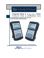
background image


Step Time Domain Reflectometer 


E20/20 Step TDRs and Avionics TDR all models 


Summary of Contents for E20/20

Page 1: ...Step Time Domain Reflectometer E20 20 Step TDRs and Avionics TDR all models ...

Page 2: ...manufacturers This information is believed to be accurate at the time of publication but can not be guaranteed Please consult specific cable manufacturer s website or catalogs and specification sheets for up to date information Acknowledgements Windows XP Windows 7 Windows Vista Excel Word and Power Point are registered trademarks of Microsoft Corp WD 40 is a registered trademark of WD 40 Company ...

Page 3: ... Memory 7 Cable 8 Function Keys 8 Range 8 Zoom 9 Z Scale 9 Cursors 1 2 9 Tone 10 Alpha numeric Keys Backspace key 10 Section 2 Setup and Basic Operation 11 General 11 Step TDR Operation 11 Impedance affects 12 Velocity factor VF 13 Loop resistance and dribble up 13 Menu Navigation Guide 13 Setup Wizard 14 Manual Setups 15 Help 15 Meter 15 Battery Menu 16 Charger Status 17 Date Time Menu 17 Trace 1...

Page 4: ...ance 30 Coax Cable Connections 31 Example Coax Cable Traces 34 Twisted Pair Test Setups 37 Twisted Pair Cable Parameters 38 Impedance 38 Velocity Factor 40 Loop Resistance 41 Twisted Pair Cable Connections and Pair Selection 43 Example Twisted Pair Cable Traces 47 Testing Single Wires in a Harness 52 Testing Power Cables or Other Cables with Large Gauge Conductors 55 Other E20 20 Step TDR Applicat...

Page 5: ...ed Tab 88 Open Trace Plot 89 Chart Information 90 Plot controls 90 TDR Setups Tab 94 Cables Tab 95 Working without the E20 20 TDR connected 96 FTDI Driver Installation 97 Windows 7 97 Preventing Auto Increment of the Serial Port 98 Introduction 98 Overview 99 Choosing a Different COM Port 100 Default Locations for data files supplied with ETDR PC Vision 101 ETDR PC Vision Software Updates 101 Soft...

Page 6: ...tact Us 107 Return Material Authorization RMA Number 107 Appendices Specifications A 1 Twisted Pair Wiring and Connection Guide B 1 Accessories List C 1 TDR LCD and ETDR PC Vision Trace Resolution Tables D 1 Extreme Cold Weather Operations E 1 ...

Page 7: ... Caution should be taken to ensure cables are free of any voltages or static charge prior to connecting the TDR in a potentially explosive atmosphere Operating Precautions 1 The TDRs are designed for recharging NiMH or NiCd AA cells only Do NOT install and attempt to charge Lion cells as overheating or fire may result The resulting damage is not covered under warranty 2 Alkaline cells may be used ...

Page 8: ...inting Warning and Operating Precautions If you have not already done so please read the Explosive Atmosphere Warning and other operating precautions on page v right after the Table of Contents Both the E20 20 TDRs and Avionics TDR operate essentially the same Differences between these TDRs will be pointed out in all the documents where appropriate Most differences are identified in the Appendices...

Page 9: ...re 1 2 for all available connector combinations Ruggedized ABS Plastic Case Quarter VGA Backlit LCD Menu Keys Alpha numeric Keypad and Backspace Key ON OFF Key ENTER Key to accept alpha numeric entries Escape Key Exits menus to Measurement Screen or one level up in menus Changes are saved Figure 1 1 Physical layout is the same for the Avionics TDR ...

Page 10: ...ed E20 20F Network F and RJ 45 Connectors Part Number 6021 5041 CATV Cable List Part Number 6021 5042 Telco Cable List E20 20B Network BNC and RJ 45 Connectors Part Number 6021 5053 VDV RF Cable List Avionics TDR Part Number 6021 5054 TDR with Avionics Cable List Part Number 6021 5154 TDR Kit with Avionics Cable List Figure 1 2 ...

Page 11: ...onds release the ENTER key Note If the TDR s menu cursors stop responding the measurement screen does not show correctly or any other failures to perform correctly occur the TDR s firmware may need to be reset The Soft Reset similar to rebooting a PC function performs several housekeeping functions and restores the TDR to factory default values It will NOT erase saved traces or changes to the Cabl...

Page 12: ...2 when those functions are active The Indicators in the TDR s menus and user literature indicate when to use the appropriate arrow keys Escape Key Unless specified otherwise in the TDR s directions this key is used to exit the menus and either return to the Measurement Screen or back up one menu level Any changes made in the menus will be saved and applied to the measurements or instrument operati...

Page 13: ...s and exit to the Measurement Screen Help Key has two functions 1 If no keypad functions are active all LED s unlit and the TDR is not in a menu the Help key will open its own menu shown in Figure 1 4 Figure 1 4 2 If a function key is active or any menu is open pressing the Help key will provide context sensitive help about the menu feature pointed at by the menu s cursor sub menu or feature being...

Page 14: ...iminating the test leads distance CABLE NULL and activating a noise filter The Trace key s menu is shown in Figure 1 6 Figure 1 6 Memory key opens a menu for saving and recalling traces Saving a trace opens a sub menu for entering the trace name and automatically saves the date time with the trace data Recall opens a list of saved test results Recalling a trace resets the instrument to the recalle...

Page 15: ... shown in Figure 1 8 Figure 1 8 Function Keys General All the function keys activate and de active with one press When active the green LED will light Some function keys can not be operating simultaneously and will automatically de activate other function keys when selected Range Key When active this key uses the keys to control the display ranges Available ranges are Feet Meters 10 2 20 5 50 10 1...

Page 16: ...r a 75 Ohm coax cable if the impedance is reduced to 20 Ohms the display scale will read 65 Ohms to 85 Ohms Cursor 1 Cursor 2 Keys These keys control the use of the Measurement Screen cursors one or both at the same time as follows Cursor 1 only Single cursor in the display and a single CRSR1 data line below the plot Cursor 2 only Single cursor in the display and a single CRSR 2 data line below th...

Page 17: ...gure 1 9 Alpha Numeric Keypad and Backspace Key General The alpha numeric keypad shown in figure 1 10 is for entering values and names The keys work similar to cell phone pads Repeated pressing of the same key will cycle from the number to the next alphabetic character First character above the 1 key is the space The Bcksp key Backspace will delete the last character entered or character just left...

Page 18: ...o basic types Pulse and Step A pulse TDR sends out just one pulse at a time and waits until no more reflection can be received from that pulse to send another pulse This requires adjusting the pulse width and or gain control on those TDR s to clearly see longer cables and faults further away Step TDR s like the E20 20 TDR and Avionics TDR transmit continuous wave sweeps on the cable and interpret ...

Page 19: ...th of a good cable is known as the characteristic impedance Z0 and is designed in at the time of manufacture When measuring with a TDR the readings displayed are the actual impedance Z at each data point along the cable When a cable is good you will see impedance readings that are near or equal to Z0 When a fault occurs the impedance deviates from Z0 Figures 2 2 and 2 3 show the effect of an open ...

Page 20: ...also measures a cable s loop resistance The result is a slight upward slope over distance of the cable as the loop resistance is added to the impedance reading This phenomenon is referred to as Dribble Up More detailed information about impedance velocity factor and loop resistance are contained in Section 3 in this manual AEA Technology s TDR application notes found on the enclosed CD and at www ...

Page 21: ...tering data Set the Z Scale Choose units of measurement feet or meters Set the display range Set the start distance from the end of the TDR Select the input channel Coax or RJ 45 channel A B C or D pair selection Test Lead Null This removes the test lead s length from the measurement Press the Esc key after each selection to move to the next screen and to return to the Measurement Screen after Tes...

Page 22: ...lect the backlight intensity contrast level turn on off keypad beep or to make settings in the BATTERY MENU or DATE TIME menu BACKLIGHT The Backlight feature has four settings OFF LOW MID and HIGH Use the keys to adjust the backlight intensity or turn the backlight off When on the backlight will reduce operating battery hours by 6 10 depending on intensity setting CONTRAST The Contrast will need a...

Page 23: ...on should be in alkaline or none to prevent attempting to charge the cells CAUTION The E20 20 s smart charger is not designed for charging Lion cells Attempting to do so may result in damaged cells damage the instrument and potentially cause a fire This type of damage is not covered under warranty BATTERY MA HR Use this feature to change the mAhrs setting to the re chargeable cell rating installed...

Page 24: ...us state CHARGER STATUS STATUS MEANING LED IDLE No external power applied cells are too hot or cold to accept a charge or BATTERY TYPE is set to Alkaline or None and the charger is off Not lit BATT CHK External power is applied and charger is checking the cells Red blink PRE CHRG Pre Charge Low current charge is being applied to provide initial charge Red solid CHARGING Full charge power is being ...

Page 25: ...he TDR s connector or end of a Test Lead Null if on Press the then use the alpha numeric keypad to enter the start distance desired then press to save and return to the menu MICROFAULT This feature provides two modes of locating small faults on coax cables Use the keys to select one of the following modes OFF TDR presents normal impedance trace on Measurement Screen KINKS ONLY TDR presents an ampl...

Page 26: ... affecting at higher frequencies TEST LEAD NULL ON or OFF Use to turn ON or OFF When ON the stored test lead s length will be removed from the cable s distance measurements The Measurement Screen indicates Null is on when NULL appears below the plot on the left side TEST LEAD NULL Store a Test Lead s Length With the cursor arrow at TEST LEAD NULL press the to measure a test lead and store its leng...

Page 27: ...o the desired cable type and press to select then to return to the Measurement Screen NOTE To move up or down the Cable List faster press and hold the keys or to move by a page at a time use the PICK EDIT LIST EDIT To edit this list select a cable type to replace or an empty cable list slot and press Bcksp Then follow the on screen instructions to enter new description impedance Z0 and Velocity Fa...

Page 28: ...ng VF will be the cable s actual VF Press to accept the modified VF and return to the Measurement Screen NOTE The term Target Distance refers to a distance obtained by actual length measurement in feet or meters cable plat or best estimated distance SAMPLE A CABLE This feature permits measuring a cable s velocity factor It requires knowing the cable s length in feet and inches or meters to make th...

Page 29: ... will re calibrate to the new cable type s impedance Z0 and Velocity Factor VF prior to measuring Measurement Screen and Controls Figure 2 7 Figure 2 7 is an example of the measurement screen The plot displayed has two axis controls The Range key when active used with the keys control the display range The Z Scale key used with the keys control the impedance scale ...

Page 30: ...2 keys used with the keys control the active cursor which in this screen is Cursor 1 only If Cursor 2 is activated both cursors will appear on screen and both cursor LED s will be green The last cursor key pressed will have control of the keys That cursor s data will appear in the top data line and the difference in the measurement to the other cursor will appear in the bottom data line CRSR See F...

Page 31: ...or cable pair If Pocket Toners are selected the TDR will generate the DC voltage required to turn on their tone attachment at the far end of the cable Figure 2 10 NOTES 1 Toner should be used on battery power only Use with the AC charger connected will cause 50 60Hz interfere with the tone frequencies 2 When the Tone feature is active the TDR measurement will not be active 3 When the Tone feature ...

Page 32: ...conductor along with the center conductor Together they can provide a relatively high quality low loss signal path to transport RF signals from a transmitter to an antenna or antenna to a receiver or between transmitter and receiver equipment i e CATV broadband media Having a properly grounded shield around the center conductor also works to counter act on electro magnetic interference EMI aka ing...

Page 33: ...ers published for each brand and type of coax They include conductor size and type shield type cable diameter weight and tables for attenuation at specific frequencies For the use of the TDR we are primarily interested in only three cable parameters Impedance Z0 Velocity Factor VF aka Velocity of Propagation VP or VoP Loop Resistance To obtain the best specifications for the cable being tested vis...

Page 34: ...alue associated with the impedance that should be noted The following table is a list of popular impedances and their common applications Coax Impedance Z0 Common Applications 50 and 52 Ohm Almost all RF communications or radio applications including broadcast land and marine mobile cellular amateur radio HAM etc 62 5 Ohm Specialized broadband applications Example is the old Ethernet thinnet and t...

Page 35: ... display Figure 3 3 Velocity Factor VF This parameter has a number of names all referring to the speed at which an AC signal will travel on a particular cable It s also known as VP or VoP Velocity of Propagation and NVP Nominal Velocity of Propagation The velocity is expressed as a fraction of the speed of light in a vacuum The figure 67 6c indicates a signal on this cable will travel at 67 6 the ...

Page 36: ...ed later in this section under Advanced Features The basic methods for setting a cable s VF is by selecting the cable type from the TDR S s Cable List or entering the cable s parameters manually This will set the TDR s VF All time based measurements of reflections as marked by the cursors will be converted to distance using this VF In figure 3 4 the Cursor 1 is marking the open end of the cable at...

Page 37: ...e TDR s trace to have an upward slope over the length of the conductors known as Dribble up The amount of dribble up is relative to the amount of DC loop resistance that is added to the impedance measurement Cables with relatively small center conductors will have higher loop resistances than cables with larger center conductors As an example 75 Ohm hard line cables which have diameters ranging fr...

Page 38: ...e Twisted Pair The application notes are included on the enclosed E20 20 TDR and Avionics TDR CD or are available on our web site at http www aeatechnology com software application notes Coax Cable Connections In most cases coax cable is connected directly to the TDR or through a connection adapter In some case via a test lead If the test lead and adapters are all well matched this generally resul...

Page 39: ... up figure 3 9 show the proper connection Red clip to center conductor black clip to shield so the center conductor of the cable is feeding the center conductor of the TDR s coax port Additionally the twist in the lead s wires should be maintained as much as possible This will reduce the impedance bump as the signals and reflections pass through the 100 Ohm lead Refer to figure 3 8 s LCD screen an...

Page 40: ...33 Figure 3 8 Figure 3 9 Figure 3 10 ...

Page 41: ... Example Coax Cable Traces The following are examples of good and faulted traces for coax cables Good 50 Ohm Test Lead figure 3 11 Figure 3 11 Good 50 Ohm cable about 53 feet 16 2m figure 3 12 Figure 3 12 ...

Page 42: ...2 Cursor distance between Cursor 1 and 2 or 99 feet 2 inches 30 2m Figure 3 13 Wet 75 Ohm hard line coax figure 3 14 Looking at the trace starting at the left is the test lead connection using F to alligator clips leads to bare coax hence the up bump in impedance at about 2ft 60cm Moving right Cursor 2 is next at 12ft 6 inches 3 8m marking a relatively dry section of the cable Finally Cursor 1 at ...

Page 43: ... 75 Ohm drop from the premise to an aerial tap at 60ft 18 3m figure 3 16 The up bump and arced upward trace at the tap is typical of the electronics in the tap TDR s can t see through electronics so they produce either a gentle roll down or up depending on the impedance from the circuits Figure 3 16 ...

Page 44: ... strict limits on the velocity deviation between pairs in the same jacket referred to as Skew Limits Refer to TIA s 568 C or ISO 11801 testing requirements Connectors for twisted pair cables can also vary depending on application The most popular connectors for horizontal LAN or telephone are the RJ 45 4 pair RJ 12 6 pair and RJ11 2 pair connectors When using TDR designated Network it will include...

Page 45: ...tain the best specifications for the cable being tested visit the manufacturer s web site and search for the cable type and part number to download complete specifications Also pay attention the tolerances for each as this is important for permitted deviations Impedance Impedance specifies the resistance a cable offers to the AC signal being transmitted on the cable It s important the cable s impe...

Page 46: ...is selected or entered it will set the TDR s Z0 to that impedance value The TDR will keep that Z0 value centered if the impedance scale is lowered See figure 3 19 and note the Cable s Z0 is 75 Ohms and the Z Scale is set to 100 Ohms This causes the Z Scale to range from 25 to 125 Ohms to keep the 75 Ohm cable centered For higher Z Scales 200 500 and 1K Ohms the cable s Z0 will be lower in the disp...

Page 47: ...distance to marked events on the cable If the reflections are delayed even slightly in one spot on the cable all the distance measurements after that spot will be off by a factor of that delay Out Side Plant OSP telecommunications cables are built to standards that tightly wrap the pairs inside a shield This makes the VF factor for those pairs remain relatively the same from pair to pair Premise m...

Page 48: ...s between them Loop Resistance Loop resistance is defined as the DC resistance of a pair s two conductors in a cable as measured by an Ohm meter at one end and having a zero Ohm short between the conductors at the opposite end of the cable Specifications for this resistance are normally published for one wire in one direction as the DC resistance over 1000 feet 300m The wires in a pair are always ...

Page 49: ...1 is an example of a Cat 5 cable with good loop resistance Cursor 1 is marking 329ft 2 inches 100m from Cursor 2 and showing 18 1 Ohms difference Specification for this Cat 5 cable was 19 Ohms 5 at 328ft 100m Figure 3 21 NOTES 1 On the 500ft range with 240 plot point on the display the closest positioning of the cursors to 328ft was 329ft 2 inches This is a negligible distance with regards to meas...

Page 50: ...pair selection is made using the Meter menu and INPUT CHANNEL by pressing the to change the input to one of 4 pairs in the RJ45 connector See figure 3 22 Figure 3 22 Each Channel A B C and D represents a pair in the RJ45 connector Refer to Appendix B for a table of input channels to cable pairs depending on the cable s wiring standard When the AEA Technology Telco Test Leads P N 6020 0250 are conn...

Page 51: ...en them will climb rapidly and the display will show a larger impedance bump at the connection point Figure 3 24 Figure 3 25 When a connection requires the clips and or leads be separated be aware of this increase in impedance at the connection point Figure 3 26 shows the same telco test lead connection s trace but with separation between the clips and 2 inches 5cm of wire un twist Figure 3 26 See...

Page 52: ...them via the RJ 45 port s Channels However if using a model without an RJ 45 Port this still permits testing twisted pair cable The connection table shown indicates the use of the included adapters that came with each model of the E20 20 TDR TDR Model Adapters Adapter Part Numbers E20 20N TDR N to BNC adapter and BNC to alligator clips test lead 0070 1190 0070 1221 E20 20F Network CATV F to alliga...

Page 53: ...e 3 28 The example in figure 3 29 is the same connection as figure 3 28 but with the alligator clips and wire pair separated The impedance bump caused by the separation is clearly visible on the LCD Figure 3 29 ...

Page 54: ... is also an antenna Figure 3 30 Same 370ft 112 8m section of cable with a short at the far end Figure 3 31 Note The short also caused and increase in the noise on this pair due to local EMI environment Using the Noise Filter in the Trace menu will eliminate the trace s fuzzy appearance Figure 3 31 Twisted pair with a good splice Figure 3 32 The minor impedance bump is due to the small amount of un...

Page 55: ...in impedance after the right cursor CRSR1 as an example of the drying of the pair Only the distance from the TDR to just before the wet zone can be trusted CRSR2 Figure 3 34 Bridged Taps are an auxiliary connection or drop cable from a main line Figure 3 35 Bridged taps are characterized by a downward dip in impedance to almost half the cable s Z0 This is the results of the TDR receiving reflectio...

Page 56: ...s detected but corrected at a different connection point or splice the result is a re split Both the split and re split can be seen in the trace and distance to each measured A drawing of the split and re spit is shown in figure 3 38 Figure 3 37 Figure 3 38 Normal loop resistance characterized by Dribble up in the trace Figure 3 39 Discuss earlier in the Loop Resistance section this is an example ...

Page 57: ...ng is accomplished by marking the desired section using Cursors 1 and 2 The Cursor difference will display that section s loop resistance Figure 3 39 High loop resistance Figure 3 40 Note the 328ft 100m segment marked by Cursors 1 and 2 is now 27 Ohms Normal should be 18 20 Ohms Figure 3 40 ...

Page 58: ...x Figure 3 41 Intermittent Fault Figure 3 42 Intermittent faults open or short will cause the TDR s trace to become erratic Each updated trace will show a different pattern or return to normal then become erratic again when the fault returns The best tracing method is to have one person monitor the TDR for change and the other person hand over hand along the cable particularly at connection points...

Page 59: ... have other wires insulation in contact with them and thus a dielectric path but a variable path This arrangement combined with the number of wires in the harness and other factors will cause the impedance to waver more over the length of the two single wires than if they were a twisted pair Additionally when the impedance varies the velocity factor also varies Here are some general rules that aff...

Page 60: ...t Figure 3 44 is an example of impedance Z variations over the length of two single wires in the harness Cursor 2 marks the end of the test leads 50 Ohm coax with a short twisted pair to connectors lead at the end Between Cursors 1 and 2 19ft 4 in 5 9m are the two single wires being measured as a pair with an open at the far end At about 9 feet the impedance rises for the remainder of the run This...

Page 61: ...some cases the trace will roll off slowly down or be flat at about 100 Ohms as the TDR s signal is absorbed by an impedance matching device in the equipment This emphasizes the importance of understanding the wires distance to end connector and the wires destination In this case the end was marked based on the known distance of two other wires in the same harness Figure 3 47 ...

Page 62: ... When cables with large gauge conductors are measured the resistance of the conductors is so low compared with the capacitance of the dialect separating them the opposite condition can occur Dribble Down This affect will vary with cable types and conductor sizes so there is no set chart on Dribble Down AWG over specific lengths Generally as the conductors increase in size the effect will be more d...

Page 63: ...31 8979 Advance Testing Features The examples shown so far have mostly been full traces and impedance scales about twice the cable s Z0 The following features in the E20 20 TDR and Avionics TDR are designed to enhance the trace and provide improve the accuracy of measurements They include Z Scale Function Zooming vertically on events Zoom Function Horizontal or range zoom on cursor Start Distance ...

Page 64: ... is to look at and mark more accurately with the cursors any small impedance change noticed on a higher scale In the example the cable has some noise on it which is also enhanced Using the Noise Filter to eliminate this interference will be covered later Zoom Function The Zoom Function is designed to reduce the range on either side of the active cursor so an event can be examined in higher horizon...

Page 65: ... 100 5 inches 200 8 inches 500 2ft 1 inch 1 000 4ft 2 inches 2 000 8ft 4 inches 5 000 20ft 8 inches 10 000 41ft 6 inches 20 000 83ft 4 inches Range Meters Resolution 2 1 cm 5 2 cm 10 4 cm 20 8 cm 50 20 cm 100 40 cm 200 80 cm 500 2 m 1 000 4 m 2 000 8 m 5 000 20 m ...

Page 66: ... small centering adjustments are done in automatic by the TDR 4 Press the key once for each desired expansion in range Maximum original range setting when Zoom was pressed 5 Press the key once to turn off this feature note LED unlit NOTE ZOOM LIMIT appearing in the range change screen indicates reaching either the 10ft 2m minimum or the maximum limit that was the original range setting before pres...

Page 67: ...le and the 2 000ft range scale uses only half the plot display the Start Distance can be adjusted to use the 1 000ft scale In the case of metric this would apply to a 200m cable which end of trace is just over the limit to display and the 500m scale only uses half the available plot area for the trace First check the 100ft 30m of the cable closest to the TDR for any faults If that section is good ...

Page 68: ...t 50m Range Figure 3 54 CAUTION This feature will set an intentional blind zone between the TDR s connector and the start of the trace Be sure to check the first section of cable from the TDR s connector to the planned Start Distance before setting an off set and to reset the Start Distance to zero when its use is completed Test Lead Null This feature is designed to measure any test lead in time d...

Page 69: ...tance erases the previous test lead stored 4 If ENTER was pressed follow the on screen instructions to measure and enter a new test lead s null length 5 When back at the Measurement Screen note the test lead no longer appears in the trace and either cursor will measure zero at the end of the test lead left edge of plot Also note the word NULL appears in the plot s range line at the left To remove ...

Page 70: ...e under test is a 51ft 15 5m attached to a 7 5ft 2 3m test lead that has been removed from the trace using Test Lead Null Also missing from the trace is the first 10ft 3m of the cable However the cursor marks the correct distance to the end of the cable Figure 3 56 Figure 3 57 Test Lead Null Hints Pre Stage the Measurement Before entering Test Lead Null set the Range and Impedance Scale for the op...

Page 71: ...presents an amplified trace of reflections from kinks crimps or crushed areas along the cable The cable s Z0 is plotted at the bottom of the plot with the faults appearing as upward refection spikes In figure 3 59 the micro fault at about 25 feet 5 Ohms may not be service affecting The micro fault at 55 feet 12 Ohms is most likely service affecting Anything over 15 Ohms is certain to affect servic...

Page 72: ...y pick up will be determined by the type of cable coax or twisted pair quality of shield grounding Since Step TDR s are AC coupled to the cable under test any EMI or noise induced on the cable will be seen on the display along with the TDR s reflections Figure 3 61 is an example of a noisy cable Noise can also appear as intermittent spikes that appear in one trace and disappear 2 seconds later in ...

Page 73: ...tect improperly grounded antenna leads or ungrounded poorly grounded shielded twisted pair cables Measuring Cable with Antenna Attached If an antenna lead is measured with the antenna attached the input signal from the antenna may be too strong for the noise filter to suppress The only solutions are to disconnect the antenna from the cable to be measured or locate and turn off the transmitter caus...

Page 74: ...lices and VF variations between different manufactures cables used on the same run Sample a Cable is intended for using cable samples from a box or reel of cable generally about 10ft 2m to 50ft 15 2m in length and which can be measured to the inch or centimeters with relative accuracy This produces a more accurate VF calculation by the TDR when that VF is used on the rest of the cable from the sam...

Page 75: ...resses to fine tune the VF Figure 3 65 The end of the cable or the event chosen will move away from the TDR as VF increases and towards the TDR as the VF decreases When the end of the cable or the known event matches the cursor marking the known distance that VF is the installed cable s VF See figure 3 66 Figure 3 66 Press the key to return to the Measurement Screen and use the obtained VF to meas...

Page 76: ...TE Slots marked OPEN Z0 33 VF 33 where made open by erasing a cable using ETDR PC Vision These can appear at any point on the Cable List Slots left open on the original Cable List are at the end of the list and appear as OPENnn Z0 10 VF 5 0 The nn the number of remaining slots open on the list Sample a Cable Sample a Cable is a process entered via the Cable menu as shown in figure 3 67 Figure 3 67...

Page 77: ...meters to three decimal places Then press again to go to the SAVE RESULTS accept or decline screen as shown in Figure 3 69 NOTE The Z0 for the sample will be taken from about the middle of the cable from the TDR to the cursor This will change the Z0 slightly for the cable type selected It can be edited back to the original Z0 using the PICK EDIT CABLE LIST in the Cables menu Figure 3 69 ...

Page 78: ...w to save the sampled VF and Z0 This concludes the detailed operating instructions There is more information on the subjects covered in this section and other subjects in AEA Technology s Application Notes All our TDR Application Notes can be found on the enclosed CD or on line at www aeatechnology com by clicking on Application Notes in the Literature and Software tool bar menu Application Notes ...

Page 79: ...72 ...

Page 80: ...batteries etc will not cause loss of any saved traces or cable types However it is prudent to upload traces and save modified cable lists to a PC as soon as practical to ensure 100 backup Saving and Recalling Traces General Traces saved in the TDR S s memory can be recalled on the TDR s display or uploaded to a PC using ETDR PC Vision software Once uploaded to a PC they can be archived on the PC o...

Page 81: ...xt character shown above the key When the desired character is entered after a delay in pressing the cursor will auto advance one position to the right or press key to skip the cursor to the next digit position and repeat character entry until the trace name is completed To delete the last character entered press the Bcksp key To change a character entered use the key to reposition the character c...

Page 82: ...ater in this section or ETDR PC Vision software instructions for deleting traces Recalling Traces Press the key to access the memory functions shown in Figure 4 1 Then use the key to move the menu cursor down to the RECALL and press the key to recall the memory trace list shown in figure 4 3 Figure 4 3 Use the keys to move the bold highlight to the desired trace Use the keys to scroll the list up ...

Page 83: ...ement Screen with the selected trace as in the example shown in figure 4 4 RECALL and the saved trace s name indicates a saved trace is being displayed Figure 4 4 NOTE The Zoom function is not available when viewing recalled traces Press if no trace is being recalled This will exit the Recall List and return to the previously used Measurement Screen Deleting Traces Press to delete the highlighted ...

Page 84: ...saved trace also recalls all the instrument setups used at the time the trace was saved This includes the Cable Type Z0 VF Range Z Scale Cursors in use and all Meter and Trace menu settings This can be a fast way to reset the instrument to the cable type and setups used with the saved trace using the following steps 1 First recall the desired trace using the instructions in the Recall Trace sectio...

Page 85: ...DR will return to the Measurement Screen with all these setting restored Editing the Cable List General The TDR S s Cable List memory is capable of holding 64 cable types with their Impedance Z0 and Velocity Factor VF Each model of the TDR has a cable list stored at the factory that is aligned with the connectors and model ordered Not all lists contain 64 cable types Available storage is at the bo...

Page 86: ...ables menu as shown in figure 4 6 Figure 4 6 Press the key to select PICK EDIT LIST This will open the Cable List as shown in figure 4 7 cables shown are for example only lists vary with TDR models CABLES LIST START OF LIST GENERIC RG8 U Z0 52 VF 66 0 TIMES RG6 U Z0 75 VF 66 0 IW CAT 3 24AWG Z0 100 VF 67 0 IW CAT 5 24AWG Z0 100 VF 70 0 IW CAT 5E 24AWG Z0 100 VF 72 0 ENTER SELECT THIS CABLE BCKSP E...

Page 87: ... up or down one page at a time to reach the cable to be modified or and open slot Press the Bcksp key to enter the Edit screens The Edit screens will be presented in the following order ENTER Z0 ENTER VF ENTER DESCRIPTION Figure 4 8 is the ENTER Z0 screen Figure 4 8 Use the alpha numeric keypad to change the impedance value and press to accept and move to the ENTER VELOCITY FACTOR screen shown in ...

Page 88: ...change the cable description same actions described earlier in this section for naming traces and press to accept and move to the entry confirmation screen shown in figure 4 11 Figure 4 11 Pressing the key at any of the above screens will leave the original value the same and continue on to the Confirm Cable Overwrite screen Pressing in this screen will abort the change and return to the Cables me...

Page 89: ...the Cable List for selection and use as desired As a reminder If you edit the TDR s Cable List in the field and wish to preserve that list use ETDR PC Vision s Cable List tab to upload the TDR s list and save it on the PC under a user entered name ...

Page 90: ... the removable media disk with the E20 20 TDR and Avionics TDR CD loaded The CD has two applicable folders 1 ETDR PC Vision containing ETDR PC Vision software ETDR PC Vision Setup exe Use this file to install the software ETDR PC Vision Readme file Contain useful information concerning installation and a list of changes when the software is upgraded 2 FTDI Driver The driver is required to support ...

Page 91: ... PC Printing exporting and saving traces Deleting traces in the TDR Uploading editing or downloading cable lists to the TDR Uploading or downloading TDR settings All PC only operations like recalling archived traces opening editing and resaving cable lists on the PC Working without TDR Connected all PC only functions available Opening archived traces and working with the graphs Printing exporting ...

Page 92: ...ace and Plot Archived Trace buttons should be active black font If they are active skip the Connection Error instructions and continue with Working with the TDR Connected If Plot Current Trace is not active blue font ETDR PC Vision has failed to automatically locate the TDR and set up the USB to Serial Port connection Select the COM Port Utilities tab and follow Connection Error instructions ...

Page 93: ...the process Refer to Installing FTDI Drivers at the end of this section Figure 5 3 Check List to Establish Communications 1 Ensure TDR is powered on and at the Measurement Screen 2 Ensure the USB cable is connected between the PC and TDR 3 If the Disconnect button is enabled press to disconnect port attempt 4 Press Rescan Computer for Available COM Ports 5 Ensure port normally COM3 or higher has t...

Page 94: ...on on the TDR s LCD plot display This provides the option to upload only a segment of interest on the cable or the entire length if the range is set beyond the cable s end Plot Current Trace Press to upload the current trace displayed in the TDR S s Measurement Screen Plot Archived Trace This button will open a folder on the PC to select a previously stored trace or move to a folder or PC connecte...

Page 95: ...ess this button first to upload and display the list of traces stored in the list area of this tab NOTE The following actions can apply to one trace multiple selected traces or all traces shown in the uploaded list of traces Use the keyboard s Shift or Ctrl key with the mouse s left click to select the desired traces Plot Selected This button will upload and display a graphical plot of the highlig...

Page 96: ...is button will delete the highlighted trace or group of traces from the TDR s memory As a precaution against accidental deletions the Delete Enable box must be checked first to enable Black text this button CAUTION THERE IS NO UN DELETE FUNCTION Be sure the trace s you plan to delete has have been successfully uploaded and archived on the PC or other storage media or is are definitely not needed o...

Page 97: ... between the red and blue cursors If the trace was saved in feet it will show cursor distances in feet If the trace was saved in meters it will show cursor distances in meters Bottom Line Data Data shown below the graph is data saved at the time the trace was saved on the TDR and is uploaded as part of the trace s file It can not be changed by the user in ETDR PC Vision Data includes Cable Type wi...

Page 98: ...he cursor information on the right side of the graph These options will open a Print Preview or Print options Plot Compare This feature permits selecting and opening a second plot from archives The trace in that file will plot with the trace in the current graph in an alternative color to distinguish the two traces A historical or As Built trace can now be compared with new trace to see if any cha...

Page 99: ...ss Apply to use the new scales and return to the graphical display NOTE To maintain the manually set scales and apply these settings to other traces open Chart Window and use the Save Settings As feature Figure 5 8 Chart Title Rename the uploaded title and or change title s color NOTE The title only permits characters legal to use by Windows in a saved trace name as this name will be the default n...

Page 100: ...e Impedance These values display on the graph near the plot point when Tooltip is ON and positioned over a plot point Tooltip Turn ON or OFF Micro Fault OFF Displays the trace as impedance KINKS ONLY Displays the trace with Z0 at the bottom of the chart and enhanced impedance spikes for kinks or crushes in the cable that might be missed on the normal impedance trace ALL FAULTS Displays the trace w...

Page 101: ... all the values set in this tab to the TDR Values can be ones uploaded no change or altered values using either the parameter s key to select set values from a pull down menu check or uncheck associated box or enter a value as in Start Offset Read File Read and display in the tab the values previously saved to a file on the PC This permits quickly resetting all the values in the tab from a previou...

Page 102: ...its uploading or downloading Cable Lists from the TDR creating custom Cable Lists and saving them in a folder on the PC Figure 5 11 shows the Cables Tab Figure 5 11 Read List from TDR Uploads the Cable List stored in the TDR s Cable List memory NOTE When modifying cable lists it is recommended to re save the modified list under a separate name from the original lists supplied with ETDR PC Vision T...

Page 103: ...ton Make sure you no longer need the cable being overwritten or it is saved on another list on the PC for later retrieval Promote Cable Moves the highlighted cable on the list up one slot in the order with each click on this button Demote Cable Moves the highlighted cable on the list down one slot in the order with each click on this button NOTE Promote and Demote do not delete or add cables only ...

Page 104: ...nect the TDR from the PC Step 2 Be sure the E20 20 TDR and Avionics TDR CD is inserted in the CD drive Step 3 Power on the E20 20 TDR and connect it to the PC If Windows offers New Device Detected options select install from CD or file If it does not offer these option go to step 4 Step 4 Open Windows Help and type in Update Device Drivers Step 5 Click on To download and update a driver yourself S...

Page 105: ...Rs connect one at a time to the same COMnn Port Once completed multiple TDRs can be used and the second one will be assigned a new COM port This COMnn port assignment sticks to the cable so long as the cable is not moved to different USB port on the computer Modifying the registry affects all devices that use the FDTI USB serial Chip not just the E2020 TDRs Chances are if you are considering this ...

Page 106: ... UsbFlags folder 7 With the UsbFlag s folder highlighted right click and select New Binary Value 8 Highlight the new item usually New Value 1 right click and then click Rename 9 Type or paste in the name IgnoreHWSerNum04036001 without the quotes 10 Right click IgnoreHWSerNum04036001 and choose Modify Binary Data 11 Add the 2 digits 01 without quotes to the dialog box and click OK Ignore what s alr...

Page 107: ...a TDR with a specific serial number Since we now ignore the serial number any of these previously assigned COM ports are available for use Default Locations for data files supplied with ETDR PC Vision or where did Windows put my files Different versions of MS Windows use different locations to install the Cable Tables and the demo archived trace files supplied with this software Below are the path...

Page 108: ...trol Panel then Programs Uninstall a Program or Add or Remove feature to remove the older version being replaced ETDR PC Vision Readme files are included with every version change on either the CD or as part of the download Please take a few minutes to read this file concerning the changes in the version NOTE TDR PC Vision for 20 20TDR models and ETDR PC Vision for E20 20 TDR and Avionics TDR mode...

Page 109: ...102 This page intentionally left blank ...

Page 110: ...E REMEDIES AEA TECHNOLOGY INC SHALL NOT BE LIABLE FOR ANY DIRECT INDIRECT SPECIAL INCEDENTAL OR CONSEQUENTIAL DAMAGES WHETHER BASED ON CONTRACT TORT OR ANY OTHER LEGAL THEORY Remedies for any breach of warranty either expressed or implied are limited to repair replacement or return of the instrument at the option of AEA Technology Inc Any warranty is valid for the original purchaser only All warra...

Page 111: ...ith a soft water moistened cloth If dirt must be removed use a mild detergent sprayed on the cloth first Do NOT spray detergents or water directly on the instrument Avoid using solvents or ammonia based glass cleaners that can discolor the LCD protective cover and that may attack the plastic case or test lead insulation Use orange based liquid or gel cleaner on a clean soft rag to remove cable gel...

Page 112: ... batteries On power up display appears but there is no activity Illegal instrument state Turn off and perform a Soft Reset Operator Manual Section 1 TDR has large offset distance Start Distance setting or Test Lead Null is ON or both Press Trace key reset Start Distance to 0 and or turn OFF Test Lead Null TDR distance readings are in error 1 Cable Null is on 2 Wrong cable type or VF selected 1 Pre...

Page 113: ...o Section 5 Where Did My Files Go for instructions on locating saved plots or cable lists Power Battery Charging Troubleshooting Guide Symptom Possible Cause s Correction External power is applied but Status is always IDLE or stuck in BATT CHK Some of these symptoms are more likely to occur when a new set of batteries are installed 1 Battery Type NONE or ALKALINE previously selected 2 Batteries ma...

Page 114: ...ctive 2 One or more cells is installed with polarity Reversed 1 Replace with new set of batteries 2 Align all cells polarity per battery case Diagram Specifications Specifications for the E20 20 TDR Avionics TDR are contained in Appendix A Accessories Accessories for the E20 20 TDR Avionics TDR are contained in Appendix C Instrument Return Instructions Contact Us If you have any questions concerni...

Page 115: ...nology handling your instrument exactly what to do who to contact about repair costs and who to return the instrument to when repairs are completed It makes the entire process go smoothly and efficiently Be sure to include your RMA number with the return address shown on the back of this manual ...

Page 116: ...span Accuracy 0 2 1 inch 2 54cm VF uncertainty Impedance Z Full Range 0 to 1K Ohms Range Scales 20 50 100 200 500 and 1KOhms Resolution 0 1 Ohms Accuracy 3 of reading may vary over longer lengths Velocity Factor VF Range 0 20 0 999c Resolution 0 001c Dead Zone None Soft Z readings 2 4 ft 0 6 to1 2 m cable impedance dependent Output Impedance 95Ω All Connectors Pulses Amplitude 750mV 50mV open circ...

Page 117: ...detection on impedance trace Enhances any faults on any cable type removes dribble up DC loop resistance for flatter trace Cable Sampler Computes VF on sample length VF Search User adjust VF to known event or cable end Test Lead Null Removes lead from measurement Start Distance Off Set Adjust trace s start distance to improve resolution in range scales Cable Trace Tones Hz 900 1100 warble 977 5 85...

Page 118: ...a full charge Backlight use will reduce operating time AC Power 100 240VAC 50 60 Hz DC Power 13 2 VDC minimum Physical Size 8 5 216mm x 4 3 109mm x 2 25 57mm Weight 2 2lbs 1Kg with batteries belt case Environmental Operating Temperatures 18 o to 50 o C 0 o to 122 o F Non operating Temperatures 30 o to 70 o C 21 o to 158 o F Relative Humidity 0 95 non condensating Weather rain dust resistant Drop R...

Page 119: ...abel for item ID and locating Transportation ATA 300 Category 1 rated Size 18 1 x 13 7 x 6 9 inches 48 x 35 x 18cm Weight 11 5lbs 5 2Kg with TDR and all accessories Environmental Ambient Pressure Equalization Waterproof Dust Tight Impact UV Solvents and Fungus Resistance MilSTD 648C MilSTD C4150J MilSTD 810F for all ...

Page 120: ...H A Telco USOC RJ45 Pair 2 3 6 White Orange RJ45 CH B USOC RJ45 Pair 3 2 7 White Green See Note 1 USOC RJ45 Pair 4 1 8 White Brown See Note 1 Telcordia USOC RJ11 Pair 1 2 3 Red Green RJ45 CH A Telco USOC RJ11 Pair 2 1 4 Black Yellow RJ45 CH B Telcordia USOC RJ12 Pair 1 3 4 Blue White RJ45 CH A Telco USOC RJ12 Pair 2 2 5 White Orange RJ45 CH B USOC RJ12 Pair 3 1 6 White Green See Note 1 Telcordia U...

Page 121: ...ory lists on following pages E20 20N TDR part number 6021 5000 E20 20F Network TDR CATV part number 6021 5041 E20 20F Network TDR Telco part number 6021 5042 E20 20B Network TDR VDV RF part number 6021 5053 Avionics TDR part number 6021 5054 Avionics TDR Kit part number 6021 5154 ...

Page 122: ...Leads 6020 0250 specific models only F Test Lead with Quick Connect 0070 1230 specific models only BNC to Alligator Clips 0070 1221 specific models only F to Alligator Clips 0070 1220 specific models only N to BNC Adapter 0070 1190 E20 20N model only Optional Accessories Item Part Number Hard Carrying Case 6015 1003 all models except Avionic Kit See next page F Test Lead with Quick Connect 0070 12...

Page 123: ...s 0010 0218 USB Cable A to Mini B 0070 1208 Quick Start Guide 6021 3010 Basic Guide 6021 3020 E20 20 Avionics TDR CD 6021 1220 BNC to Alligator Clips 0070 1221 BNC Coax Test Lead 0070 1500 standard with Avionics Kit only RJ45 RJ45 Test Lead 0070 1219 standard with Avionics Kit only BNC to Pins Sockets Lead Set 6021 2400 standard with Avionics Kit only Certificate of Calibration 6000 0402 standard ...

Page 124: ...ution CM Meters CM Meters 2 0 80 0 10 5 2 00 0 25 10 4 00 0 50 20 8 00 1 00 50 20 00 2 50 100 40 00 5 00 200 80 00 10 00 500 2 00 25 00 1000 4 00 50 00 2000 8 00 1 00 5000 20 00 2 50 NOTES 1 When set to feet the TDR will create 1920 data points per trace 2 When set to meters the TDR will create 2000 data points per trace 3 Traces are condensed to 240 pixels feet or 250 pixels meters on the LCD s p...

Page 125: ...to be raised to 15 maximum later in the cold 4 Move the menu cursor to BATTERY MENU and press the key to open the menu Move the menu cursor to BATTERY SAVER if not OFF press key to turn OFF so the TDR does not auto power down 5 Press twice to exit to the Measurement Screen 6 While operating in cold temperatures protect the TDR from wind chill as much as practical When not in use leave the TDR on c...

Page 126: ...5933 Sea Lion Place Suite 112 Carlsbad CA 92010 Tel 1 800 258 7805 or 1 760 931 8979 Fax 1 760 931 8969 www aeatechnology com ...

Reviews: