background image

MFC Series Boilers Installation Manual


INSTALLATION MANUAL 

For Preliminary Assembly and Installation of: 

MFC Series


Multi-Fuel Condensing Boilers


Applies to MFC Series Models: 

  MFC 3000 

  MFC 4000 

  MFC 5000 

  MFC 6000 

  MFC 8000 

  MFC 10000 

NOTE:

  Refer to the AERCO 

MFC Series User Manual, GF-146

, for  complete Installation, 

Operation, and Maintenance instructions and information. 

Latest Update: 12/15/2015 


OMM-0108_0A 


AERCO International, Inc. 

 100 Oritani Dr. 

  Blauvelt, NY 10913  

 Page 

1

 of 

32


GF-146-IN 


 Ph.: 800-526-0288  

 12/15/2015 

Summary of Contents for MFC 10000

Page 1: ...to MFC Series Models MFC 3000 MFC 4000 MFC 5000 MFC 6000 MFC 8000 MFC 10000 NOTE Refer to the AERCO MFC Series User Manual GF 146 for complete Installation Operation and Maintenance instructions and information Latest Update 12 15 2015 OMM 0108_0A AERCO International Inc 100 Oritani Dr Blauvelt NY 10913 Page 1 of 32 GF 146 IN Ph 800 526 0288 12 15 2015 ...

Page 2: ...ation 21 9 3 Tridicator Installation 21 9 4 Temperature Sensor For Modulation Control Installation 21 9 5 Pressure Relief Valve S Installation 22 SECTION 10 BLOWER BURNER ASSEMBLY 23 10 1 Connecting the Blower Burner to The Boiler 24 10 2 Burner Blower Features 25 10 3 Burner Blower Wiring 25 SECTION 11 BURNER DOOR 26 11 1 Burner Door Opening Orientation 26 11 2 Reversing the Opening Direction of ...

Page 3: ...ckaged in the shipping container the burner may be moved using a forklift as can the separately shipped Stainless Steel 4th Pass Refer to the chart below in order to properly size forklift or other necessary equipment that may be required Refer to Figure 3 1 for lifting points of the burner and Stainless Steel 4th Pass The MFC Stainless Steel 4th Pass is shipped as a separate item and is then asse...

Page 4: ...as follows FRONT 24 inches 610 mm From front of blower NOTE This is a minimum requirement per NFPA If a tube must be replaced the following minimum front door clearances are required MFC 3000 80 2032 mm MFC 4000 5000 92 2336 8 mm MFC 6000 10000 133 3378 2 mm SIDES 24 inches 610 mm REAR 24 inches 610 mm TOP 12 inches 457 mm from top of secondary inlet high temp pipe connection NOTE MFC Series boile...

Page 5: ...l Figure 4 1 MFC Series Single Unit Installation Clearances Figure 4 2 MFC Series Multiple Unit Installation Clearances OMM 0108_0A AERCO International Inc 100 Oritani Dr Blauvelt NY 10913 Page 5 of 32 GF 146 IN Ph 800 526 0288 12 15 2015 ...

Page 6: ... always be observed Premises in which boilers will be installed should be sufficiently ventilated and permit access for maintenance operations 4 7 Flue The exhaust flue must be dimensioned as to applicable regulations See the MFC Series Venting Guide GF 148 V for venting installation instructions and guidelines 4 8 Water Connections Refer to MFC Series User Manual GF 148 and Boiler Application Gui...

Page 7: ...r fasteners and turn counter clockwise to remove as shown in Figure 5 1 NOTE Figure 5 1 shows the door opening from the right although the boiler ships with the door opening from the left side The boiler door may be installed to open in either direction Refer to Section 11 1 for instructions on reversing door opening direction Figure 5 1 Using the Boiler Door Tool to Open Boiler Door The following...

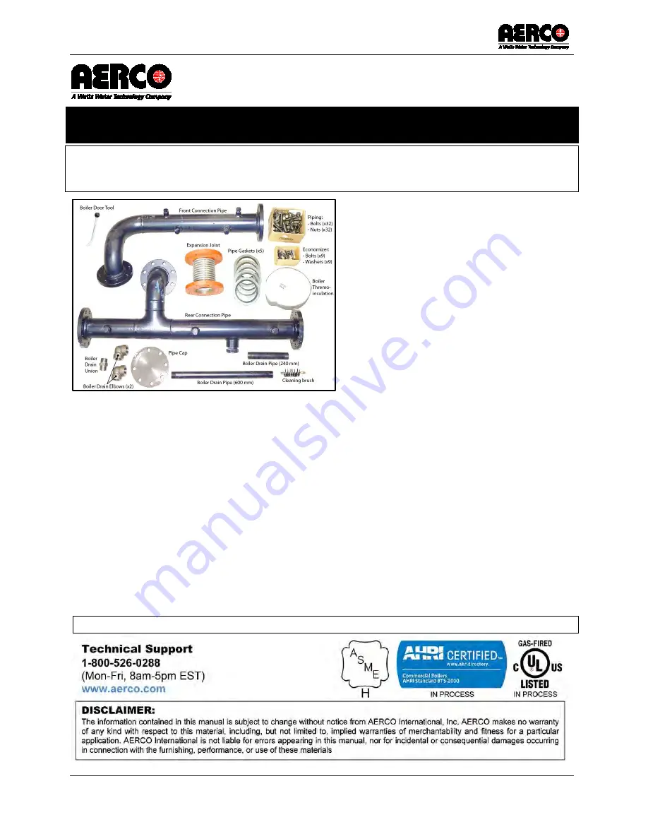
Page 8: ... PIPE 1 12 THERMOINSULATING MATERIAL KIT FOR BURNER HEAD 1 13 SCREW BETWEEN Stainless Steel 4th Pass AND BOILER 9 14 LARGE WASHERS BETWEEN Stainless Steel 4th Pass AND 9 15 CONN PIPE SUPPORT 2 16 BOLTS 4 17 NUTS for CONNECTION PIPE 4 18 LOCK WASHERS for CONNECTION PIPE 8 19 TUBE CLEANING BRUSH 1 20 DOOR OPENING TOOL 1 Figure 5 3 MFC Assembly Materials Supplied with Boiler Shown After Installation ...

Page 9: ...Quantity and Part Number vary depending upon pressure requirements Relief valve 2 Pipe Nipple 3 Bushing 4 1 123675 2 Tridicator 5 1 121700 Low Water Cut Off 6 1 24441 Condensate Trap 7 1 64115 Aquastat 8 1 64116 Manual Reset Aquastat 9 1 99235 Thermowell PRIMARY COLD WATER INLET SECONDARY COLD WATER INLET HOT WATER OUTLET OMM 0108_0A AERCO International Inc 100 Oritani Dr Blauvelt NY 10913 Page 9 ...

Page 10: ...re 6 1 Boiler Drain Assembly and Configuration MEASURE THIS DIMENSION ON THE STAINLESS STEEL 4th PASS BOILER DRAIN ASSEMBLY PARTS NOTE Assemble drain assembly as shown and attach to boiler at angle indicated BEFORE performing any other assembly tasks CONDENSATE DRAIN PIPING DRAIN PIPING FROM BOILER NOTCH FOR BOILER DRAIN BOILER WITH DRAIN PIPING INSTALLED AT ANGLE TO MATCH DIMENSION BELOW STAINLES...

Page 11: ...d on Stainless Steel 4th Pass Figure 6 3 Example of Condensate Drain Piping Installed to Condensate Trap 4th PASS CONDENSATE PORT 1 PIPING TO CONDENSATE TRAP CONDENSATE TRAP CONNECT TO 4 th PASS CONDENSATE PORT 1 TO NEUTRALIZER OR DRAIN CONDENSATE DRAIN PIPING 4 th PASS CONDENSATE PORT 2 CONNECT TO 4 th PASS CONDENSATE PORT 2 FLEX HOSE ELBOW UNION NIPPLE TEE NIPPLE NIPPLE UNION NIPPLE BOILER SIDE ...

Page 12: ...ess Steel 4th Pass frame as shown in Figure 7 1 Figure 7 1 Lifting the Stainless Steel 4th Pass by Straps at the Four Lifting Holes 2 Guide the Stainless Steel 4th Pass into the correct position in relation to the boiler see Figure 7 2 NOTE There is a hooked lower rim on the boiler that must fit onto the Stainless Steel 4th Pass inner lower inner rim lip see Figure 7 2 when mating the two together...

Page 13: ...Boiler Drain Piping 5 Lower the Stainless Steel 4th Pass and place into position ensuring it will position properly on the boiler housekeeping pad 6 Align the flange of the Stainless Steel 4th Pass inside the lip of the boiler as indicated in Figure 7 4 7 Use a wrench to adjust the supporting feet of the Stainless Steel 4th Pass on either side per Figure 4 11 to level and adjust the Stainless Stee...

Page 14: ...6 Tighten bolts incrementally in cross hatch pattern to ensure even tightness to a torque value of 10 to 20 ft lbs Figure 7 5 Stainless Steel 4th Pass Bolt Washer Locations and Attachment to Boiler Figure 7 6 Stainless Steel 4th Pass Bolt Washer Locations and Attachment to Boiler 4th PASS WASHER BOLT BOILER TAPPED HOLE IN BOILER Page 14 of 32 AERCO International Inc 100 Oritani Dr Blauvelt NY 1091...

Page 15: ...igure 8 2 Connection Rear Connection Pipe onto the Boiler 2 Retrieve a pipe gasket from the assembly kit and position it between the connection pipe flange and the boiler flange 3 Retrieve the eight bolts and nuts and install to secure the pipe flange to the boiler flange BUT DO NOT ENTIRELY TIGHTEN YET 4 Ensure that the pipe is level adjust the support bracket of the boiler to support the pipe an...

Page 16: ... 4 Secure to the boiler inlet flange with eight 8 bolts and nuts SECURE BUT DO NOT TIGHTEN Figure 8 4 Figure 8 4 Installing the Front Connection Pipe 5 Align front connection pipe with the expansion joint and attempt to secure the pipe flange to the joint flange with four 4 bolts and nuts into the four holes aligned with the secured holes on the other end of the flange 6 Insert a gasket between th...

Page 17: ...ection 8 3 for torque values required for the three sizes of 11 Bring the pipe support bracket up to the pipe and secure CAUTION Consistently tighten each nut alternately only a couple of turns to maintain even compression around all flanges and along piping assembly Refer to Section 8 3 for torque value according to pipe size Ensure that there is a pipe gasket between all piping connections 12 If...

Page 18: ...g table Pipe Connection Torque Values 4 Inch Pipe Connections 120 ft lbs 6 Inch Pipe Connections 210 ft lbs 8 Inch Pipe Connections 210 ft lbs Figure 8 7 MFC Piping Assembly Installed onto Boiler Stainless Steel 4th Pass GASKET GASKET REAR CONNECTION PIPE FRONT CONNECTION PIPE GASKET GASKET GASKET 8 x NUTS BOLTS 8 x NUTS BOLTS 8 x NUTS BOLTS 8 x NUTS BOLTS ENDCAP 8 x NUTS BOLTS EXPANSION JOINT Pag...

Page 19: ...ndary low water Cutoff Optional Manual Reset High Limit Operating High Limit Temperature Sensor for Modulating Control Tridicator Pressure Relief Valve s Figure 9 1 indicates the ports that will be used for installing the control and safety devices listed above Figure 9 1 Location of Ports Used for Installing Safety and Control Devices PRIMARY LWCO SECONDARY LWCO Optional MANUAL RESET HIGH LIMIT O...

Page 20: ...priate pipe dope to the threads 3 Install the LWCO sensor s by screwing it into the port as shown in Figure 9 2b 4 Retrieve the LWCO module 2 and install onto the LWCO sensor s by slipping the holes over the screws on the sensor mounting flange as shown in Figure 9 3 Tighten screws to secure in place Figure 9 2a Front Conn Pipe Ports for LWCO s Figure 9 2b LWCO Sensor Installed Figure 9 3 Installi...

Page 21: ...res 9 4 9 6 for suggested location of the Tridicator on the boiler hot water outlet pipe and install into appropriate port in the orientation shown 9 4 Temperature Sensor For Modulation Control Installation Installing the Temperature Sensor for Modulating Control 1 Retrieve the Temperature Sensor for Modulating Control and associated thermowell from the kit and apply an appropriate pipe dope to th...

Page 22: ...lded together Each must be individually run to a suitable discharge location Installing the Pressure Relief Valve s 1 Retrieve the Safety Relief Valve and associated bushing and pipe nipple from the kit and apply an appropriate pipe dope to the threads Any excess should be wiped off to avoid getting any joint compound into the valve body 2 Refer to Figure 9 6 for Safety Relief Valve location and i...

Page 23: ...low rate necessary for the boiler and that it is provided with all control and safety devices provided for by the regulations referred to above In particular when using gas o Check that the gas supply pipe complies with the regulations in force o Check that all the gas connections are sealed o Check that the boiler room vents are of sufficient size to ensure the air flow dictated by the regulation...

Page 24: ...ner onto the boiler opening slipping the four Blower Burner mounting flange holes over the four threaded studs around the boiler opening Figure 10 2a 4 Assemble the four nuts onto the four threaded studs and alternately tighten each bolt to ensure an even fit 5 Retrieve the white thermal insulation from the installation kit open the boiler door and insert the insulation around the flange of the bu...

Page 25: ...ctions Figure 10 3 Blower Burner Gas and Oil Connection Locations 10 3 Burner Blower Wiring Refer to Appendix A for a wiring diagram of the Riello burner used in the MFC Series boilers REVERSIBLE GAS INLET OIL CONNECTIONS OMM 0108_0A AERCO International Inc 100 Oritani Dr Blauvelt NY 10913 Page 25 of 32 GF 146 IN Ph 800 526 0288 12 15 2015 ...

Page 26: ...11 2 Reversing the Opening Direction of the Burner Door Since there are already integral hinges on both sides of the door the only procedures necessary to reverse the opening direction is to reverse the left and right side door fixing hardware and then to ensure a tight seal and proper opening of the door making adjustments if necessary Instructions for reversing the door direction follow WARNING ...

Page 27: ...uld be switched in a X pattern with one opening side and one hinge side nut always completely secured Start by reversing the upper left open side bolt with the lower right hinge side nut as shown in Figure 11 2 WARNING NEVER REMOVE ALL FOUR BARREL NUTS AT THE SAME TIME Figure 11 2 Switching Upper Left and Lower Right Bolts 3 Use the door opening tool to loosen upper left nut washer and remove Figu...

Page 28: ...11 5b open Side Nut to Lower Right 8 Perform the same procedure above only by reversing the lower left opening side nut with the upper right hinge side nut as illustrated in Figure 11 6 CAUTION When cross changing the barrel nuts always make sure that the other two barrel nuts are fastened so that they hold the door WARNING NEVER REMOVE ALL FOUR BARREL NUTS AT THE SAME TIME Figure 11 6 Switching U...

Page 29: ...rm the following Adjusting the Boiler Door Vertical Adjustment 1 Determine which hinges need adjustment 2 With the door ajar loosen the vertical adjustment locking nuts of the hinge 3 Adjust the vertical adjustment nut as required to raise or lower the hinge bolt 4 When satisfied with the adjustment retighten the locking nut Figure 11 8 Example Problem for Adjusting Vertical Adjustment Nut on Hing...

Page 30: ...4 Check the proper adjustment in depth ensuring that the door manually pushed up to the stop plate naturally returns to the slightly ajar position This is to ensure the hinge side door seal Figure 11 9 Adjusting Horizontal Adjustment Nut on Hinge For any problems related to the reversal and adjustment of the door we recommend contacting AERCO technical support team at 1 800 526 0288 PROBLEM Hinge ...

Page 31: ...ly For burners not supplied through AERCO consult the respective burner manufacturer for proper connection points and additional support Connect the safety and control devices supplied with the boiler to the burner control terminals shown below LWC Aquastats and temperature control sensor OMM 0108_0A AERCO International Inc 100 Oritani Dr Blauvelt NY 10913 Page 31 of 32 GF 146 IN Ph 800 526 0288 1...

Page 32: ... Log Date Description Changed By 12 15 2015 Rev A Initial Release Curtis Harvey International Inc AERCO International Inc 2015 Page 32 of 32 AERCO International Inc 100 Oritani Dr Blauvelt NY 10913 OMM 0108_0A 12 15 2015 Ph 800 526 0288 GF 146 IN ...

Reviews: