background image

NAV/COMM Test Set

Maintenance Manual

1002-5600-4P0

IFR 4000

Summary of Contents for IFR 4000

Page 1: ...NAV COMM Test Set Maintenance Manual 1002 5600 4P0 IFR 4000...

Page 2: ...reserved No part of this publication may be reproduced stored in a retrieval system or transmitted in any form or by any means electronic mechanical photocopying recording or otherwise without the pri...

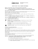
Page 3: ...MAINTENANCE MANUAL IFR 4000 FOR QUALIFIED SERVICE PERSONNEL ONLY...

Page 4: ...MAINTENANCE MANUAL IFR 4000 THIS PAGE INTENTIONALLY LEFT BLANK...

Page 5: ...NTENANCE MANUAL IFR 4000 Cable Statements For continued EMC compliance all external cables must be three meters or less in length For continued EMC compliance all external cables must be double shield...

Page 6: ...MAINTENANCE MANUAL IFR 4000 THIS PAGE INTENTIONALLY LEFT BLANK...

Page 7: ...ERMINAL Terminal that may supply or be supplied with AC or DC voltage DC TERMINAL Terminal that may supply or be supplied with DC voltage AC TERMINAL Terminal that may supply or be supplied with AC or...

Page 8: ...UITS WITH POWER ON PC BOARDS WHEN TAKEN OUT OF THE SET MUST BE LAID ON A GROUNDED CONDUCTIVE MAT OR STORED IN A CONDUCTIVE STORAGE BAG REMOVE ANY BUILT IN POWER SOURCE SUCH AS A BATTERY BEFORE LAYING...

Page 9: ...nts Introduction Chapter 2 Section 1 Servicing 2 1 Section 2 Troubleshooting 2 2 Section 3 Disassembly Reassembly 2 3 Section 4 Parts List 2 4 Appendix A Connector Pin Out Tables Appendix B Test Equip...

Page 10: ...MAINTENANCE MANUAL IFR 4000 TABLE OF CONTENTS Page 2 Aug 1 04 THIS PAGE INTENTIONALLY LEFT BLANK...

Page 11: ...al before attempting to perform maintenance on this equipment Only qualified personnel should perform maintenance on this equipment ORGANIZATION This manual is divided into the following Chapters and...

Page 12: ...MAINTENANCE MANUAL IFR 4000 INTRODUCTION Page 2 Aug 1 04 THIS PAGE INTENTIONALLY LEFT BLANK...

Page 13: ...2 ESD 2 2 3 2 3 EMC and Safety Compliance 2 2 3 2 3 Calibration Verification 2 2 3 1 A General 2 2 3 1 1 Calibration Verification Schedule 2 2 3 2 2 Controls Connectors and Indicators 2 2 3 2 3 Test...

Page 14: ...3 1 1 2 Disassembly Precautions 2 3 1 1 3 ESD 2 3 1 2 4 EMC and Safety Compliance 2 3 1 2 C Procedures 2 3 1 3 1 Battery 2 3 1 3 2 Fuse 2 3 1 5 3 Case Assy 2 3 1 7 4 Power Supply PCB Assy 2 3 1 9 5 R...

Page 15: ...ti Function PCB Assy Block Diagram 2 2 1 4 Processor PCB Assy Block Diagram 2 2 1 9 RF Assy Block Diagram 2 2 1 15 Troubleshooting Table 2 2 2 4 Power Meter Calibration Setup 2 2 3 58 Composite Assy 2...

Page 16: ...MAINTENANCE MANUAL IFR 4000 2 LIST OF ILLUSTRATIONS TABLES Page 2 Aug 1 04 THIS PAGE INTENTIONALLY LEFT BLANK...

Page 17: ...d with isopropyl alcohol 3 Remove dust and dirt from connectors with soft bristled brush 4 Cover connectors not in use with suitable dust cover to prevent tarnishing of connector contacts 5 Clean cabl...

Page 18: ...racked insulation and bad contacts 4 Inspect Circuit Boards for O Corrosion or damage to connectors O Damage to mounted components including crystals and ICs O Freedom from foreign material 5 Inspect...

Page 19: ...full current and run the Test Set at the same time as long as the input voltage is within range 1 Battery Charger The battery charger is a boost type converter This battery charger monitors the batter...

Page 20: ...power A low voltage cutoff is also incorporated into the ON OFF circuitry 4 Protection Circuitry The protection circuitry has four basic functions related to the DC input The battery has internal pro...

Page 21: ...C_IN 11 TO 32 Vdc CROWBAR CHARGE SUPERVISOR INPUT OUTPUT AND FUSE INPUT CONVERTER CONT PWM 10 Vdc 5 V CONVERTER 100 mA TYPICAL 16 V CONVERTER 25 mA TYPICAL CONT PWM 056M 01 16 Vdc 5 Vdc 1 A TYPICAL 1...

Page 22: ...E STATUS 3 3 V 5 V 16 V SER PROM PROCESSOR BUS I F BUS RS 232 SYSTEM PORT USB PERIPHERIAL PORT USB HOST PORT CNTRST BKLT KEYPAD I F LCD LCD BACKLIGHT PIEZO KEYPAD CHARGE POWER LEDS 3 3 V 3 3 V MKR MOD...

Page 23: ...within the FPGA The FPGA on the Multi Function PCB Assy supports several types of programming methods Slave Serial Master Serial Slave Parallel and Boundary Scan mode In Master Serial a local serial...

Page 24: ...ed with the new data This requires that the data be read prior to the next value getting written to the holding registers The counter data is read at address locations 40022004 and 40022006h The lower...

Page 25: ...wn MCLK signal AF2_CLK and serial bus Functionally AF Gen 2 is used for 150 Hz in LOC or G S 9960 for VOR and the second tone in SELCAL mode The separate clock and serial bus is for VOR mode with the...

Page 26: ...Hz Reference and the 30 Hz Variable signal that corresponds to a particular bearing setting The counter is programmable in 0 to 3600 that corresponds to a heading from 0 to 360 degrees in 0 1 degree...

Page 27: ...terrupt controller timers parallel and serial interfaces and on chip debug support The microprocessor contains 4 kB of cache and 8 kB of on chip SRAM The microprocessor runs at a maximum clock speed o...

Page 28: ...it device that provides the H W configuration user definable jumpers and the NVRAM battery status The FPGA on the Multi Function PCB Assy supports Slave Serial Master Serial Slave Parallel and Boundar...

Page 29: ...witch The AM modulator a PI configuration PIN diode attenuator provides the AM modulation and the fine increment output level adjustment and output leveling functions The level control inputs as seria...

Page 30: ...nal is routed to another RF switch and then through the straight through path of a directional coupler to the ANT Connector When the Test Set is set in Tri Mode operation a separate oscillator generat...

Page 31: ...an analog to digital converter that is used as a software controlled threshold The receive signal passes through the attenuators which can be used as part of a coarse AGC if needed The signal bypasses...

Page 32: ...MAINTENANCE MANUAL IFR 4000 2 2 1 Page 14 Aug 1 04 THIS PAGE INTENTIONALLY LEFT BLANK...

Page 33: ...RIDGE 31 dB SWR CONNECTOR 31 dB DDS 400 MHz DDS CONTROL 40 MHz OSC 4 10 MHz ATTEN CONTROL IF PLL CONTROL FM DEMOD OUT DEMOD 450 MHz FM LEVEL CONTROL MAIN AM MOD DAC 20 dB 75 MHz ANTENNA INPUT OVERLOAD...

Page 34: ...MAINTENANCE MANUAL IFR 4000 2 2 1 Page 16 Aug 1 04 THIS PAGE INTENTIONALLY LEFT BLANK...

Page 35: ...Cleaning connector and or switch contacts with alcohol repairs many types of digital and analog circuit malfunctions O The following inspection procedures are used to locate obvious malfunctions with...

Page 36: ...OLTAGES AND POWER INPUTS 2 ESD CAUTION THIS EQUIPMENT CONTAINS PARTS SENSITIVE TO DAMAGE BY ELECTROSTATIC DISCHARGE ESD CAUTION THE POWER SUPPLY ASSY MULTI FUNCTION PCB ASSY RF ASSY AND PROCESSOR PCB...

Page 37: ...Connector Failure 6 12 RF I O Connector Failure 6 13 ANTENNA Connector Failure 6 14 REMOTE Connector Failure 6 15 MODE Select Key Failure 6 16 POWER Key Failure 6 17 Multi Function Soft Keys Failure...

Page 38: ...dc 1 Vdc If incorrect probable source of failure is the External DC Power Supply 2 POWER Indicator does not light Probable sources of failure are the circuit between Power Supply PCB Assy and the LCD...

Page 39: ...is the Multi Function PCB Assy 7 Keypad fails Probable sources of failure are the Multi Function PCB Assy Keypad PCB Assy and the interconnecting cables 8 LCD fails Probable sources of failure are th...

Page 40: ...of failure is the RF Assy 14 REMOTE Connector Failure Probable sources of failure are the Multi Function PCB Assy and the interconnecting cables 15 MODE Select Key Failure Probable sources of failure...

Page 41: ...y Multi Function PCB Assy and the interconnecting cables 25 G S DDM DOWN Key Failure Probable sources of failure are the Keypad PCB Assy Multi Function PCB Assy and the interconnecting cables 26 LOC D...

Page 42: ...MAINTENANCE MANUAL IFR 4000 2 2 2 Page 8 Aug 1 04 THIS PAGE INTENTIONALLY LEFT BLANK...

Page 43: ...onnector 9 RF Level Accuracy RF I O Connector 12 RF Level Flatness RF I O Connector 14 Harmonic and Spurious 17 VSWR RF I O and SWR Connectors 19 Marker Beacon 21 VOR 22 Localizer 25 Glideslope 28 ILS...

Page 44: ...cord Verification Data Sheets are provided for recording the results obtained while performing the Verification Procedures NOTE It is recommended the technician reproduce copies of the Verification Da...

Page 45: ...y to display the Setup Menu 3 Press the H W TOOLS Soft Key to display the Hardware Tools Screen 4 Press the DIAGS Soft Key to display the Diagnostics Screen 5 Press the SELFTEST Soft Key to display th...

Page 46: ...E Select Key until the VOR Mode Screen 6 Set the Test Set as follows FIELD SETTING FREQ 108 000 MHz RF LVL 20 0 dBm MOD TONE OFF 7 Verify 108 0 MHz 1 ppm on the Modulation Analyzer 8 Press the MODE Se...

Page 47: ...Set as follows FIELD SETTING FREQ 225 000 MHz RF LVL 20 0 dBm MOD TONE OFF 25 If the UHF Mode Screen is in RECEIVING Mode press the SWITCH GEN RX Soft Key to switch the COMM UHF Mode Screen to GENERA...

Page 48: ...PROCEDURE 38 Set the FREQ Field to 118 003 MHz 39 Verify 118 003 MHz 1 ppm on the Modulation Analyzer 40 Set the FREQ Field to 118 004 MHz 41 Verify 118 004 MHz 1 ppm on the Modulation Analyzer 42 Dis...

Page 49: ...to display the Setup Menu 4 Set the PORT Field to ANT 5 Press the MODE Select Key until the VOR Mode Screen is displayed 6 Set the Test Set as follows FIELD SETTING FREQ 108 000 MHz RF LVL 30 0 dBm M...

Page 50: ...22 If the VHF AM Mode Screen is in RECEIVING Mode press the SWITCH GEN RX Soft Key to switch the COMM VHF AM Mode Screen to GENERATING Mode 23 Verify 30 dBm 3 dB on the Power Meter 24 Set the FREQ Fie...

Page 51: ...ess the MODE Select Key until the VOR Mode Screen is displayed 6 Set the Test Set as follows FIELD SETTING FREQ 108 000 MHz RF LVL 10 0 dBm MOD TONE OFF M MOD 0 7 Set the Power Meter to 108 000 MHz 8...

Page 52: ...EQ Field to 137 000 MHz 31 Set the Power Meter to 137 000 MHz 32 Set the RF LVL Field to 10 dBm 33 Record 10 dBm level on the Power Meter 34 Set the RF LVL Field to 10 dBm 35 Record 10 dBm level on th...

Page 53: ...57 Set the RF LVL Field to 10 dBm 58 Record 10 dBm level on the Power Meter 59 Set the RF LVL Field to 10 dBm 60 Record 10 dBm level on the Power Meter 61 Set the FREQ Field to 400 000 MHz 62 Set the...

Page 54: ...he PORT Field to RF I O 5 Press the MODE Select Key until the VOR Mode Screen is displayed 6 Set the Test Set as follows FIELD SETTING FREQ 108 000 MHz RF LVL 40 0 dBm MOD TONE OFF M MOD 0 7 Verify 40...

Page 55: ...TCH GEN RX Soft Key to switch the COMM VHF AM Mode Screen to GENERATING Mode 23 Verify 40 dBm 2 dB on the Power Meter 24 Set the FREQ Field to 118 000 MHz 25 Verify 40 dBm 2 dB on the Power Meter 26 D...

Page 56: ...5 Press the MODE Select Key until the VOR Mode Screen is displayed 6 Set the Test Set as follows FIELD SETTING FREQ 108 000 MHz RF LVL 20 0 dBm MOD TONE OFF M MOD 0 7 Set the Power Meter to 108 000 M...

Page 57: ...EQ Field to 137 000 MHz 31 Set the Power Meter to 137 000 MHz 32 Set the RF LVL Field to 20 dBm 33 Record 20 dBm level on the Power Meter 34 Set the RF LVL Field to 40 dBm 35 Record 40 dBm level on th...

Page 58: ...57 Set the RF LVL Field to 20 dBm 58 Record 20 dBm level on the Power Meter 59 Set the RF LVL Field to 40 dBm 60 Record 40 dBm level on the Power Meter 61 Set the FREQ Field to 400 000 MHz 62 Set the...

Page 59: ...FREQ 108 000 MHz RF LVL 0 0 dBm MOD TONE OFF M MOD 0 6 Verify the harmonic is 20 dBc and the spurious is 35 dBc 7 Press the MODE Select Key until the GLIDESLOPE Mode Screen is displayed 8 Set the Test...

Page 60: ...e spurious is 35 dBc 17 Press the MODE Select Key until the COMM UHF Mode Screen is displayed 18 Set the Test Set as follows FIELD SETTING FREQ 400 000 MHz RF LVL 0 0 dBm MOD TONE OFF M MOD 0 19 If th...

Page 61: ...RF I O CONNECTOR 2 Set the Spectrum Analyzer Tracking Generator Level to 0 dBm 3 Set the Spectrum Analyzer Tracking Generator Frequency to 75 225 and 400 MHz and record the levels as reference 4 Conn...

Page 62: ...G GENERATOR INPUT SWR 056M 21 10 Set the Spectrum Analyzer Tracking Generator Frequency to 75 225 and 400 MHz and record the levels 11 Calculate the return loss for the levels recorded in Steps 3 and...

Page 63: ...Menu 4 Set the PORT Field to ANT 5 Press the MODE Select Key until the MARKER BEACON Mode Screen is displayed 6 Set the Test Set as follows FIELD SETTING FREQ 75 000 MHz RF LVL 10 0 dBm MOD TONE 400...

Page 64: ...6 Set the Test Set as follows FIELD SETTING FREQ 108 000 MHz RF LVL 10 0 dBm MOD TONE 1020 Hz M MOD CAL 30 Hz MOD 0 9960 Hz MOD 0 7 Verify 1020 Hz 0 02 with 2 0 distortion and an AM Depth of 30 AM 2 A...

Page 65: ...z MOD 30 TO FROM TO 21 Set the BRG Field to the following settings and verify readings on the Modulation Analyzer BRG READING 30 210 0 1 90 270 0 1 150 330 0 1 210 30 0 1 270 90 0 1 330 150 0 1 22 Set...

Page 66: ...24 Aug 1 04 STEP PROCEDURE 27 Set the BRG Field to the following settings and verify readings on the Modulation Analyzer BRG READING 1 1 0 1 2 2 0 1 10 1 10 1 0 1 10 2 10 2 0 1 28 Disconnect the Modu...

Page 67: ...DE Select Key until the LOCALIZER Mode Screen is displayed 6 Set the Test Set as follows FIELD SETTING FREQ 108 100 MHz RF LVL 10 0 dBm MOD TONE 1020 Hz M MOD CAL DEV STEP FIXED LOC DDM 0 000 CENTER T...

Page 68: ...g 0 200 RIGHT 0 200 0 0015 DDM 3 of setting 15 Set the DEV STEP Field to VAR 16 Set the LOC DDM Field to the following settings and verify readings on the Modulation Analyzer LOC DDM READING 0 094 0 0...

Page 69: ...MAINTENANCE MANUAL IFR 4000 2 2 3 Page 27 Aug 1 04 STEP PROCEDURE 19 Set the 90 150 Hz Field to 0 20 Disconnect the Modulation Analyzer from the ANT Connector...

Page 70: ...layed 6 Set the Test Set as follows FIELD SETTING FREQ 334 700 MHz RF LVL 10 0 dBm M MOD CAL DEV STEP FIXED 90 150 Hz OFF TONE DEL 150 7 Verify 90 Hz 0 02 with 2 5 distortion and an AM Depth of 40 AM...

Page 71: ...48 DDM 3 of setting 0 178 0 178 0 0048 DDM 3 of setting 0 179 0 179 0 0048 DDM 3 of setting 14 Set the Test Set as follows FIELD SETTING DEV STEP FIXED G S DDM 0 000 CENTER PHASE ACCURACY 15 Set the 9...

Page 72: ...ELD SETTING FREQ 108 100 MHz RF LVL 30 0 dBm MOD TONE 400 Hz Marker ON M MOD CAL 7 Verify 75 MHz 1 ppm and tone frequency of 400 Hz 0 02 with 5 distortion and an AM Depth of 95 AM 5 AM on the Modulati...

Page 73: ...n the Modulation Analyzer LOC DDM READING 0 000 CENTER 0 000 0 0015 DDM 0 093 LEFT 0 093 0 0015 DDM 3 of setting 0 093 RIGHT 0 093 0 0015 DDM 3 of setting 0 155 LEFT 0 155 0 0015 DDM 3 of setting 0 15...

Page 74: ...5 Set the 90 150 Hz Field to 0 GLIDESLOPE 26 Disconnect the Modulation Analyzer and 10 dB Pad from the ANT Connector and connect the Measuring Receiver to the ANT Connector 27 Load Calibration Factors...

Page 75: ...zer to AM Measurement 3 Press the SETUP Key to display the Setup Menu 4 Set the PORT Field to ANT 5 Press the MODE Select Key until the COMM VHF AM Mode Screen is displayed 6 Set the Test Set as follo...

Page 76: ...yzer to AM Measurement 3 Press the SETUP Key to display the Setup Menu 4 Set the PORT Field to ANT 5 Press the MODE Select Key until the COMM VHF AM Mode Screen is displayed 6 Set the Test Set as foll...

Page 77: ...nerator to 35 dBm 7 Set the RF Signal Generator to the following settings and verify readings on the Test Set FREQUENCY READING 10 MHz 10 MHz 1 ppm 1 count 10 001 MHz 10 001 MHz 1 ppm 1 count 100 101...

Page 78: ...ollows FIELD SETTING FREQ 312 000 MHz RF LVL 10 0 dBm MOD TONE 1020 Hz M MOD CAL 19 Set Function Generator Frequency to 1 00001 MHz 20 Verify 1 00001 MHz 1 ppm 1 count on the Test Set 21 Set Function...

Page 79: ...dBm 50 Record as X5 10 dBm 90 Record as X6 5 dBm 10 Record as X7 5 dBm 50 Record as X8 5 dBm 90 Record as X9 4 Press the SETUP Key to display the Setup Menu 5 Set the PORT Field to ANT 6 Press the MO...

Page 80: ...gnal Generator from the ANT Connector and connect the RF Signal Generator Output to the RF I O Connector 13 Set the RF Generator Level and AM Depth as follows and verify the AM readings LEVEL AM DEPTH...

Page 81: ...NG Frequency 165 MHz Level 20 dBm 3 Set the RF Generator Tone and FM Deviation as follows and record the FM readings TONE FM DEVIATION FM READINGS 400 Hz 15 kHz Record as X1 400 Hz 10 kHz Record as X2...

Page 82: ...Hz 1 kHz X6 0 4 1 08 Reading X6 0 4 0 92 10 Press the SETUP Key to display the Setup Menu 11 Set the PORT Field to RF I O 12 Set the RF Signal Generator Level to 10 dBm 13 Disconnect the RF Signal Gen...

Page 83: ...the FREQ Field as follows and verify readings on the Test Set FREQ READINGS 75 1 000 0 2 20 of reading 137 1 000 0 2 20 of reading 225 1 000 0 2 20 of reading 312 1 000 0 2 20 of reading 400 1 000 0...

Page 84: ...ing 312 2 000 0 2 20 of reading 400 2 000 0 2 20 of reading 9 Disconnect the 100 Load from the SWR Connector and connect the 150 Load to the SWR Connector 10 Set the FREQ Field as follows and verify r...

Page 85: ...r Output and the RF Power Amplifier Output to the RF I O Connector 6 Set the RF Signal Generator Frequency and the RF Power Amplifier Level to the following settings and verify the readings on the Tes...

Page 86: ...y 118 0 MHz 1 ppm ________ 22 Verify 137 0 MHz 1 ppm ________ 26 Verify 225 0 MHz 1 ppm ________ 28 Verify 312 0 MHz 1 ppm ________ 30 Verify 400 0 MHz 1 ppm ________ 35 Verify 118 001 MHz 1 ppm _____...

Page 87: ...10 dBm level __________ 16 Record 10 dBm level ________ 20 Record 10 dBm level __________ 22 Record 10 dBm level ________ 27 Record 10 dBm level __________ 29 Record 10 dBm level ________ 33 Record 1...

Page 88: ...dBm 12 dBm 2 5 dB ________ 22 dBm 22 dBm 2 5 dB ________ 32 dBm 32 dBm 2 5 dB ________ 42 dBm 42 dBm 2 dB ________ 52 dBm 52 dBm 2 dB ________ 62 dBm 62 dBm 2 dB ________ 72 dBm 72 dBm 2 dB ________ 8...

Page 89: ...dBm level __________ 66 Record 40 dBm level ________ 67 Verify flatness difference between levels recorded in Steps 8 14 20 27 33 39 46 52 58 and 64 is 1 dB ________ 68 Verify flatness difference bet...

Page 90: ...z 1 3 ________ 225 MHz 1 3 ________ 400 MHz 1 35 ________ SWR CONNECTOR 10 Record levels 75 MHz ________ 225 MHz ________ 400 MHz ________ 11 Calculate return loss for Steps 3 and 10 and record ______...

Page 91: ...AM Depth of 30 AM 2 AM ________ 13 Verify AM Depth of 60 AM 4 AM ________ FM DEVIATION ACCURACY 15 Verify 480 Hz 25 Hz ________ BEARING ACCURACY 21 Verify readings 30 210 0 1 ________ 90 270 0 1 ____...

Page 92: ...3 0 0015 DDM 3 of setting ________ 0 093 RIGHT 0 093 0 0015 DDM 3 of setting ________ 0 155 LEFT 0 155 0 0015 DDM 3 of setting ________ 0 155 RIGHT 0 155 0 0015 DDM 3 of setting ________ 0 200 LEFT 0...

Page 93: ...0 091 DOWN 0 091 0 003 DDM 3 of setting ________ 0 175 UP 0 175 0 003 DDM 3 of setting ________ 0 175 DOWN 0 175 0 003 DDM 3 of setting ________ 0 400 UP 0 400 0 003 DDM 3 of setting ________ 0 400 DO...

Page 94: ...90 Hz 0 02 with 2 5 distortion and AM Depth of 20 AM 2 AM ________ 17 Verify 150 Hz 0 02 with 2 5 distortion and AM Depth of 20 AM 2 AM ________ 20 Verify readings 0 000 CENTER 0 000 0 0015 DDM 3 of...

Page 95: ...2 with 2 5 distortion and AM Depth of 30 AM 2 AM ________ 16 Frequency Counter 7 Verify readings 10 MHz 10 MHz 1 ppm 1 count ________ 10 001 MHz 10 001 MHz 1 ppm 1 count ________ 100 101 MHz 100 101 M...

Page 96: ...AM readings X1 1 1 Reading X1 0 9 ________ X2 1 1 Reading X2 0 9 ________ X3 1 1 Reading X3 0 9 ________ X4 1 1 Reading X4 0 9 ________ X5 1 1 Reading X5 0 9 ________ X6 1 1 Reading X6 0 9 ________ 13...

Page 97: ...0 4 1 08 Reading X6 0 4 0 92 ________ 19 SWR Meter 4 Verify readings 75 1 000 0 2 20 of reading ________ 137 1 000 0 2 20 of reading ________ 225 1 000 0 2 20 of reading ________ 312 1 000 0 2 20 of...

Page 98: ...____ 100 MHz 1 0 W 1 0 W 8 of reading 1 count ________ 100 MHz 5 0 W 5 0 W 8 of reading 1 count ________ 100 MHz 10 0 W 10 0 W 8 of reading 1 count ________ 100 MHz 20 0 W 20 0 W 8 of reading 1 count...

Page 99: ...nect the Measuring Receiver to the Signal Generator and calibrate the Measuring Receiver in Tuned RF Level Mode at the following frequencies storing the calibration in the storage location indicated 1...

Page 100: ...onal coupler Record as A z Measure the loss between the Signal Generator and the end of the coaxial cable going to the RF I O Connector Record as B z Subtract Loss B from Loss A and record Power Meter...

Page 101: ...m output and no modulation The Signal Generator should have a frequency error of 0 1 PPM 4 Press the START Soft Key to begin the TCXO CAL Sequence 5 When the TCXO CAL Sequence is complete press the SA...

Page 102: ...ALLOW THE POWER TERMINATION TO COOL 14 When the POWER METER CAL Sequence is complete press the SAVE RETURN Soft Key to return to the MISC CAL Screen FM DEV 15 Press the FM DEV Soft Key to display the...

Page 103: ...Sequence Turn modulation OFF to set and check RF level Toggling the UUT Modulation field between OFF and ON and the Measuring Receiver between AM and TUNED RF LEVEL several times may be required to me...

Page 104: ...uirements of the steps 12 When the LOC AMPL LEVEL Sequence is complete press the SAVE RETURN Soft Key to return to the AMPL LEVEL Cal Screen MKR 13 Press the MKR Soft Key to display the MKR AMPL LEVEL...

Page 105: ...must be 0 1 dB 6 Reference the following z Step 1 of VOR CAL Sequence Select 3 kHz Low Pass Filter on the Measuring Receiver z Step 2 of VOR CAL Sequence Select 15 kHz Low Pass Filter on the Measurin...

Page 106: ...Screen 18 Connect Measuring Receiver Sensor Head to the ANT Connector 19 Set Measuring Receiver input frequency to 110 05 MHz For AM measurements use the 3 kHz Low Pass Filter Use no High Pass filter...

Page 107: ...terconnect Diagram 4 56A1A1 Power Supply PCB Assy 5 56A1A2 Chassis Assy 12 56A1A2A1 Keypad PCB Assy 13 56A1A2A2 Processor PCB Assy 15 56A1A2A3 Multi Function PCB Assy 25 56A1A2A4 LCD Assy 37 56A1A3 RF...

Page 108: ...MAINTENANCE MANUAL IFR 4000 2 2 4 Page 2 Aug 1 04 THIS PAGE INTENTIONALLY LEFT BLANK...

Page 109: ...GNATORS WITH 56A1 A2W1J1 A2A4BKLT A3J3 A2A3J5 A2A3J9 A2A3J10 A2A3J12 A2A3J13 W2P2 18 14 15 A2 W3P1 W9P2 A2A4INTFC A3J4 W3P2 A2A3J8 2 5 17 8 16 7 J1 J2 J3 J4 13 BT1P1 A1J1 A1J2 W1J1 BT1 W9P1 1 4 W12P2...

Page 110: ...C AM MOD W4 W6 W7 W9 SWR VIDEO MKR DET W10 W12 W13 E14 RF I O E28 J1 J1 E3 J1 REMOTE J3 A1J3 AUX I O A1J4 ANTENNA A1J1 SWR J2 A1J2 RF I O A1A2A4 LCD 7110 5600 000 7010 5630 700 A1A2A1 KEYPAD 7010 5630...

Page 111: ...25 R24 U4 R22 R27 C43 R36 TP5 C47 Q11 R35 Q12 R34 L5 Q20 Q23 R50 R57 Q19 Q22 L1 U1 C9 Q3 C16 C8 C27 R8 TP1 R3 C7 R4 R5 C10 R6 C11 C17 C20 TP4 L3 Q6 Q7 C28 CR7 R23 Q8 C42 C46 R51 Q51 R56 R30 R33 Q13 R4...

Page 112: ...ug 1 04 056M 05b CAUTION CONTAINS PARTS AND ASSEMBLIES SUSCEPTIBLE TO DAMAGE BY ELECTROSTATIC DISCHARGE ESD PREFIX ALL REFERENCE DESIGNATORS WITH 56A1A1 1 J1 5 F1 BOTTOM VIEW Figure 7 Power Supply PCB...

Page 113: ...MAINTENANCE MANUAL IFR 4000 2 2 4 Page 7 Aug 1 04 Figure 7 Power Supply PCB Assy Sheet 3 of 7 0000 5630 500 C Circuit Schematic Sheet 1 of 5 56A1A1...

Page 114: ...MAINTENANCE MANUAL IFR 4000 2 2 4 Page 8 Aug 1 04 Figure 7 Power Supply PCB Assy Sheet 4 of 7 0000 5630 500 C Circuit Schematic Sheet 2 of 5 56A1A1...

Page 115: ...MAINTENANCE MANUAL IFR 4000 2 2 4 Page 9 Aug 1 04 Figure 7 Power Supply PCB Assy Sheet 5 of 7 0000 5630 500 C Circuit Schematic Sheet 3 of 5 56A1A1...

Page 116: ...MAINTENANCE MANUAL IFR 4000 2 2 4 Page 10 Aug 1 04 Figure 7 Power Supply PCB Assy Sheet 6 of 7 0000 5630 500 C Circuit Schematic Sheet 4 of 5 56A1A1...

Page 117: ...MAINTENANCE MANUAL IFR 4000 2 2 4 Page 11 Aug 1 04 Figure 7 Power Supply PCB Assy Sheet 7 of 7 0000 5630 500 C Circuit Schematic Sheet 5 of 5 56A1A1...

Page 118: ...TS AND ASSEMBLIES SUSCEPTIBLE TO DAMAGE BY ELECTROSTATIC DISCHARGE ESD 056M 012 2 3 11 8 A2A4BKLT A2A4INTFC 5 1 10 W1J1 14 16 9 A2A2 A2A4 A2JTB1 13 A2A3 A2A5 A2A1J1 A1A3J11 9 12 A2A1 PREFIX ALL REFERE...

Page 119: ...NS PARTS AND ASSEMBLIES SUSCEPTIBLE TO DAMAGE BY ELECTROSTATIC DISCHARGE ESD PREFIX ALL REFERENCE DESIGNATORS WITH 56A1A2A1 S1 S2 S3 S4 S5 S6 S7 S8 S9 S10 S14 S15 S12 S13 S20 S17 S11 S23 S21 S22 S18 S...

Page 120: ...MAINTENANCE MANUAL IFR 4000 2 2 4 Page 14 Aug 1 04 Figure 9 Keypad Assy Sheet 2 of 2 0000 5630 700 A Circuit Schematic 56A1A2A1...

Page 121: ...RN6 E2 33 J1 E14 W2 W1 C4 E12 W9 E13 W11 W10 U5 CR1 34 U4 E7 E6 E5 R4 R3 E9 C8 E10 C9 E8 E16 E15 RN12 E17 E18 C3 C1 1 U1 C2 TP1 E1 C5 U3 2 E4 R2 G1 RN9 C12 E11 RN8 RN14 RN37 RN36 RN35 RN34 U9 U13 E22...

Page 122: ...HARGE ESD PREFIX ALL REFERENCE DESIGNATORS WITH 56A1A2A2 BOTTOM VIEW C42 C41 E28 C40 C32 C30 C29 C24 C20 U6 C21 U7 RN13 RN10 W8 W7 W6 C17 C10 R6 C15 C13 C16 RN7 R5 C7 E3 RN1 RN3 RN4 C18 E3 C19 RN19 RN...

Page 123: ...MAINTENANCE MANUAL IFR 4000 2 2 4 Page 17 Aug 1 04 Figure 10 Processor PCB Assy Sheet 3 of 10 0000 5630 200 B Circuit Schematic Sheet 1 of 8 56A1A2A2...

Page 124: ...MAINTENANCE MANUAL IFR 4000 2 2 4 Page 18 Aug 1 04 Figure 10 Processor PCB Assy Sheet 4 of 10 0000 5630 200 B Circuit Schematic Sheet 2 of 8 56A1A2A2...

Page 125: ...MAINTENANCE MANUAL IFR 4000 2 2 4 Page 19 Aug 1 04 Figure 10 Processor PCB Assy Sheet 5 of 10 0000 5630 200 B Circuit Schematic Sheet 3 of 8 56A1A2A2...

Page 126: ...MAINTENANCE MANUAL IFR 4000 2 2 4 Page 20 Aug 1 04 Figure 10 Processor PCB Assy Sheet 6 of 10 0000 5630 200 B Circuit Schematic Sheet 4 of 8 56A1A2A2...

Page 127: ...MAINTENANCE MANUAL IFR 4000 2 2 4 Page 21 Aug 1 04 Figure 10 Processor PCB Assy Sheet 7 of 10 0000 5630 200 B Circuit Schematic Sheet 5 of 8 56A1A2A2...

Page 128: ...MAINTENANCE MANUAL IFR 4000 2 2 4 Page 22 Aug 1 04 Figure 10 Processor PCB Assy Sheet 8 of 10 0000 5630 200 B Circuit Schematic Sheet 6 of 8 56A1A2A2...

Page 129: ...MAINTENANCE MANUAL IFR 4000 2 2 4 Page 23 Aug 1 04 Figure 10 Processor PCB Assy Sheet 9 of 10 0000 5630 200 B Circuit Schematic Sheet 7 of 8 56A1A2A2...

Page 130: ...MAINTENANCE MANUAL IFR 4000 2 2 4 Page 24 Aug 1 04 Figure 10 Processor PCB Assy Sheet 10 of 10 0000 5630 200 B Circuit Schematic Sheet 8 of 8 56A1A2A2...

Page 131: ...68 RN16 E36 E34 E35 E37 E38 C91 C69 C76 U17 RN2 R31 TP7 RN9 Q7 E16 E18 E15 W16 C57 C54 Q8 C47 C46 E13 R67 E14 Q9 R50 R49 R52 R51 1 J11 2 Q4 Q1 R16 R15 R18 R17 Q5 Q2 R33 R32 R34 R35 C32 U8 RN7 TP10 E11...

Page 132: ...MAINTENANCE MANUAL IFR 4000 2 2 4 Page 26 Aug 1 04 Figure 11 Multi Function PCB Assy Sheet 2 of 12 0000 5630 300 C Circuit Schematic Sheet 1 of 11 56A1A2A3...

Page 133: ...MAINTENANCE MANUAL IFR 4000 2 2 4 Page 27 Aug 1 04 Figure 11 Multi Function PCB Assy Sheet 3 of 12 0000 5630 300 C Circuit Schematic Sheet 2 of 11 56A1A2A3...

Page 134: ...MAINTENANCE MANUAL IFR 4000 2 2 4 Page 28 Aug 1 04 Figure 11 Multi Function PCB Assy Sheet 4 of 12 0000 5630 300 C Circuit Schematic Sheet 3 of 11 56A1A2A3...

Page 135: ...MAINTENANCE MANUAL IFR 4000 2 2 4 Page 29 Aug 1 04 Figure 11 Multi Function PCB Assy Sheet 5 of 12 0000 5630 300 C Circuit Schematic Sheet 4 of 11 56A1A2A3...

Page 136: ...MAINTENANCE MANUAL IFR 4000 2 2 4 Page 30 Aug 1 04 Figure 11 Multi Function PCB Assy Sheet 6 of 12 0000 5630 300 C Circuit Schematic Sheet 5 of 11 56A1A2A3...

Page 137: ...MAINTENANCE MANUAL IFR 4000 2 2 4 Page 31 Aug 1 04 Figure 11 Multi Function PCB Assy Sheet 7 of 12 0000 5630 300 C Circuit Schematic Sheet 6 of 11 56A1A2A3...

Page 138: ...MAINTENANCE MANUAL IFR 4000 2 2 4 Page 32 Aug 1 04 Figure 11 Multi Function PCB Assy Sheet 8 of 12 0000 5630 300 C Circuit Schematic Sheet 7 of 11 56A1A2A3...

Page 139: ...MAINTENANCE MANUAL IFR 4000 2 2 4 Page 33 Aug 1 04 Figure 11 Multi Function PCB Assy Sheet 9 of 12 0000 5630 300 C Circuit Schematic Sheet 8 of 11 56A1A2A3...

Page 140: ...MAINTENANCE MANUAL IFR 4000 2 2 4 Page 34 Aug 1 04 Figure 11 Multi Function PCB Assy Sheet 10 of 12 0000 5630 300 C Circuit Schematic Sheet 9 of 11 56A1A2A3...

Page 141: ...MAINTENANCE MANUAL IFR 4000 2 2 4 Page 35 Aug 1 04 Figure 11 Multi Function PCB Assy Sheet 11 of 12 0000 5630 300 C Circuit Schematic Sheet 10 of 11 56A1A2A3...

Page 142: ...MAINTENANCE MANUAL IFR 4000 2 2 4 Page 36 Aug 1 04 Figure 11 Multi Function PCB Assy Sheet 12 of 12 0000 5630 300 C Circuit Schematic Sheet 11 of 11 56A1A2A3...

Page 143: ...MAINTENANCE MANUAL IFR 4000 2 2 4 Page 37 Aug 1 04 056M 09 Figure 12 LCD Assy 7110 5600 000 A 56A1A2A4...

Page 144: ...RTS AND ASSEMBLIES SUSCEPTIBLE TO DAMAGE BY ELECTROSTATIC DISCHARGE ESD 056M 014 PREFIX ALL REFERENCE DESIGNATORS WITH 56A1A3 A1J1 A1J2 A1J3 A1J4 A2J1 J1 J2 A1J5 A1J7 A1J6 1 2 19 20 1 2 33 34 AT1 A2 2...

Page 145: ...C45 C41 C32 R35 R36 C54 C74 C80 C72 C78 L8 R53 C56 C55 CR2 C66 C63 CR3 U13 C57 U15 C73 C77 C71 R58 C29 E20 R24 C23 U5 R25 R18 R17 R20 R19 R28 U4 C34 C30 R119 E16 C39 L3 R44 E10 J2 C123 E12 R86 C114 C...

Page 146: ...MAINTENANCE MANUAL IFR 4000 2 2 4 Page 40 Aug 1 04 Figure 13 RF Assy Sheet 3 of 16 RF Controller PCB Assy Sheet 2 of 6 56A1A3A1 0000 5630 400 F Circuit Schematic Sheet 1 of 5...

Page 147: ...MAINTENANCE MANUAL IFR 4000 2 2 4 Page 41 Aug 1 04 Figure 13 RF Assy Sheet 4 of 16 RF Controller PCB Assy Sheet 3 of 6 56A1A3A1 0000 5630 400 F Circuit Schematic Sheet 2 of 5...

Page 148: ...MAINTENANCE MANUAL IFR 4000 2 2 4 Page 42 Aug 1 04 Figure 13 RF Assy Sheet 5 of 16 RF Controller PCB Assy Sheet 4 of 6 56A1A3A1 0000 5630 400 F Circuit Schematic Sheet 3 of 5...

Page 149: ...MAINTENANCE MANUAL IFR 4000 2 2 4 Page 43 Aug 1 04 Figure 13 RF Assy Sheet 6 of 16 RF Controller PCB Assy Sheet 5 of 6 56A1A3A1 0000 5630 400 F Circuit Schematic Sheet 4 of 5...

Page 150: ...MAINTENANCE MANUAL IFR 4000 2 2 4 Page 44 Aug 1 04 Figure 13 RF Assy Sheet 7 of 16 RF Controller PCB Assy Sheet 6 of 6 56A1A3A1 0000 5630 400 F Circuit Schematic Sheet 5 of 5...

Page 151: ...R124 CR22 R131 C106 C116 R138 C111 R141 C110 R145 R147 E14 C41 R248 C51 L29 C232 C67 R78 U15 R125 R121 R137 R119 R128 C104 C96 R120 R130 R126 C99 R133 C105 R129 C101 R114 C97 R110 C91 R134 U21 R132 C...

Page 152: ...CR15 C38 E7 C37 R71 R74 C59 R72 R57 C43 R49 CR9 R45 R51 E6 R64 C58 C52 Q9 C56 R61 CR17 R77 R88 R82 C69 C68 C71 R87 U42 R98 L17 U25 R155 R152 C87 R117 C88 C98 R116 R115 U19 C94 C90 C126 R154 C124 W15 R...

Page 153: ...MAINTENANCE MANUAL IFR 4000 2 2 4 Page 47 Aug 1 04 Figure 13 RF Assy Sheet 10 of 16 RF Converter PCB Assy Sheet 3 of 9 56A1A3A2 0000 5630 600 G Circuit Schematic Sheet 1 of 6...

Page 154: ...MAINTENANCE MANUAL IFR 4000 2 2 4 Page 48 Aug 1 04 Figure 13 RF Assy Sheet 11 of 16 RF Converter PCB Assy Sheet 4 of 9 56A1A3A2 0000 5630 600 G Circuit Schematic Sheet 2 of 6...

Page 155: ...MAINTENANCE MANUAL IFR 4000 2 2 4 Page 49 Aug 1 04 Figure 13 RF Assy Sheet 12 of 16 RF Converter PCB Assy Sheet 5 of 9 56A1A3A2 0000 5630 600 G Circuit Schematic Sheet 3 of 6...

Page 156: ...MAINTENANCE MANUAL IFR 4000 2 2 4 Page 50 Aug 1 04 Figure 13 RF Assy Sheet 13 of 16 RF Converter PCB Assy Sheet 6 of 9 56A1A3A2 0000 5630 600 G Circuit Schematic Sheet 4 of 6...

Page 157: ...MAINTENANCE MANUAL IFR 4000 2 2 4 Page 51 Aug 1 04 Figure 13 RF Assy Sheet 14 of 16 RF Converter PCB Assy Sheet 7 of 9 56A1A3A2 0000 5630 600 G Circuit Schematic Sheet 5 of 6...

Page 158: ...MAINTENANCE MANUAL IFR 4000 2 2 4 Page 52 Aug 1 04 Figure 13 RF Assy Sheet 15 of 16 RF Converter PCB Assy Sheet 8 of 9 56A1A3A2 0000 5630 600 G Circuit Schematic Sheet 6 of 6...

Page 159: ...MAINTENANCE MANUAL IFR 4000 2 2 4 Page 53 Aug 1 04 Figure 13 RF Assy Sheet 16 of 16 RF Converter PCB Assy Sheet 9 of 9 7010 5630 900 A 0000 5630 600 G Buffer Amp PCB Assy 56A1A3A2A1...

Page 160: ...MAINTENANCE MANUAL IFR 4000 2 2 4 Page 54 Aug 1 04 THIS PAGE INTENTIONALLY LEFT BLANK...

Page 161: ...3 Keypad PCB Assy 15 LCD PCB Assy 16 B Preliminary Considerations 1 Tools Required TOOL SIZE DESCRIPTION SCREWDRIVER 2 PHILLIPS SCREWDRIVER 1 SLOTTED WRENCH 5 32 3 16 SOCKET PLIERS NEEDLE NOSE 2 Disas...

Page 162: ...CCEPTED ESD PRACTICES CAUTION THIS EQUIPMENT CONTAINS PARTS SENSITIVE TO DAMAGE BY ELECTROSTATIC DISCHARGE ESD 4 EMC and Safety Compliance All assemblies cables connectors plastic fasteners gaskets fi...

Page 163: ...LTAGES ARE PRESENT WITH CASE ASSY REMOVED IF POWER IS PRESENT STEP PROCEDURE 1 Remove external power sources and all external cables from the 4000 2 Loosen the four captive screws holding bumpers two...

Page 164: ...MAINTENANCE MANUAL IFR 4000 2 3 1 Page 4 Aug 1 04 STEP PROCEDURE 4 Disconnect the Battery wire harness 5 Remove the Battery...

Page 165: ...RE PRESENT WITH CASE ASSY REMOVED IF POWER IS PRESENT STEP PROCEDURE 1 Remove external power sources and all external cables from the 4000 2 Loosen the four captive screws holding bumpers two in back...

Page 166: ...MAINTENANCE MANUAL IFR 4000 2 3 1 Page 6 Aug 1 04 STEP PROCEDURE 4 Remove the Fuse...

Page 167: ...IFR 4000 2 3 1 Page 7 Aug 1 04 3 Case Assy PRELIMINARY PROCEDURES Battery para 2 3 1C 1 STEP PROCEDURE 1 Loosen the four captive screws holding bumpers two in back and two in front Remove bumpers 2 R...

Page 168: ...MAINTENANCE MANUAL IFR 4000 2 3 1 Page 8 Aug 1 04 STEP PROCEDURE 3 Remove four screws 4 Open the Case Assy...

Page 169: ...3 1 Page 9 Aug 1 04 4 Power Supply PCB Assy PRELIMINARY PROCEDURES Case Assy para 2 3 1C 3 STEP PROCEDURE 1 Disconnect wire cable and ribbon cable from the Power Supply PCB Assy 2 Remove eight screws...

Page 170: ...INTENANCE MANUAL IFR 4000 2 3 1 Page 10 Aug 1 04 5 RF Assy PRELIMINARY PROCEDURES Case Assy para 2 3 1C 3 STEP PROCEDURE 1 Disconnect ribbon cable from the RF Assy 2 Remove two semi rigid coaxial cabl...

Page 171: ...MAINTENANCE MANUAL IFR 4000 2 3 1 Page 11 Aug 1 04 STEP PROCEDURE 3 Disconnect six coaxial cables from the RF Assy 4 Remove 11 screws 5 Remove the RF Assy...

Page 172: ...0 2 3 1 Page 12 Aug 1 04 6 Processor PCB Assy PRELIMINARY PROCEDURES Case Assy para 2 3 1C 3 STEP PROCEDURE 1 Remove jumper from Multi Function PCB Assy 2 Remove four nuts and four lock washers 3 Remo...

Page 173: ...para 2 3 1C 3 Processor PCB Assy para 2 3 1C 6 STEP PROCEDURE 1 Disconnect three ribbon cables from the Multi Function PCB Assy 2 Disconnect ribbon cable wire cable and four coaxial cables from the Mu...

Page 174: ...MAINTENANCE MANUAL IFR 4000 2 3 1 Page 14 Aug 1 04 STEP PROCEDURE 3 Remove 11 screws 4 Remove Multi Function PCB Assy...

Page 175: ...Page 15 Aug 1 04 8 Keypad PCB Assy PRELIMINARY PROCEDURES Case Assy para 2 3 1C 3 Processor PCB Assy para 2 3 1C 6 Multi Function PCB Assy para 2 3 1C 7 STEP PROCEDURE 1 Remove 12 screws and five she...

Page 176: ...PRELIMINARY PROCEDURES Case Assy para 2 3 1C 3 STEP PROCEDURE 1 Disconnect wire cable and ribbon cable from Multi Function PCB Assy CAUTION EXERCISE CAUTION WHEN REMOVING THE RIBBON CABLE FROM THE MU...

Page 177: ...RS CAUTION REPLACE EACH REMOVED PLASTIC FASTENER IN SAME LOCATION AS MARKED AND CONFIGURED PRIOR TO REMOVAL CAUTION AVOID EXPOSING COMPONENTS TO EXCESSIVE HEAT WHEN SOLDERING 3 ESD CAUTION THIS EQUIPM...

Page 178: ...verse sequence of disassembly O Replace RF gasket if torn or damaged O Torque the 11 screws on the RF Assy to 8 in lbs O Torque the two semi rigid coaxial cable connectors to 10 in lbs 6 Processor PCB...

Page 179: ...CTION 4 PARTS LIST To order parts contact Aeroflex Customer Service Department 10200 West York Street Wichita KS 67215 8935 Telephone 800 835 2350 FAX 316 524 2623 Email service aeroflex com ASSEMBLY...

Page 180: ...P 4000 1002 5600 8P0 INSTRUCTIONS ANTENNA 4000 1002 5600 9P0 CARD PP PASSWORD IFR 4000 1201 0909 900 ANTENNA 1201 5601 000 ANTENNA 75MHZ 4000 1412 5653 000 CASE TRANSIT 4000 2289 0001 009 CAP TNC FEMA...

Page 181: ...ER BNC TNC 17 1414 5651 800 COVER REMOTE 18 2803 0125 005 SCREW 4 40 X 1 8 SHOULDER A1 7010 5630 500 PCB ASSY POWER SUPPLY A2 7005 5640 100 ASSY CHASSIS A3 7005 5640 400 ASSY RF BT1 7020 0012 500 ASSY...

Page 182: ...M 12 2801 0375 006 SCREW 2 56 X 3 8 PPHM 13 2818 0000 017 STANDOFF 188 HEX M F 187LG 14 2850 0000 012 NUT HEX SMALL PAT 2 56 16 2840 0000 004 WASHER LOCK INT TOOTH 2 A1 7010 5630 700 PCB ASSY KEYPAD A...

Page 183: ...TYPE INPUT OUTPUT SWR TNC RF OUTPUT AUX I O BNC N A INPUT OUTPUT DC POWER 2 5 mm CIRCULAR 2 5 mm center 5 5 mm outer diameter center positive 11 to 32 Vdc INPUT RF I O TNC RF 30 W CW MAX INPUT OUTPUT...

Page 184: ...USB Host 4 D_D D Data To From Upstream USB Host 5 TX RS 232 Data Output 6 RX RS 232 Data Input 7 CTS RS 232 Clear To Send Input 8 RTS RS 232 Request To Send Output 9 GND_DN1 Ground for Downstream USB...

Page 185: ...r Equivalent Audio Analyzer HP 8903A or Equivalent Signal Generator HP8657B or Equivalent Digital Multimeter HP 34401A or Equivalent Function Generator HP 33120A or Equivalent Spectrum Analyzer AN 920...

Page 186: ...MAINTENANCE MANUAL IFR 4000 APPENDIX B Page 2 Aug 1 04 THIS PAGE INTENTIONALLY LEFT BLANK...

Page 187: ...et 5280 ft sec miles hr 0 6818 miles km 1 609 ft sec 2 cm sec 2 30 48 miles meters 1609 ft sec 2 m sec 2 0 3048 miles nmi 0 8684 grams ounces 0 03527 miles hr ft sec 1 467 inches cm 2 54 miles hr km h...

Page 188: ...MAINTENANCE MANUAL IFR 4000 APPENDIX C Page 2 Aug 1 04 THIS PAGE INTENTIONALLY LEFT BLANK...

Page 189: ...11 95 MHz in 50 kHz steps LOC Preset 108 10 108 15 or 110 15 MHz LOC Variable 107 00 to 113 00 MHz in 50 kHz steps G S Channel 329 15 to 335 00 MHz in 50 kHz steps G S Preset 334 25 334 55 or 334 70 M...

Page 190: ...B Tri Mode Marker 13 dBm Fixed Accuracy 2 dB Tri Mode LOC 7 dBm Fixed Accuracy 2 dB Tri Mode G S 7 to 83 dBm in 0 5 dB steps Accuracy 3 dB RF I O Connector Single Carrier 12 to 130 dBm in 0 5 dB steps...

Page 191: ...30 AM Each Tone 1020 Hz Morse Code 10 AM Accuracy 2 Modulation Variable Range 0 to 55 AM 30 9960 and 1020 Hz Tones Distortion 2 5 in CAL Position FM Modulation 30 Hz Reference at 480 Hz Peak Deviation...

Page 192: ...50 Hz Tones 0 to 42 AM 1020 Hz Tone Distortion 2 5 in CAL Position LOC DDM Fixed Range 0 0 093 0 155 or 0 200 DDM and Tone Delete Accuracy 0 0015 DDM 1 5 A 3 of setting 10 dBm Output Level Variable Ra...

Page 193: ...2 Modulation Variable Range 0 to 50 AM 90 and 150 Hz Tones Distortion 2 5 in CAL Position G S DDM Fixed Range 0 0 091 0 175 or 0 400 DDM and Tone Delete Accuracy 0 003 DDM 2 5 A 3 of setting 10 dBm Ou...

Page 194: ...tion CAL Setting 95 AM Accuracy 5 Modulation Variable Single Carrier Only Range 0 to 95 AM Distortion Single Carrier 2 5 in CAL Position 67 to 10 dBm Tri Mode 5 in CAL Position COMM Mode COMM VHF AM a...

Page 195: ...vides amplitude modulation with SELCAL SELective CALling tones SELCAL Tone Frequency Accuracy 0 02 Transmit Modes Single Single Transmission Continuous 7 5 sec interval typical Modulation CAL Per SELC...

Page 196: ...as Time Base 1 Count Sensitivity ANT Connector 35 dBm RF I O Connector 10 dBm AUX I O Connector 1 Vp p Power Meter RF I O Connector Frequency Range 118 0 to 400 0 MHz Power Range 0 1 to 1 W 1 to 100 W...

Page 197: ...acy 10 of reading Sensitivity ANT Connector 20 dBm RF I O Connector 5 dBm FM Meter Audio Range 50 to 3000 Hz Deviation Range 1 to 15 kHz Accuracy 0 4 kHz 8 of reading Minimum input Level ANT Connector...

Page 198: ...pe Output Impedance 50 Typical Maximum Reverse Power 25 dBm VSW R 75 to 300 MHz 1 3 1 300 to 400 MHz 1 35 1 AUX Connector Type Input Output Impedance 800 Typical Maximum Input Level 5 Vp p Maximum 3 V...

Page 199: ...e 2 Altitude 4800 meters Operating Temperature 20 to 55 C Battery Charging temperature range is 5 to 40 C controlled by internal charger Storage Temperature 30 to 70 C Li Ion Battery must be removed w...

Page 200: ...MAINTENANCE MANUAL IFR 4000 APPENDIX D Page 12 Aug 1 04 THIS PAGE INTENTIONALLY LEFT BLANK...

Page 201: ...E CONTROLS CONNECTORS AND INDICATORS MODE RF LVL FREQ TONE M MOD SETUP LOC G S DDM uA CTRS BKLT DISPLAY CHARGE POWER ANT RF I O AUX I O SWR TE REMOTE RE 1 2 3 4 5 7 11 19 20 21 22 26 27 25 24 23 18 1...

Page 202: ...ONTRAST Key 24 DECREMENT SELECT Data Key 25 SELECT DATA UNIT MSB Key 26 SELECT DATA UNIT LSB Key 27 INCREMENT SELECT Data Key ALPHABETICAL LOCATION LIST 5 ANT Connector 2 AUX I O Connector 19 BACKLIGH...

Page 203: ...tains RS 232 USB Host and USB Peripheral connections 7 Display LCD 38 characters by 16 lines for main screen display with Soft Key boxes at the bottom of the screen 8 Multi Function Soft Keys Five Sof...

Page 204: ...etting 16 LOC DDM LEFT Key This Key slews the displayed Localizer DDM to the Left Increments are either FIXED or VAR Variable depending on the DDM DEV STEP Field setting 17 G S DDM DOWN Key This Key s...

Page 205: ...data in slewable fields such as FREQ This Key also selects data in fields that have fixed functions such as MOD TONE and MODE 25 SELECT DATA UNIT MSB Key This Key moves the slew cursor toward the MSB...

Page 206: ...MAINTENANCE MANUAL IFR 4000 APPENDIX E Page 6 Aug 1 04 THIS PAGE INTENTIONALLY LEFT BLANK...

Page 207: ...Bc Decibels below Carrier dBm Decibels above one Milliwatt DC Direct Current DDM Difference in Depth of Modulation DDS Direct Digital Synthesis deg Degrees DEL Delete DEV Deviation DIAGS Diagnostics D...

Page 208: ...Frequency RMS Root Mean Square ROM Read Only Memory RTS Request To Send R W Read Write RX Receive S Sec Seconds SELCAL Selective Calling SP Spacing SPM Scans per Minute SPR Synchronous Phase Reversal...

Page 209: ...3 1 p 16 Multi Function PCB Assy 2 3 1 p 13 Power Supply PCB Assy 2 3 1 p 9 Processor PCB Assy 2 3 1 p 12 RF Assy 2 3 1 p 10 Keypad PCB Assy 2 2 4 p 13 Circuit Schematic 2 2 4 p 14 LCD Assy 2 2 4 p 3...

Page 210: ...ency Counter 2 2 3 p 35 Glideslope 2 2 3 p 28 Harmonic and Spurious 2 2 3 p 17 ILS 2 2 3 p 30 Localizer 2 2 3 p 25 Marker Beacon 2 2 3 p 21 Power Meter 2 2 3 p 43 RF Accuracy 2 2 3 p 4 RF Level Accura...

Page 211: ...ility none of which shall form part of any contract We reserve the right to make design changes without notice CHINA Tel 86 10 6467 2716 Fax 86 10 6467 2821 FRANCE Tel 33 1 60 79 96 00 Fax 33 1 60 017...

Reviews: