background image


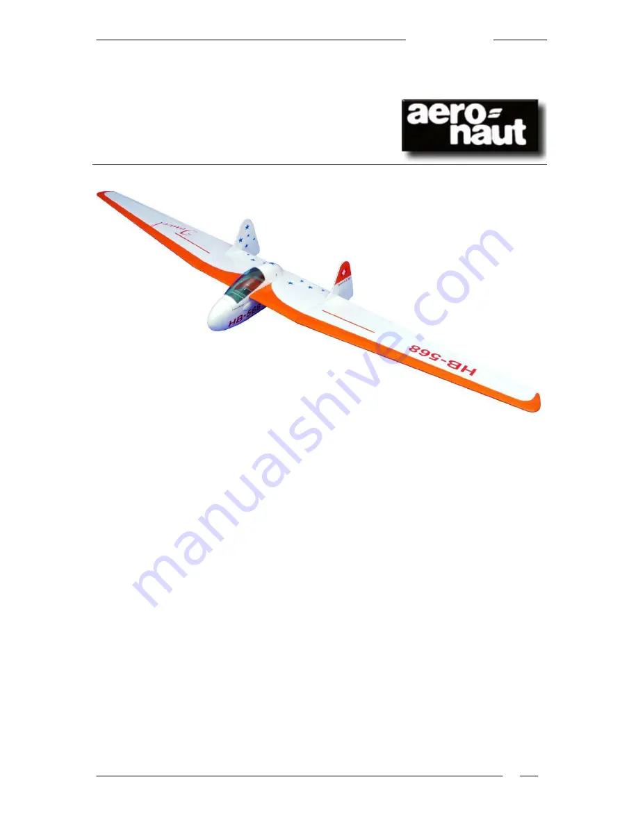
                                                                                                                       Fauvel AV-361


Fauvel AV-361 building instructions 


Building Instructions 
 
Fauvel AV-361 RC glider 
 

Order No. 1363/00


Specification:


Wingspan: 

approx. 3195 mm 

Length: 

approx. 800 mm 

Wing area: 

approx. 98 sq dm 

Weight, glider: 

2700 - 3500 g 

Wing loading: 

27.5 - 36 g / sq dm 

Weight, electric glider: 

3250 - 3800 g 

Wing loading: 

34 - 39 g / sq dm 

RC functions: 

Aileron 


Elevator 


Rudder 


Airbrake 


Aero-tow release (optional) 


Throttle (electric version) 

 
Recommended power system: 

“Actro 24-3”, 5 - 6S LiPo, 12 x 6.5” propeller 


“Actro 24-4”, 6S LiPo, 14 x 8” propeller 

 
Recommended RC components: 

Four high-quality standard servos 


Four wing-mounting servos, max. thickness 13 mm 


Receiver, min. six channels 


Receiver battery, min. 1200 mAh 

 
The full-size 

“Fauvel AV 36” was developed in France in 1951 as a single-seat sailplane, and gained 

an  excellent  reputation  even  then  for  its  outstanding  flying  qualities  and  unprecedented  level  of  in-
herent stability. Distance flights of 500 kilometres were not uncommon

. The “AV-361” presented here 

in model form was introduced in  1960 as a further development of the 

“AV-36”; the main differences 

were its greater wingspan and improved airfoil. 

Summary of Contents for Fauvel AV-361 RC glider

Page 1: ...LiPo 12 x 6 5 propeller Actro 24 4 6S LiPo 14 x 8 propeller Recommended RC components Four high quality standard servos Four wing mounting servos max thickness 13 mm Receiver min six channels Receiver battery min 1200 mAh The full size Fauvel AV 36 was developed in France in 1951 as a single seat sailplane and gained an excellent reputation even then for its outstanding flying qualities and unprec...

Page 2: ...ced fellow modeller for advice We assume that the builder of the model is conversant with the safe handling of standard modelling materials and adhesives soldering equipment and tools Certain areas of the model are necessarily left up to the modeller and are not described in detail in these instructions The wing Remove the three factory assembled uncovered wing panels from their protective sleeves...

Page 3: ...ng at a point exactly 123 mm from the leading edge and 10 mm away from the facing rib drill centre The fins Use white glue to join the top and bottom parts of the fins at the interlocking joints Ensure that they are not assembled the wrong way round the front and rear edges should line up flush It is best to lay the fin components flat on a film covered building board for this procedure weight the...

Page 4: ...lywood locating tongues from material in your scrap box and install them at the front of the canopy Every modeller will have his favourite method of locating canopies so you have free rein here Final work The receiver and receiver battery should be installed in the extreme fuselage nose A good method is to glue small plywood plates in place to which the components are attached using cable ties or ...

Page 5: ... cause interference to any other radio control systems in the vicinity typically through a channel clash two transmitters on the same frequency If possible join a model flying club where you will find plenty of friendly people to help with all your queries and problems Please note if damage ensues due to failure to observe these instructions the guarantee is rendered invalid We accept no liability...

Reviews: