background image


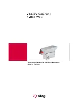
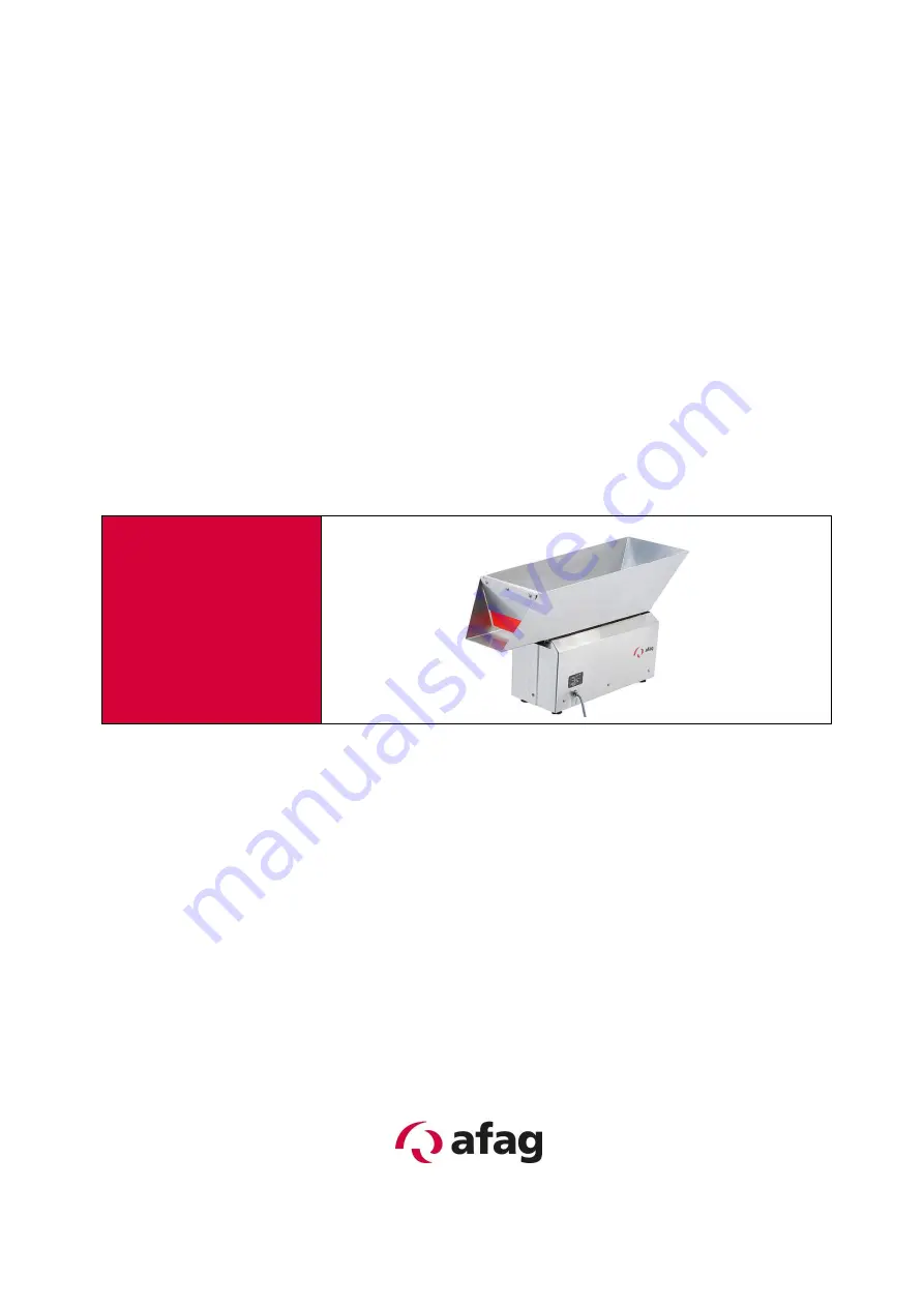
Vibratory hopper unit 

NVD 3 / NVD 4 


Translation of operating and installation instructions


Copyright by Afag GmbH


Summary of Contents for NVD 3 Series

Page 1: ...Vibratory hopper unit NVD 3 NVD 4 Translation of operating and installation instructions Copyright by Afag GmbH ...

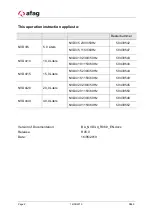
Page 2: ...Liters NVD4 10 230V 50Hz 50439543 NVD4 10 115V 60Hz 50439548 NVD4 15 15 0 Liters NVD4 15 230V 50Hz 50439544 NVD4 15 115V 60Hz 50439549 NVD4 20 20 0 Liters NVD4 20 230V 50Hz 50439545 NVD4 20 115V 60Hz 50439550 NVD4 40 40 0 Liters NVD4 40 230V 50Hz 50439546 NVD4 40 115V 60Hz 50439552 Version of Documentation BA_NVD3 4_R06 0_EN docx Release R06 0 Date 16 05 2019 ...

Page 3: ...ling the unit 10 3 3 Power supply 11 4 Operating instructions 12 4 1 Standard operation 12 4 2 Adjustments and settings of the NVD 12 4 3 Setting the distance between the vibrating plate and the support base 13 4 4 Torques 14 5 Maintenance instructions 15 5 1 Troubleshooting 15 5 2 Cleaning 17 5 3 Replacing springs or spring packages 18 5 4 Replacing the magnetic coil 19 5 5 Setting the air gap be...

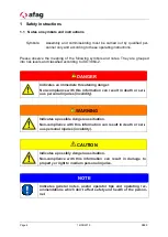
Page 4: ...an immediate threatening danger Non compliance with this information can result in death or seri ous personal injuries invalidity WARNING Indicates a possible dangerous situation Non compliance with this information can result in death or seri ous personal injuries invalidity CAUTION Indicates a possibly dangerous situation Non compliance with this information can result in damage to property or l...

Page 5: ...e vibratory hopper is intended to store component parts of different sizes forms and types of material The workpieces must meet the following requirements in order to ensure a problem free feeding they must be free of oil grease and burrs they must not be sticky they must not be statically charged they must not be magnetic no self magnetism they must be free of dirt and not be mixed with foreign p...

Page 6: ...e DGUV regulation 15 The definitions of Section 12 Indirect Effects Medical Implants remain unaffected by the above The alternating magnetic fields that occur in the immediate vicinity of certain vibration convey ors may affect the proper functions of active implants i e pacemakers and defibrillators Any one with active medical implants for which no individual risk assessment has been provided mus...

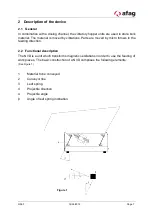
Page 7: ...ts are moved by micro throws in the feeding direction 2 2 Functional description The NVD is a unit which transforms magnetic oscillations in order to use the feeding of work pieces The basic construction of a NVD comprises the following elements See Figure 1 1 Material to be conveyed 2 Conveyor line 3 Leaf spring 4 Projectile direction α Projectile angle β Angle of leaf spring inclination Figure 1...

Page 8: ... angle of inclination of the leaf springs and carries out small throwing movements in a vertical direction to the leaf spring level On a cycle of the 50Hz alternating current supply the magnet achieves twice it s max imum pulling force while this is independent of the direction of current flow The mag net thereby produces an oscillating frequency of 100Hz This 100Hz oscillation is nec essary to ac...

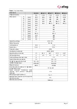
Page 9: ...istance 140 11 4 Device fuse F0 3 F0 1 Protection class IP54 Oscillations full wave 3000 3600 Weight without channel 15 38 3 39 7 41 5 46 7 Filling weight max 2 20 20 20 20 Spring package thickness max 8 10 Spring thickness standard 1 5 0 5 1 5 Air gap magnet anchor bolt 0 4 0 9 0 5 1 5 Installed magnet type EL60 20 EL96 33 Magnetic power 46 23 184 92 Environmental conditions for operation Tempera...

Page 10: ...ort means CAUTION During transport the NVD must only be held by the base The feeding channel is not to be held 3 2 Installing the unit For operation the NVD must always be mounted on a sufficiently proportioned foun dation There are 4 threaded holes located on the bottom side of the drive which are used to connect with the subframe see chapter 2 3 Technical Data When installing the NVD it must be ...

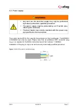
Page 11: ...eder may only be operated with the power sup ply specified on the name plate The control device IRG1 S is used for the activation of the bowl feeder The MSG801 or MSG802 can also be used Please note that an additional CEE connector plug Figure 3 is required for the MSG control devices Order number 11006982 Installation of the plug is only to be carried out by technically qualified personnel Figure...

Page 12: ... and condition the conveying capacity the quantity filled the foundation Surrounding are there other oscillating components with a disturbing influence Procedure for adjustment of the oscillating system WARNING Unplug the power cable before proceeding with further actions 1 check control unit settings see separate control unit s operating instructions 2 Remove the casing and check that all springs...

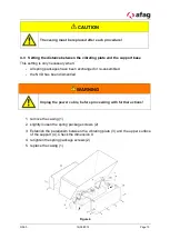
Page 13: ...g packages have been exchanged or re assembled the NVD has been dismantled WARNING Unplug the power cable before proceeding with further actions 1 remove the casing 1 2 slightly loosen the spring package screws 2 3 Establish the parallelism between the vibrating plate 3 and the upper surface of the support 4 Check the dimension X 4 retighten the spring package screws 2 5 replace the casing 1 Figur...

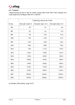
Page 14: ...w Strength class 8 8 Strength class 10 9 Strength class 12 9 M4 2 8 4 1 4 8 M5 5 5 8 1 9 5 M6 9 5 14 0 16 5 M7 15 5 23 0 27 0 M8 23 0 34 0 40 0 M10 46 0 68 0 79 0 M12 79 0 117 0 135 0 M14 125 0 185 0 215 0 M16 195 0 280 0 330 0 M18 280 0 390 0 460 0 M20 390 0 560 0 650 0 M22 530 0 750 0 880 0 M24 670 0 960 0 1120 0 M27 1000 0 1400 0 1650 0 M30 1350 0 1900 0 2250 0 by Dubbel 18th edition page G175 ...

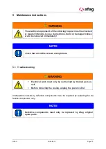
Page 15: ... be removed immediately NOTE check that all visible screws are tightness 5 1 Troubleshooting WARNING Electrical work must only be carried out by trained person nel Before removing the casing unplug the power cable Interruptions caused by defective components must be repaired by replacing the de fective component only NOTE Defective components must only be replaced by Afag original spare parts ...

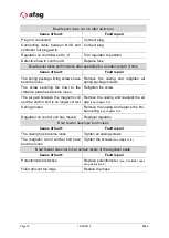
Page 16: ...he vibration plate has become loose Retighten the screw The air gap between the magnetic coil and the anchor bolt is no longer correct Remove the casing and readjust the air gap see chapter 5 5 Spring broken Remove the casing and replace the bro ken spring see chapter 5 3 Regulator on control unit has moved Readjust regulator Bowl feeder develops loud noises Cause of fault Fault repair The casing ...

Page 17: ...de tergent into bowl Don t placed bowl into a clean ing bath PET Macrolon plexi glass Vacuum cleaner and anti static spray Vacuum then spray with antistatic spray and rub off CAUTION If other cleaning agents or cleaning methods than those men tioned above are used the components can get permanently damaged so that the proper function of the vibrating hopper is no longer guaranteed WARNING The foll...

Page 18: ...rews 2 from the spring package 3 to be replaced 3 Reassemble the spring package The relevant spring cross section for the NVD can be taken from Chapter 2 3 NOTE If a spring was broken the number and thickness of the springs must correspond to the old package NOTE Opposite opposed spring packages must contain the same springs 4 mount the spring package and tighten the screws 2 5 check the air gap b...

Page 19: ...6 0 16 05 2019 Page 19 Figure 5 5 4 Replacing the magnetic coil see Figure 6 This procedure is only necessary when the magnetic coil is defective WARNING Before removing the casing unplug the power cable ...

Page 20: ... the Euro plug 2 from the control unit and disassemble 3 loosen the cable clamp 3 and pull the cable through 4 remove the screws 4 and exchange the magnet 5 5 reassemble in the reverse order NOTE This procedure generally includes adjustment of the air gap be tween the magnetic coil and the anchor bolt see chapter 5 5 Figure 6 ...

Page 21: ...ts 2 and 3 turn the hex nut in the desired direction to adjust the gap be tween the magnetic coil and the anchor bolt Retighten the hex nuts 2 and 3 3 use a feeler gauge 4 to set the air gap between the magnetic coil 5 and the anchor bolt 6 to between NVD 3 0 5 1 mm NVD 4 0 8 1 5 mm NOTE Set the anchor bolt so that there is a parallel air gap between the magnetic coil and the anchor bolt 4 mount t...

Page 22: ...umber NVD 3 NVD 4 Leaf spring 1 5 mm thickness 11006760 11006761 Table 3 Spare parts Type Designation Order number NVD 3 NVD 4 230V 50Hz 115V 60HZ 230V 50Hz 115V 60HZ Magnet WEH021 500141 50425628 WEH021 501141 50436143 WSN007 500119 50425626 WSN007 500219 50436144 Rubber buffer M5 11006834 M6 11006838 ...

Page 23: ... IRG and MSG types can be mounted in various different ways and offer extra controls for photoelectric barriers initiator elements or extern 24VDC sig nal For a detailed description of the controllers refer full range catalogue from AFAG GmbH Third party controllers can also be used as long as they meet the technical require ments Table 4 Controllers for NVDs Type Power supply Order number Comment...

Page 24: ...0 Sales sales afag com www afag com Switzerland Afag Automation AG Zuführtechnik Fiechtenstrasse32 CH 4950 Huttwil Tel 41 0 62 959 86 86 Fax 41 0 62 959 87 87 7 Waste disposal NVDs that are no longer in use should not be disposed of as complete units but dis mantled into separate materials and recycled Non recyclable components must be disposed of correctly ...

Reviews: