background image

1

INSTALLATION INSTRUCTIONS

IDEAA

®

 Mini Interior Distribution Cabinet 

TABLE OF CONTENTS

GENERAL .........................................................................................................................................2

SPECIFICATIONS .............................................................................................................................2

PACKAGE CONTENTS .....................................................................................................................2

PACKAGE CONTENTS: ACCESSORIES .........................................................................................3

REQUIRED TOOLS ..........................................................................................................................3

ADD-ON COMPONENTS ..................................................................................................................3

CABINET MOUNTING—WALL MOUNT ...........................................................................................3

LOCK AND UNLOCK EXTERIOR DOORS .......................................................................................4

CABLE PREPARATION ....................................................................................................................4

CABLE INSTALLATION  ....................................................................................................................5

COMPRESSION FITTING INSTALLATION ......................................................................................6

DISASSEMBLE COMPRESSION FITTING—CABLE REPLACEMENT ...........................................6

SPLICING ..........................................................................................................................................6

IDEAA SPLITTER MODULE INSTALLATION—MOUNT IDEAA SPLITTER MODULE ....................8

IDEAA SPLITTER MODULE INSTALLATION—ACTIVATE IDEAA SPLITTER MODULE ................9

MDU DROP CABLE INSTALLATION  .............................................................................................10

IDEAA SPLITTER MODULE INSTALLATION—CONNECT DISTRIBUTION FIBER ......................13

PASS THROUGH CONNECTION ...................................................................................................14

Summary of Contents for IDEAA Mini Interior Distribution Cabinet

Page 1: ...3 LOCK AND UNLOCK EXTERIOR DOORS 4 CABLE PREPARATION 4 CABLE INSTALLATION 5 COMPRESSION FITTING INSTALLATION 6 DISASSEMBLE COMPRESSION FITTING CABLE REPLACEMENT 6 SPLICING 6 IDEAA SPLITTER MODULE INST...

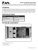
Page 2: ...two 1x32 IDEAA Splitter Modules The Mini IDC utilizes innovative jumper routing and drop strain relief to enable efficient fiber management Thanks to the adapter interface of the IDEAA splitter modul...

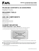
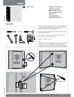
Page 3: ...UNTING 1 Using local engineering practices determine the mounting position of the cabinet on the wall 2 Mark the two upper mounting points to be pre drilled for cabinet placement Figure 1 Mounting Pos...

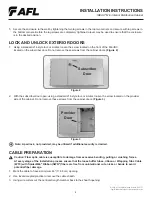
Page 4: ...r Wrapping Tube Cable WTC with SpiderWeb Ribbon SWR fibers are free from unintentional cuts nicks or bends to avoid potential fiber damage 1 Mark the cable to have a minimum 46 116 8 cm opening 2 Use...

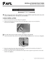
Page 5: ...tom of the Mini IDC 3 Install the compression fitting reference the Compression Fitting Installation section of this document Figure 5 4 Using local engineering practices determine which fibers will b...

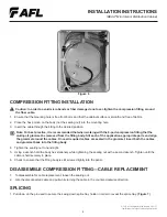
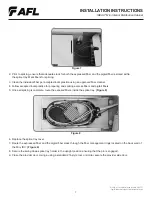
Page 6: ...t the multi port grommet be removed from the fitting body Slit each of the application appropriate ports and align the grommet around the cables Once all required cables are seated in the grommet inse...

Page 7: ...ed fiber cleaner 4 Follow accepted local practice for preparing and splicing express fibers and pigtail fibers 5 Once all splicing is complete route the exposed fibers inside the splice tray Figure 8...

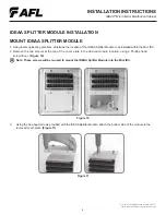
Page 8: ...A Splitter Module to be installed within the Mini IDC 2 Remove the two screws at the top of the cover plate in the desired module location using a Phillips head screwdriver Figure 10 Note These screws...

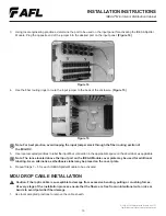
Page 9: ...s not active until it has been connected to the Input Field Caution When working with fiber optics do not look directly into the end of the fiber cable or adapter port A power meter may be used to det...

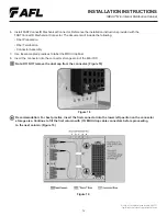
Page 10: ...he fiber routing section of the Mini IDC 5 Use local accepted practices to label the input fiber connection in the appropriate space on the door label as applicable Note The lance located above the in...

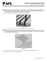
Page 11: ...collecting within the cabinet 2 Insert the 4 8 mm jacket into the MDU drop retention bracket Figure 16 Figure 16 3 Slide the 4 8 mm drop cable to the backmost position within the drop retention bracke...

Page 12: ...include the following Fiber Preparation Fiber Termination Connector Assembly 7 Use local accepted practices to label the MDU drop fiber 8 Insert the connector into the connector storage area of the Mi...

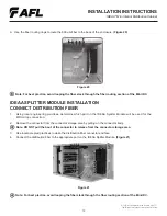
Page 13: ...e connector to release from the connector storage area 3 Use local accepted practices to clean the distribution fiber connector end face 4 Connect the distribution fiber to the appropriate port on the...

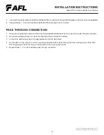
Page 14: ...e 3 Connect the distribution fiber to the appropriate port on the input field 4 Use the fiber routing rings to route the remaining distribution fiber slack through the fiber routing section of the Min...

Reviews: