background image

Agilent Technologies

Agilent Intuvo 9000 


Gas Chromatograph

Installation and First Startup

Summary of Contents for Intuvo 9000

Page 1: ...Agilent Technologies Agilent Intuvo 9000 Gas Chromatograph Installation and First Startup...

Page 2: ...not limited to the implied warranties of merchantability and fitness for a particular purpose Agilent shall not be liable for errors or for incidental or consequential damages in connection with the f...

Page 3: ...install the ALS tray support brackets 19 Intuvo 9000 7693A Tray Support Assembly kit contents 19 Install the pivot block and stop bracket 19 Connect the power cord and LAN cable 26 Turn on the GC 27 V...

Page 4: ...ENT cables 61 GC MS Agilent data system ALS 62 Additional cabling configurations 62 Install ALS if available 63 Install tray bracket onto the tray 7693A only 63 Install the tray on the GC 7693A only 6...

Page 5: ...le in a setup GC MSD Data System Headspace Sampler 104 GC External Events unspecified non Agilent instrument 104 Cable Diagrams 106 Analog signal cable general use G1530 60560 106 Agilent analog signa...

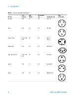
Page 6: ...6 Agilent Intuvo 9000 GC Installation...

Page 7: ...ation procedures for the Agilent Intuvo 9000 GC Some of the steps in this procedure are optional based on your installed components such as plumbing cryogenic cooling or valve actuator air Instruction...

Page 8: ...d for a successful installation Refer to the Agilent Intuvo 9000 GC GC MS and ALS Site Preparation Guide 2 If Agilent is delivering installation and familiarization services users of the instrument sh...

Page 9: ...4 inch od Fittings Tubing cutter Filters for gas supplies 7 16 inch and 9 16 inch open end wrenches for assembling Swagelok fittings Carrier and other gas supplies Pressure regulator for each gas sup...

Page 10: ...kits will arrive with the GC Most parts needed for installation will be found in the 9000 GC System Ship Kit Ship kits for the ordered inlet and detector will include the inlet and detector specific...

Page 11: ...gure 2 Back of the Intuvo 9000 GC Touch screen display Cooling intakes Front door handle Inlet Detector Split vent Septum purge vent Power on and status indicators Cooling intake Power receptacle Exha...

Page 12: ...or shows signs of stress notify both the carrier and your local Agilent sales office Keep all shipping materials for inspection by the carrier 2 Check the items received against the packing lists If t...

Page 13: ...st include sufficient space behind the GC to allow for cooling 1 Remove the GC from its shipping box Lift using the handle on the back panel and the flat area beneath the GC front Avoid lifting by the...

Page 14: ...The oven exhaust deflector accepts a 7 62 cm 3 in diameter exhaust duct and adds about 7 6 cm to the depth of the GC but this additional depth does not increase the depth required for proper ventilat...

Page 15: ...m with a computer monitor printer and hub requires five outlets The GC does not require a dedicated ground but since the GC can draw up to 12 A maximum depending on the line voltage you may not want o...

Page 16: ...oltage Amp Rating Cable length m Termination type Plug Termination Australia 240 10 2 5 AS 3112 China 220 10 4 5 GB 1002 Europe Korea 220 230 240 10 2 5 CEE 7 7 Type F Switzerland 220 16 2 5 SEC Type...

Page 17: ...ia 240 10 2 5 BS89 13 United States 120 15 2 5 NEMA 5 15P Europe 220 230 240 10 2 5 CEE 7 7 Type F Denmark Greenland 220 10 2 5 SR 107 2 D1 DK2 5A Argentina 220 10 Type I Chile 220 10 CEI 23 16 Type L...

Page 18: ...perly grounded receptacle is one that is connected to a suitable earth ground Proper receptacle grounding should be verified Make sure the GC is connected to a dedicated receptacle outlet Brazil 230 1...

Page 19: ...t bracket support bracket and support truss now Refer to the Intuvo 9000 7693A Tray Support Assembly accessory G7390A Intuvo 9000 7693A Tray Support Assembly kit contents Install the pivot block and s...

Page 20: ...20 Agilent Intuvo 9000 GC Installation 1 Installing the GC Install pivot block 1 Remove the GC top cover 2 Remove the GC right side panel 3 Remove left side panel...

Page 21: ...ew 0515 3005 5 Install the two pivot block backers G4580 00272 with two screws 0515 2113 then attach three screws 0515 2113 to the bottom three holes of the pivot block 6 If not using a D2 or MSD remo...

Page 22: ...stall the MSD frame cover 7 If using a D2 or MSD install the left side panel onto the GC Do not install the MSD frame cover 8 If not using a D2 or MSD install the MSD cover insert then attach the supp...

Page 23: ...Installing the GC 1 Agilent Intuvo 9000 GC Installation 23 a Match the slots on the left side of the GC b Secure the support truss with two thumbscrews 0515 6137...

Page 24: ...tallation 1 Installing the GC Install the stop bracket on the right side of the GC 1 Install the stop bracket with four screws 0515 2113 The label ONE DEGREE TILT should face outward 2 Install the rig...

Page 25: ...Installing the GC 1 Agilent Intuvo 9000 GC Installation 25 3 Reinstall the GC covers...

Page 26: ...26 Agilent Intuvo 9000 GC Installation 1 Installing the GC Connect the power cord and LAN cable LAN...

Page 27: ...Installing the GC 1 Agilent Intuvo 9000 GC Installation 27 Turn on the GC...

Page 28: ...es the GC touch screen and how to navigate through it to make settings and perform tasks on the GC Use the navigation arrows to view each screen Touch Cancel when done To skip displaying the Feature T...

Page 29: ...Installing the GC 1 Agilent Intuvo 9000 GC Installation 29...

Page 30: ...npacking Setting the system date time and IP address Setting the gas units gas types and similar choices Connecting gases and checking for leaks Installing a sampler if available Running a checkout sa...

Page 31: ...he GC clock The Current Time is based on a 24 hour clock The time set here is important for the time and date stamps used when collecting data and recording log entries such as maintenance tasks and e...

Page 32: ...stallation 1 Installing the GC Configure the GC IP address Touch Settings System Settings Network Enter the GC Host Name or IP address Gateway and Net Mask subnet mask For an isolated LAN installation...

Page 33: ...OR Table 3 Typical IP addresses for an isolated LAN GC Computer IP address 10 1 1 101 10 1 1 100 Subnet mask 255 255 255 0 255 255 255 0 Table 4 Cabling requirements 9000 GC connected to Required Cabl...

Page 34: ...ver 3395B 3396C Integrator Remote 9 pin 15 pin Analog 2 m 6 pin 03396 61010 G1530 60570 Non Agilent Integrator General purpose analog signal cable 2 m 6 pin G1530 60560 Non Agilent data system General...

Page 35: ...type If connected to an MS such as 5977A or 7000C D use the GC touch screen to identify the connected MS s IP address and to select the part information for example source type and pump type Touch Set...

Page 36: ...detector gas fittings Remove any cap from the cryogenic coolant fitting if present Remove any protective cap from the detector exhaust port or exhaust tubing On the top of the GC remove any tape used...

Page 37: ...move the screws that secure the MSD frame cover and remove the cover b Slide the detector tail brace out of the side of the GC c Reinstall the MSD frame cover If installing a 7693A tray assembly you c...

Page 38: ...g the GC and extension G4581 20522 can be found in the 9000 GC System Ship kit G3950 68000 5 Remove protective packaging 6 Open the oven door Loosen any ties that secure the oven packing in place and...

Page 39: ...t Intuvo 9000 GC Installation 39 7 Install the bus door G4581 60207 The door rests on two hinge pins in the GC 8 If you are not installing a tray MSD or D2 install the MSD cover insert assembly Oven p...

Page 40: ...your GC detector includes other settings for example a Lit Offset value for a flame ionization detector FID accept the default value for installation and checkout Touch Settings Configuration Inlet to...

Page 41: ...mplete installation instructions by browsing to the GC in a web browser This connection requires only that the device and the GC connect to the same LAN No Internet connection is required A direct con...

Page 42: ...pe Be careful to keep the tape away from the end of the fitting Two to three tightly wound wraps are sufficient Never use a liquid thread sealant Liquid thread sealants introduce contamination into th...

Page 43: ...nstallation 43 3 Install the regulator onto the compressed gas cylinder main fitting Check the thread type Some regulators use left hand thread fittings For left handed threads the nut will have a gro...

Page 44: ...ve pressurizing the primary side of the regulator c Turn OFF the tank main valve d Slowly turn the regulator knob clockwise to release bleed off the gas pressure e Close the regulator knob The image b...

Page 45: ...ll need 2 Cut the tubing to length with a tubing cutter Figure 5 Figure 5 Typical tubing cutter 3 Connect the tubing to the gas source with a Swagelok fitting See Appendix A Making Swagelok Connection...

Page 46: ...e Figure 6 shows the recommended trap order for the carrier gas and the recommended locations for On Off valves See also the Site Preparation Guide Figure 6 Plumbing the gas supplies 2 Cut the tubing...

Page 47: ...or a few minutes before connecting them to the GC flow modules If sharing carrier gas between an inlet and a detector we recommend using a Tee fitting that includes shutoff valves for performing leak...

Page 48: ...allation 1 Installing the GC When two detectors use the same gases we recommend using a Tee fitting Shutoff valves are not required TCD connections The carrier gas and reference gas must come from the...

Page 49: ...the connections Retest the connections continue tightening until all connections are leak free Set source gas pressures The pressure set at a tank regulator depends on these factors The inlet pressure...

Page 50: ...ressure must not exceed the lowest maximum operating pressure in the supply system Table 6 suggests starting values of source pressure Table 6 Suggested starting pressures Gas Use Source pressure Carr...

Page 51: ...he ECD exhaust vents through a coiled tube Connect tubing from the tube fitting at the end of this tubing to an exhaust hood via a hole in the back panel For a TCD you must supply vent tubing and fitt...

Page 52: ...52 Agilent Intuvo 9000 GC Installation 1 Installing the GC Detector cover Vent chimney Screw O Ring...

Page 53: ...fittings Connecting liquid carbon dioxide Materials needed 1 8 inch heavy wall stainless steel tubing WARNING Do not use copper or thin wall stainless steel tubing Either presents an explosion hazard...

Page 54: ...connect the supply tubing to the cryogenic valve inlet Connecting liquid nitrogen QOHW FU R FRROLQJ WWLQJ WARNING Liquid nitrogen is a hazard because of the extremely low temperatures and high pressur...

Page 55: ...the liquid N2 tank outlet with the fitting recommended by the supplier 4 Use a Swagelok fitting to connect the supply tubing to the cryogenic valve inlet WARNING If liquid nitrogen is trapped between...

Page 56: ...ntaminants could clog the inlet s cryo valve and expansion orifice or impact the proper operation of the GC Set the air supply pressure to 138 to 276 kPa 20 and 40 psig While air supplied from tanks c...

Page 57: ...coolant on the back of the GC Prepare enough tubing to reach from the supply to this outlet 2 Connect the supply tubing to the air supply outlet with the fitting recommended by the supplier 3 Use a S...

Page 58: ...contaminants Valve actuator air is supplied through 1 4 inch plastic tubing If your GC was ordered with valves the plastic tubing will already be attached to the actuators and will extend from the bac...

Page 59: ...cables label the cables as needed to identify their intended use and appropriate connector on the GC See Labeling BCD and EVENT cables Back panel connectors The figure below shows the connectors on t...

Page 60: ...connector This connector provides two passive contact closures and two 24 volt outputs for controlling external devices BCD input connector This connector provides two control relays and a BCD input...

Page 61: ...ge the GC logic board To prevent accidental damage the following BCD and Event cables come with labels that identify their intended use G1580 60710 External valve cable G1580 60730 Pulser Module Power...

Page 62: ...ons For additional cabling configurations see Appendix B Cabling Diagrams and Remote Start Stop LAN switch or hub 1 LAN cable 8121 0940 GC Computer 5977B MSD 2 APG Remote Cable G1530 60930 1 LAN cable...

Page 63: ...stall ALS if available If installing an ALS install it now Install tray bracket onto the tray 7693A only If a tray is not available skip this section 1 Gently park the gantry If new remove all of the...

Page 64: ...4 Agilent Intuvo 9000 GC Installation 1 Installing the GC 2 Place the bracket on the tray Tighten the captive screws Figure 8 Assembling the tray bracket to the tray Figure 9 Bracket and tray assemble...

Page 65: ...nstallation 65 Install the tray on the GC 7693A only If a tray is not available skip this section 1 Place tray on the GC inserting the tray bracket into the stop bracket 2 Lock the tray in place 3 Con...

Page 66: ...66 Agilent Intuvo 9000 GC Installation 1 Installing the GC Install the injector To install an injector 1 Install mounting post 2 Mount the injector 3 Connect the cable to the GC ALS 1 connector...

Page 67: ...gilent Intuvo 9000 GC Installation 67 Configure the ALS 1 Configure the injector and tray if installed Select the syringe size and wash mode as applicable The syringe supplied by Agilent with an injec...

Page 68: ...68 Agilent Intuvo 9000 GC Installation 1 Installing the GC Calibrate the tray if installed If installed calibrate the tray before first use...

Page 69: ...r checkout 1 Prepare a 2 mL screw top sample vial 2 Prepare 4 mL waste vials and place them into the turret 3 Prepare fresh solvent solutions as needed for the checkout sample for your detector type P...

Page 70: ...ion and test For an MS configuration with no other GC detector you will need to replace the simple D1 chip with the MS chip before installing the column Refer to the Intuvo 9000 GC Maintaining Your GC...

Page 71: ...s 1 Open the GC front door 2 Remove the bus door 3 Open the oven door 4 Remove the column plug and gasket a Remove the compression bolts using the torque driver b Remove the plug and discard c Remove...

Page 72: ...ing screw at the inlet base See Figure 2 b Gently depress the Guard chip heater assembly c Remove the plug from the inlet base and discard Figure 12 Remove the inlet base plug Remove plug Multimode in...

Page 73: ...Install the inlet chip a Remove the inlet cover b Slide open the Guard chip cover to expose the Guard chip compression bolt c Using the Intuvo torque driver loosen the Guard chip compression bolt unt...

Page 74: ...ip Slide the bottom connector of the inlet chip behind the Smart ID connector wire for the detector chip and insert the bottom connector into the column fitting on the bus Then insert the top connecto...

Page 75: ...bus h Figure 14 Click and run fittings i Rotate the clips to hold the inlet chip in place Figure 15 Place the inlet chip check your work j Insert the inlet chip Smart ID key into the lower socket to t...

Page 76: ...wer the Guard chip heater c Place the Guard chip left end into the inlet base For an MMI Guard chip avoid touching the upright tube against the sides of the opening d Rotate the body of the Guard chip...

Page 77: ...be obscured by the heater block If not reseat it f Finger tighten the Guard chip compression bolt until you feel slight contact on the Guard chip g Gently raise the Guard chip heater h Finger tighten...

Page 78: ...t the round gasket lobes into the slot of the click and run fitting then align the lobes into the inner pockets of the click and run fitting Note that the gasket is double sided 3 Locate the hole in t...

Page 79: ...llation 79 4 Check that the gasket s round lobes remain flat with no wrinkles and are centered on top of the mating flow chip sealing surfaces See the figure below Gasket lobes enter through slots in...

Page 80: ...so the click and run connectors mate into the right side bus fitting Grasp the column ring as shown in the figure and insert the column click and run connectors into the bus fitting The column connec...

Page 81: ...C 1 Agilent Intuvo 9000 GC Installation 81 c Check column placement The center hub of the column connector heater should fit in the slot in the column neck as shown below d Install the compression bol...

Page 82: ...flow chips If the compression bolts protrude from the bus fitting by more than about 1 thread the column may not be properly seated Remove the bolts and repeat step 2 4 Check column placement and tig...

Page 83: ...the column s Intuvo Smart ID Key into the lower USB connection along the right side of the oven e Close the oven door f Install the bus door 7 Install the bus door Place the torque wrench back in the...

Page 84: ...84 Agilent Intuvo 9000 GC Installation 1 Installing the GC 8 Close the GC front door...

Page 85: ...olumn Touch Method select Active method then touch Edit to access current GC temperatures and flows Set the column temperature to 20 C higher than the highest checkout method temperature do not exceed...

Page 86: ...top sample vial 1 The checkout sample is contained in sealed glass vials Wrap a piece of cloth or a paper towel around the vial to protect your fingers and snap the top off 2 Use a pipette to transfer...

Page 87: ...ckout method Find the complete checkout methods and procedures in the Operation Manual Enter the parameters for the checkout procedure If using an Agilent data system use it to create a checkout metho...

Page 88: ...he GC Run one injection When the GC becomes Ready Not ready light turns off make the injection and start the run For an ALS injection press on the GC or start the run from the data system as appropria...

Page 89: ...Installing the GC 1 Agilent Intuvo 9000 GC Installation 89 Evaluate Results Compare the chromatogram you generated with the one in the checkout procedure There should be a close resemblance...

Page 90: ...ngth filter for FPD Change to any alternate gas sources as needed for the new analysis Install the desired column and condition it per the manufacturer s recommendations Configure the GC to match any...

Page 91: ...ecommends that you check for any updates and install them if available GC firmware 1 Install the GC Firmware Update Tool a Place the Agilent GC and GC MS User Manuals Tools DVD into your PC s DVD driv...

Page 92: ...the GC download it If no firmware or help updates are available skip to the next section 4 Verify that if a new firmware version is available it is compatible with the current hardware and software F...

Page 93: ...First Startup Agilent Technologies A Making Swagelok Connections Making Swagelok Connections 94 Using a Swagelok Tee 97 The gas supply tubing is attached with Swagelok fittings If you are not familiar...

Page 94: ...inch nuts wrenches Procedure 1 Place a Swagelok nut back ferrule and front ferrule to the tubing as shown in Figure 17 Figure 17 Swagelok nuts and ferrules 2 Clamp a stainless steel plug or similar f...

Page 95: ...front ferrule is touching the plug Slide the Swagelok nut over the ferrule and thread it onto the plug 5 Push the tube fully into the plug then withdraw it approximately 1 to 2 mm see Figure 19 Figur...

Page 96: ...ure 21 Final tightening 9 Remove the plug from the fitting To connect the tubing with nut and ferrules to another fitting finger tighten the nut then use a wrench to tighten it 3 4 1 8 inch fittings o...

Page 97: ...1 8 inch Swagelok nuts and front and back ferrules 1 8 inch Swagelok Tee Two 7 16 inch wrenches 1 8 inch Swagelok cap optional Procedure 1 Cut the tubing where you want to install the Tee Connect the...

Page 98: ...98 Agilent Intuvo 9000 GC Installation A Making Swagelok Connections 2 Measure the distance from the Tee to the instrument fittings Attach copper tubing to the open Tee ends with Swagelok fittings...

Page 99: ...lent Technologies B Cabling Diagrams and Remote Start Stop Using the Remote Start Stop Cable 100 Multi instrument Cabling Examples 103 Cable Diagrams 106 This section lists cabling requirements and co...

Page 100: ...gic one but the open circuit voltage will be between 2 5 and 3 7 V The typical voltage is 3 V A voltage over 2 2 V will be interpreted as a high logic state while a voltage below 0 4 V will be interpr...

Page 101: ...should be avoided as they will not meet the low side voltage requirement of less than 0 4 V APG Remote connector APG Remote signal descriptions Prepare Low True Request to prepare for analysis Receive...

Page 102: ...is not compatible or connected with APG Remote pin 3 Stop Low True Request to reach system ready state as soon as possible for example stop run abort or finish and stop injection Receiver is any modul...

Page 103: ...C ALS 1 APG Remote Cable G1530 60930 2 External event cable 8 pin spade lugs G1530 60590 35900 60670 APG remote cable spade lug identification G1530 60590 External event cable spade lug identification...

Page 104: ...unspecified non Agilent instrument LAN switch or hub 1 LAN cable 8121 0940 GC ALS Computer HS 2 APG Remote Y Cable G1530 61200 1 LAN cable 8121 0940 1 LAN cable 8121 0940 1 LAN cable 8121 0940 MSD Num...

Page 105: ...een in color Connector Signal name Maximum rating Wire color Corresponds to valve 24 volt control output 1 24 volt output 1 150 mA output Yellow 5 2 24 volt output 2 150 mA output Black 6 3 Ground Red...

Page 106: ...sted in Table 9 Agilent analog signal cable G1530 60570 This cable connects an Analog out port to an external data system Both 0 to 1 volt and 0 to 10 volts are provided Connects both GC signal output...

Page 107: ...gnments for the remote start stop cable are listed in Table 10 4 Table 10 Remote start stop cable connections Connector 1 9 pin male Connector 2 wire color Signal 1 Black Digital ground 2 White Prepar...

Page 108: ...start stop cable GC to Agilent integrator Agilent APG remote start stop cable G1530 60930 Synchronizes the GC with another Agilent instrument Additional cables may be used to add more instruments up t...

Page 109: ...op cable GC to Agilent instrument BCD cable G1530 60590 The BCD cable connector has eight passive inputs that sense total binary coded decimal levels The pin assignments for this connector are listed...

Page 110: ...BCD cable connector has eight passive inputs that sense total binary coded decimal levels The pin assignments for this connector are listed in Table 12 7 MS digit 0 8 Ground Shield Chassis ground Tabl...

Page 111: ...Blue 7 Violet 8 Gray 9 White 2 8 10 Black 11 Brown 6 12 Red 13 Orange 5 14 Yellow 15 Green 4 16 Blue 7 17 Violet 3 18 Gray 19 White 20 Black 21 Brown 22 Red 23 Orange 24 Yellow 25 Green 26 Blue Table...

Page 112: ...onnected to their own power sources The pin assignments for this cable are listed in Table 13 4 5 6 3 1 2 7 8 Wire terminations Apply label G1580 87200 Table 13 External events cable Connector 1 pin S...

Page 113: ...pplications 7 Closure 2 48 V AC DC 250 mA Brown or violet 8 8 Closure 2 Blue 8 Table 13 External events cable continued Connector 1 pin Signal name Maximum rating Connector 2 wire colorControlled by v...

Page 114: ...Agilent Technologies...

Reviews: