background image

Original  Instructions

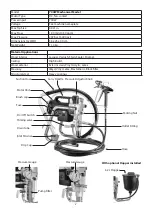
Summary of Contents for 700W Mechanical

Page 1: ...Original Instructions ...

Page 2: ...tor Type DC fan cooled Power input 700W Voltage See machine nameplate Max Tip Size 0 021in Max Flow 1 9 l min 0 50 gpm Max Pressure 207 bar 3 000 psi Dimensions LxWxH 36 x 25 x 40 cm Net Weight 11 4 kg Suction Hose Drain Tube Brush cap Inlet Strainer Carry Handle Priming valve Packing Nut Fuse On Off Switch Pressure Adjustor Knob Motor Unit Outlet Fitting With optional Hopper installed 6 2L Hopper...

Page 3: ...uch as pipes radiators ranges and refrigerators There is an increased risk of electric shock if your body is earthed or grounded 4 Do not expose power tools to rain or wet conditions Water entering a power tool will increase the risk of electric shock 5 Do not abuse the cord Never use the cord for carrying pulling or unplugging the power tool Keep the cord away from heat oil sharp edges or moving ...

Page 4: ...f moving parts breakage of parts and any other condition that may affect the power tool s operation If damaged have the power tool repaired before use Many accidents are caused by poorly maintained power tools 6 Keep cutting tools sharp and clean Properly maintained cutting tools with sharp cutting edges are less likely to bind and are easier to control 7 Use the power tool accessories and tool bi...

Page 5: ...y of the points to which he has access that the plug remains removed WARNING HIGH PRESSURE Never leave pressurized system unattended Always follow the Pressure Relief Procedure Take precautions to avoid high pressure component rupture DANGER INJECTION INJURY Skin injection by high pressure paint is not a simple cut It must be treated surgically immediately WARNING FIRE AND EXPLOSION HAZARD Take al...

Page 6: ...Paint will penetrate through these materials into the hand NEVER try to stop or deflect leaks with your hand or body ALWAYS have the tip guard in place when spraying ALWAYS lock the gun trigger when you stop spraying ALWAYS remove tip from the gun to clean it NEVER try to blow back paint this is not an air powered sprayer ALWAYS follow the PRESSURE RELIEF PROCEDURE before cleaning or removing the ...

Page 7: ...rotective eyewear gloves clothing and respirator as recommended by fluid manufacturer HOSES Tighten all of the fluid connections securely before each use High pressure fluid can dislodge a loose coupling or allow high pressure spray to be emitted from the coupling and result in an injection injury or serious bodily injury Only use hoses with a spring guard The spring guard helps protect the hose f...

Page 8: ... the spray unit paint bucket spraying object See GROUNDING Use only high pressure airless hoses approved for 3000 psi which is conductive 3 Remove the spray tip before flushing Hold the metal part of the gun firmly to the side of a metal pail use the lowest possible fluid pressure during flushing 4 Never use high pressure in the cleaning process USE MINIMUM PRESSURE 5 Do not smoke in spraying clea...

Page 9: ...utdoor use OPERATION Before beginning always check and tighten all fittings securely WARNING A loose connection could burst loose under pressure causing a hazardous condition Ensure that all connections are tight This includes both ends of the hose the gun filter the tip guard the pump filter and the suction tube gland nut WARNING Always ensure that the gun safety latch is in the locked position T...

Page 10: ...ed from the gun point the gun into the waste bucket and hold the trigger open WARNING Risk of static sparking fire or explosion Hold the metal part of the gun firmly to the side of a metal pail All solvent pails must be conductive metal material and properly grounded Do not place on a non conductive insulating surface unless a ground wire is added to a true earth such as a metal water pipe 9 Close...

Page 11: ...n the seat and insert the seat into the tip guard Make sure that it is aligned to the circular opening in the tip guard 3 3 Thread the tip guard onto the gun finger tight only 4 Insert the tip into the tip guard and ensure that it is fully home Rotate the tip all the way to the forward position the arrow on the tip handle will point forward The tip can be rotated 180 degrees for clearing clogs 5 T...

Page 12: ...thin the material Do not raise the pressure any higher than is necessary Operating the sprayer at a higher than necessary pressure wastes material causes early tip wear and shortens sprayer life Excessive pressure can also result in bounce back of the material and a rough finish Running with the pressure at the absolute maximum setting will also make the pump run on and off in an irregular way NOT...

Page 13: ... is brittle and can chip Forward position for spraying Reversed position for clearing clogs Never attempt to spray with the tip in any position other than fully forward or fully reversed A General Guide for Tip Sizes Flow Rates and Pressures at the Gun chart 1 Material Atomization Pressure at the gun Min RequiredFlow Rate Tip Size Recommended Hose Lacquer semi transparent stains 1300 PSI 90 BAR 0 ...

Page 14: ...lly use a smaller orifice tip For light viscosities thin materials like varnish and use a larger orifice tip for heavier viscosities thicker materials like latex paints Spray tip orifice size is based on how many gallons of paint per minute can be sprayed through the tip Do not use a tip larger than the maximum pump flow rate or capacity the sprayer can accommodate Pump flow rate is measured in ga...

Page 15: ...the waste bucket next to it WARNING Do not release the gun trigger during this process If you release the trigger pressure will build in the line and when you re squeeze the trigger there will be a splashback hazard 12 Keep the trigger held open and allow the pump to run and watch the fluid discharging from the gun Allow the fluid to discharge until all traces of material are gone and pure flushin...

Page 16: ...t should be tightened just enough to stop leakage only but not any tighter Overtightening will damage the packings and reduce packing life 3 Clean the intake check ball and seat housing Place the filter in the spray gun and reassemble the unit by tightening the nut with the wrench 19 Clean the exterior of the sprayer with a rag soaked in the appropriate solvent 20 If flushing was with water flush ...

Page 17: ... remove the 4 socket cap screws 65 4 Pull the pump forward to disengage the displacement piston 53 from the slot in the bottom of the drive piston 45 It must be at its lowest point in order to disengage see step 2 above 5 The pump unit may now be lifted away 6 Replacement is the reverse of removal Grease the junction slot of the drive piston when assembling PACKINGS REPLACEMENT 1 Loosen the packin...

Page 18: ...usted to an authorized service center Incorrectly performed repairs could lead to injury or death O P T I O N A L P R E S S U R E G A U G E INSTALLATION INSTRUCTIONS 1 Remove the hose and output nipple fitting from the pump 2 Add 3 turns of thread seal tape and then thread on the pressure gauge T fitting 3 Add 3 turns of thread seal tape and then thread on the output fitting in line with the flare...

Page 19: ...drain hose onto the fitting and tighten with a wrench 4 Remove the suction hose by squeezing the hose clip and pulling straight down 5 Insert the hopper s suction pipe fully into the pump and then squeeze the hose clip and ensure that it seats fully in the slot 6 Thread the hopper onto the suction pipe 7 Insert the strainer into the bottom of the hopper NO 01 07 V 1 0 NO Parts Name Q TY 1 PLASTIC ...

Page 20: ...re problems Check Solution Clogged tip or filter Relieve pressure and clean Problem Motor cannot maintain pressure Check Solution Oversized tip Use correct tip for spayer Tip worn to become oversize Relieve pressure and replace tip Problem Low output Check Solution Worn tip Relieve pressure and replace tip Worn packings Replace packings Filter clogged Relieve pressure and Clean filter Priming valv...

Page 21: ...21 WIRING AC 1 2 4 5 BRUSH BLUE BLUE BLACK WHITE BLUE BROWN BROWN BLUE BROWN BLUE BRUSH WHITE WHITE BLUE NEGATIVE BROWN POSITIVE FUSE PLATE POWER SWITCH ELECTRONICS BOX PRESSURE SWITCH ...

Page 22: ...4 43 57 70 69 67 66 65 03 27 28 27 28 37 36 34 38 39 35 32 31 29 30 76 75 77 75 42 80 79 42 26A 26B MOTOR 110V MOTOR 220V 50 58 59 78 68 51 45 04 19 19 64 11 13 22 24 23 40 41 74 71 13 12 33 72 85 10 09 82 83 84 OPTIONAL 62 63 60 A2 OPTIONAL to 58 A2 2 A2 1 A1 1 A1 OPTIONAL to 58 A1 2 A1 3 A1 4 A1 5 A1 6 A1 7 73 61 ...

Page 23: ...M5 x 25 4 43 BUSHING Ø26 x Ø32 x 30 1 44 EXTERNAL CIRCLIP IR 32 1 45 DRIVE PISTON 1 46 PUMPWRIST PIN Ø10 x 23 5 1 47 PACKING NUT 1 NO Parts Name Q TY 48 SEAL SEAT 1 49 O RING S 31 5 1 50 O RING Ø31 2 x Ø35 1 x 1 8 1 51 CHECK BALL PISTON PACKING 1 52 DISC SPRING 3 53 DISPLACEMENT PISTON 1 54 BALL SEAT Ø4 x Ø13 8 x 4 1 55 O RING 1 56 BALL SEAT FASTENER M16 1 57 PACKING SPACER 1 58 PUMP HOUSING 1 59 ...

Page 24: ......

Reviews: