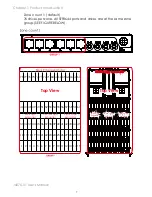
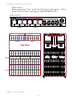
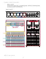
AIC J4076-01, User Manual
Looking for the user manual for AIC J4076-01? Look no further! The manual is available for free download from 88.208.23.73:8080, providing you with all the necessary information to operate your product efficiently. Don't hesitate to get your hands on the manual today!
Share
Download


Reviews:
No comments
Related manuals for J4076-01

ARX-2000
Brand: F5 Pages: 32

Viprion
Brand: F5 Pages: 74

P13R
Brand: Magma Pages: 52

5Y08
Brand: Premier Pages: 30
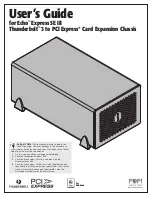
Echo Express SE III
Brand: Sonnet Pages: 14
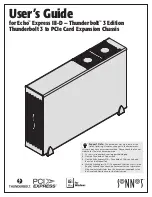
Echo Express III-D Thunderbolt 3 Edition
Brand: Sonnet Pages: 14
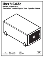
echo express SE II
Brand: Sonnet Pages: 16
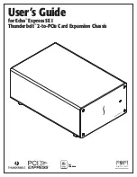
Echo Express SE I
Brand: Sonnet Pages: 16

MB6
Brand: Haivision Pages: 29

YY-R226
Brand: Yeong Yang Pages: 4

PXI-1031DC
Brand: National Instruments Pages: 64

QV14.1E
Brand: Philips Pages: 244

Raven MIL-RCM16A
Brand: MiLAN Pages: 53

E1M4
Brand: iStarUSA Pages: 3

E2M8
Brand: iStarUSA Pages: 3

D-400-7
Brand: iStarUSA Pages: 3

D-400-7P
Brand: iStarUSA Pages: 3

D-414
Brand: iStarUSA Pages: 3


