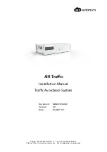
background image

air

avionics

AIR Traffic

Installation Manual

Traffic Avoidance System

Document:

MAN0070A0001

Version:

4.0

Date:

2020/01/09

Phone: +49 (0) 6224 82 83 87 0

·

Fax: +49 (0) 6224 82 83 87 7

Internet: https://www.air-avionics.com

·

Mail: support@air-avionics.com

Summary of Contents for AIR Traffic

Page 1: ...affic Installation Manual Traffic Avoidance System Document MAN0070A0001 Version 4 0 Date 2020 01 09 Phone 49 0 6224 82 83 87 0 Fax 49 0 6224 82 83 87 7 Internet https www air avionics com Mail suppor...

Page 2: ...air avionics 2 AT 1 Installation Manual rev 4 0 2020 01 09...

Page 3: ...l information and functions have been added 2 1 2018 12 21 Release M F rderer Added details regarding ARINC429 and discrete inputs 2 2 2019 03 15 Release M F rderer Added ICA fixed some minor issues 3...

Page 4: ...Connectors 10 Static Pressure Port 11 Interfaces 12 Serial Data Interface 12 ARINC429 Interface 13 WiFi Interface 13 Data Bus Interface 13 Power Supply and Enable Interface 14 Audio Output 16 Discrete...

Page 5: ...Simple Advanced and Expert Configuration Mode 38 Simple Configuration 39 Expert Configuration 40 Ground Checks 41 Simulator for Ground Checks 41 Interface Checkout 41 Discrete Inputs Check 42 Audio C...

Page 6: ...ce Checks 59 Documentation 59 Configuration Parameters 60 Own Aircraft 60 Installation 61 Privacy 62 Warnings 63 Digital and Analog Inputs 67 Audio Output 69 Relay 70 Flight Data Recorder 71 WiFi Inte...

Page 7: ...air avionics Contents AT1 Software Version 3 104 AT1 Software Version 2 106 AT1 Software Version 1 107 Environmental data 108 AT 1 Installation Manual rev 4 0 2020 01 09 v...

Page 8: ...Contents air avionics vi AT 1 Installation Manual rev 4 0 2020 01 09...

Page 9: ...tandard aviation maintenance practices in accordance with relevant accepted practices This manual is not intended for use by individuals who do not possess the competencies and abilities set forth abo...

Page 10: ...pprovals CS STAN or specific EASA Minor Change Approvals or Supplementary Type Certificates STC that have been created by AIR Avionics or third party organisations AT 1cannotbeusedasareplacementforcer...

Page 11: ...Connector rpSMA FLARM Antenna Connector A SMA FLARM Antenna Connector B SMA WiFi Antenna Figure 1 2 Housing and connector overview 1 5 Regulatory Compliance 1 5 1 ETSO Functions AT 1 does not cover a...

Page 12: ...1 1 EN 301 489 17 V3 1 1 EN 300 328 V2 1 1 EMC EN 55022 2010 AC 2011 1 5 5 Limitations AT 1 is subject to various limitations Operational limitations can be reviewed in the AT 1 Pilot s Manual 1 AT 1...

Page 13: ...HD crimp connector backshell and contacts 1 x FLARM Cockpit Antenna B571 FLARM Antenna for cockpit installation SMA 1 x 1090 Cockpit Antenna B572 ADS B XPDR Antenna for cockpit installation rpSMA 1 x...

Page 14: ...re eu Part numbe Description B569 D SUB26HD connection kit with receptacle backshell crimp terminals wire B427 1m cable to AIR Traffic Displays ATD 11 57 80 with power supply leads B428 3m cable to AI...

Page 15: ...or B SMA Female Figure 2 1 System interconnects overview 2 1 D SUB Power Data Connectors Both data connectors are D SUB high density types Connector one is a D SUB26 HD male connector with 26 pins con...

Page 16: ...rcraft Power VIN 1 10 In RS 232 Port 1 transmit data TXD1 1 11 Out RS 232 Port 2 transmit data RXD2 1 12 Out RS 232 Port 3 transmit data TXD3 1 13 Out Power Output 3 3V 3v3out 1 14 Out Audio Output AU...

Page 17: ...Bus Low Signal CANLO 2 7 In Out Data Bus High Signal CANHI 2 8 In Out Not Connected 2 9 Not Connected 2 10 Not Connected 2 11 Not Connected 2 12 Not Connected 2 13 Aircraft Ground GND 2 14 Not Connect...

Page 18: ...ors AT 1 features four antenna connectors The connectors have different polarity for FLARM 1090 MHz and GPS Please make sure to always connect the connectors correctly A wrong connection may damage th...

Page 19: ...essure port using an optional static pressure port connector Figure 2 6 The static port pressure connector can be optionally installed The static port adapter fits most aviaition standard tubings an h...

Page 20: ...connection is mandatory Theuseofatwistedpairshieldedcable e g MIL C 27500 22TG2T14ishighlyrecommended With this cable both data wires and the GND reference can be connected using a single cable SYSTE...

Page 21: ...A 1 24 Out ARINC429 Out B 1 25 Out The ARINC429 interface consists of two data wires The differential high speed signal requires twisted pair shielded cables e g MIL C 27500 22TG 2T14 3 3 WiFi Interf...

Page 22: ...requires impedance controlled shielded cables or at least twisted pair shielded cables The data bus interface requires termination resistors to be installed on each end of the bus 120 Ohm On connector...

Page 23: ...r output The output pins directly connect to the VIN pins on connector 1 Its main intention is to supply an AIR Traffic Display ATD 11 ATD 57 or ATD 80 if the AT 1 is directly attached to such a displ...

Page 24: ...a voice output traffic warnings status messages or a beep tone sine wave The audio output volume level is adjustable by means of a configuration parameter permanently configured to a certain level or...

Page 25: ...oggle switch NO ALARMS Traffic warnings issued over the AT 1 data Toggle switch interfaces can be suppressed ON GND In this case the switch sets the aircraft s Airframe switch WOW state as on the grou...

Page 26: ...ly processes toachievethedesireddurabilityandreliabilityforsubassemblyinterconnections specifically thoseinprintedwiringassembliesandcableharnesses andtheuseofinspectiontechniques and criteria to assu...

Page 27: ...tected area of the aircraft Do not route cable near high voltage sources For the D SUB connectors crimp terminals and mating receptacles are recommended because these are more reliable than soldered c...

Page 28: ...0 times weaker than a VHF radio Therefore especially the FLARM antenna installation is crucial Please ensure that all of the below mentioned requirements are met as closely as possible FLARM Cockpit A...

Page 29: ...windows or windshields that allow vertical installation of the antenna For example in Cessna Piper aircraft a good place would be on the side of the front windshield with adequate distance to metal s...

Page 30: ...t as possible Only experts with professional tools may shorten the FLARM antenna cable 4 Ensure that no conductive parts metal carbon fiber are close to the antenna on the outside 5 Install the antenn...

Page 31: ...a has to be mounted on a conductive surface of at least 20cm in diameter Always install FLARM antennas vertically 1 1 Figure 4 3 External antenna dual FLARM antenna setup Figure 4 4 External antenna r...

Page 32: ...rthogonal way in the first 15 cm 6 inches or use angled antenna connectors for external antennas 3 Do not coil the antenna cable 4 Ensure that no conductive parts metal carbon fiber are close to the a...

Page 33: ...ally on a conductive surface of at least a 15 cm 6 inches diameter 2 Ensure that the antenna cable is routed away from the antenna in an orthogonal way in the first 15 cm 6 inches or use angled antenn...

Page 34: ...It can be installed on the instrument panel glare shield or any other place with unobstructed view of the sky Good GPS performance is important for correct operation Please make sure that the requirem...

Page 35: ...ld be installed in accordance with applicable regulations Route the tubing as appropriate Avoid sharp bends Make sure the aircraft static pressure port is plumbed directly to the unit static pressure...

Page 36: ...than traffic data and therefore the system state is not shown to the flight crew If there is no system in your installation that is capable of displaying status messages please install AT 1 in a posit...

Page 37: ...ed devices compatibility must be assessed on a per installation level Not all functions supported by AT 1 are supported by all compatible devices For example not all configuration parameters can be se...

Page 38: ...compatible G3X G3X touch Tested GARMIN RS232 TIS Limited Skyview Tested Dynon RS232 TIS Limited None of the above mentioned systems is capable of displaying FLARM obstacle or FLARM alert zone warnings...

Page 39: ...ing However lower operating temperatures extend equipment life Reducing the operating temperature extends the mean time between failures MTBF Units tightly installed heat each other through radiation...

Page 40: ...les for the AT 1 mounting tray 2 Install the mounting tray in your aircraft Ensure there is sufficient space for the AT 1 main unit and all of the required cables and connectors 3 Install the device i...

Page 41: ...unted in a tray with dimensions 5 1 2 Using an AIR Traffic Display ATD 57 or ATD 80 In order to install the AT 1 on an AIR Traffic Display 57 ATD 57 a mounting kit with bracket and small parts is requ...

Page 42: ...2 Install the AT 1 mounting bracket on the ATD Connect connector 2 of AT 1 to the lower rear connector connector 2 of ATD 3 Use the supplied screws to secure AT 1 on the ATD install the ATD AT 1 combi...

Page 43: ...tions 2 Organise and secure all antenna cables 5 4 Interconnect Installation 1 Install all electrical connectors and ensure that they are appropriately secured 2 Install the antenna connectors and ens...

Page 44: ...a continuity check perform power and ground checks to verify that proper power and GND levels are present Any faults or discrepancies must be corrected at this time Any faults or discrepancies must be...

Page 45: ...T 1 Configuration Webpage The AT 1 configuration webpage is accessible via any WiFi capable device such as a PC a smartphone or a tablet referred to as a personal device here Please follow these steps...

Page 46: ...anced and expert configuration modes will negatively affect device performance if not set correctly In the advanced configuration mode more parameters are configurable In the expert configuration mode...

Page 47: ...code is mandatory for AT 1 to function properly If your aircraft does not have an ICAO address e g because you do not have a Mode S transponder or 406MHz ELT installed and no ID has been assigned to y...

Page 48: ...ta port 2 This data port is normally used to provide other avionics systems for example traffic displays with traffic data Therefore by default this data port transmits traffic data in the FLARM proto...

Page 49: ...deactivated 8 2 Interface Checkout 8 2 1 Serial Interface Check The serial data interface of the unit can be checked with a pragmatic function test 1 Connect AT 1 and another compatible avionics syste...

Page 50: ...follows 1 Start the simulator mode on the AT 1 configuration webpage 2 The data connection to your aviation app does not work while the AT 1 configuration webpage is open Close the AT 1 configuration...

Page 51: ...ew version information on AT 1 configuration webpage via WiFi 8 6 Traffic reception tests Verify that the AT 1 is receiving traffic while on the ground A pragmatic test using a connected traffic displ...

Page 52: ...nd corresponding error messages please consult the AIR Avionics Error Message index 9 1 Status LED 9 1 1 LED Positions The device status of the AT 1 is shown using three multi color LEDs located in th...

Page 53: ...een ADS B Transponder Normal Operation Status LED 2 Status LED 2 Pattern LED 2 Color Fatal error failure FLARM transceiver red module unavailable FLARM software incompatible or expired red Last datase...

Page 54: ...r 3 seconds ago Reduced function error affecting traffic data processing and warnings For example yellow no barometric pressure data is available Reduced function error not directly affecting traffic...

Page 55: ...lue red failed file syntax Writing log file to USB blue off blue USB thumb drive Writing log file to USB blue green blue successfully finished Writing log file to USB blue red blue failed Initiating m...

Page 56: ...enta magenta magenta incompatible application Bootloader processing a magenta magenta magenta software container file Bootloader is installing magenta magenta magenta application Bootloader has finish...

Page 57: ...air avionics 9 System Status and Error Messages Figure 9 2 Screenshot of the Device Info section in the AT 1 configuration web page AT 1 Installation Manual rev 4 0 2020 01 09 49...

Page 58: ...es a print button for easier configuration log ging Open the configuration webpage as described in section 7 1 1 then use the Print this Page button to print a copy of the entire system configuration...

Page 59: ...with AT 1 and normally installed into the aircraft Never remove the USB thumb drive while the device is booting The device s software may stop working In this case a system restart would be required...

Page 60: ...database file onto a USB thumb drive into the root folder main folder no subfolder 3 Insert the USB thumb drive into the AT 1 or the jack of the installed USB extension cable while AT 1 is powered off...

Page 61: ...Bibliography A 1 AIR Avionics AT 1 Pilot s Manual EN August 2018 AT 1 Installation Manual rev 4 0 2020 01 09 53...

Page 62: ...B Assembly And Installation Drawings 61 50 131 15 122 30 75 Figure B 1 Dimensional drawing all dimensions in millimeters 54 AT 1 Installation Manual rev 4 0 2020 01 09...

Page 63: ...ote that the GTN is only capable of displaying traffic on the map if it is connected to a heading source Depending on requirements AT 1 can be used as a heading source Please see the expert configurat...

Page 64: ...NS is only capable of displaying traffic on the map if it is connected to a heading source Depending on requirements AT 1 can be used as a heading source Please see the expert configuration mode param...

Page 65: ...A GPS USB TYPE A CONNECTOR USB THUMB DRIVE COAXIAL CABLE 1 USB TYPE C CONNECTOR Power Out VOUT Power Out VOUT Aircraft Ground GND Aircraft Ground GND Enable EN RS 232 Port 2 transmit data TXD2 RS 232...

Page 66: ...eive Data RXD2 RS 232 Port 2 Transmit Data TXD2 RS 232 Port 3 Receive Data RXD3 RS 232 Port 3 Transmit Data TXD3 Data Bus Low Signal CANLO Data Bus High Signal CANHI Data Bus Termination 120 OHM CANTE...

Page 67: ...has been performed Check not required 6 Audio check has been performed Check not required 7 Version check has been performed 8 Traffic reception check has been performed 9 Failure message check has be...

Page 68: ...do not have a Mode S Transponder or 406MHz ELT installed and therefore no ID has been assigned to your aircraft yet please enter FFFFFF instead Item Code ACFTADDR Valid Values 6 digit hex number Defau...

Page 69: ...track estimation However the fallback value is used only if valid GPS data is available Item Code GPSTRKFALLBACK Valid Values NONE TRUENORTH Default Value NONE F 2 3 1090MHz Receiver Attenuation Descr...

Page 70: ...iderNet Item Code FLARMNOTRACK Valid Values ON OFF Default Value OFF F 3 2 Stealth Mode Description Enables the FLARM Stealth Mode If enabled your own aircraft s FLARM data will be obscured from other...

Page 71: ...me independent from flight vectors a certain threat level is set for any traffic target Protection Volume 1 has the highest priority It overrules all other protection volumes Be very careful Do not ch...

Page 72: ...ghest priority It overrules all other protection volumes except protection volume 1 Be very careful Do not change this value unless you know exactly what you are doing Adjusting this parameter wrongly...

Page 73: ...PROTECTRANGE3 Valid Values integer value 0 1000000 Default Value 0 F 4 10 Protection Volume 3 Vertical Range m Description Adjusts the vertical size of the protection volume 3 Inside this volume inde...

Page 74: ...volume independent from flight vectors a certain threat level is set for any traffic target Protection Volume 4 has the lowest priority It is overruled by all other other protection volumes Be very c...

Page 75: ...ut can either be active when low pulled to GND or when open floating Item Code DIN1POL Valid Values ACTLOW ACTOPEN Default Value ACTLOW F 5 3 Digital Input 2 Function Description Selects the function...

Page 76: ...th reduced warning sensitivity The VOICE ACKNOWLEDGE option allows to acknowledge the current spoken message Item Code DIN3FUNC Valid Values UNUSED MUTE NOALARM ONGND APPROACH VOICEACK Default Value U...

Page 77: ...affic display in the aircraft Item Code AUDIOSRC Valid Values PORT1 PORT2 PORT3 WIFI ARINC429 Default Value PORT2 F 6 3 Audio Output Volume Description Sets the volume of the audio signal emitted by t...

Page 78: ...UNUSED F 7 2 Relay Volume Range m Description Sets the horizontal dimension of the relay volume inside of which a target triggers the relay to be opened or closed depending on its configuration Item...

Page 79: ...t Data Recorder F 8 1 Flightlog Format Description Selects the file format in use while downloading flight files onto the USB thumb drive Item Code FLIGHTLOGFORMAT Valid Values IGC KML Default Value K...

Page 80: ...ation webpage via WiFi inaccessible Item Code WIFIENABLE Valid Values ON 15MIN OFF Default Value ON F 9 2 WiFi Interface Flarm Traffic Description Activates or deactivates the output of Flarm traffic...

Page 81: ...EW Valid Values integer value 0 1000000 Default Value 3000 F 9 7 WiFi Interface Non Bearing Vertical Range m Description Vertical range limit Non bearing targets outside of this range are not transmit...

Page 82: ...12 WiFi Interface PGRMZ Description Activates the output of the PGRMZ dataset PGRMZ is a dataset for pressure altitude Item Code NMEAPGRMZW Valid Values ON OFF Default Value ON F 9 13 WiFi Interface P...

Page 83: ...ion dataset in the FLARM data protocol Item Code NMEAPFLAQW Valid Values ON OFF Default Value ON F 9 17 WiFi Interface PFLAE Description Activates the output of the PFLAE dataset PFLAE is a failure er...

Page 84: ...ing Field is recommended Only set to Rotate Bearing if the connected traffic display on this interface does not support datasets with empty bearing data fields Item Code NMEAPFLAUNONDIRW Valid Values...

Page 85: ...LAA datasets Item Code NMEAPFLAANOTRACKW Valid Values ON OFF Default Value ON F 9 26 WiFi Interface PFLAE Error Messages Description Activates the output of error messages within the PFLAE dataset In...

Page 86: ...port 1 Range m Description Horizontal range limit Targets outside of this range are not transmitted over this data output Item Code RANGE1 Valid Values integer value 0 1000000 Default Value 25000 F 1...

Page 87: ...l for this data interface Item Code PROTOCOL1 Valid Values NMEA GARMINTIS GDL90 ABSTXT Default Value NMEA F 10 8 RS 232 data port 1 RS 232 Data Rate Description Selects the RS 232 data rate baud rate...

Page 88: ...for pressure altitude Item Code NMEAPGRMZ1 Valid Values ON OFF Default Value OFF F 10 13 RS 232 data port 1 PFLAU Description Activates the output of the PFLAU dataset PFLAU is a warning dataset in th...

Page 89: ...0 17 RS 232 data port 1 PFLAE Description Activates the output of the PFLAE dataset PFLAE is a failure error annunciation dataset in the FLARM data protocol Item Code NMEAPFLAE1 Valid Values ON OFF De...

Page 90: ...not support datasets with empty bearing data fields Item Code NMEAPFLAUNONDIR1 Valid Values OFF EMPTYBRG ROTATE Default Value OFF F 10 22 RS 232 data port 1 PFLAU Alert Zones Description Activates war...

Page 91: ...d Values ON OFF Default Value ON F 10 26 RS 232 data port 1 PFLAE Error Messages Description Activates the output of error messages within the PFLAE dataset In addition to the error itself an error me...

Page 92: ...port 2 Range m Description Horizontal range limit Targets outside of this range are not transmitted over this data output Item Code RANGE2 Valid Values integer value 0 1000000 Default Value 25000 F 1...

Page 93: ...for this data interface Item Code PROTOCOL2 Valid Values NMEA GARMINTIS GDL90 ABSTXT Default Value NMEA F 11 8 RS 232 data port 2 RS 232 Data Rate Description Selects the RS 232 data rate baud rate f...

Page 94: ...for pressure altitude Item Code NMEAPGRMZ2 Valid Values ON OFF Default Value ON F 11 13 RS 232 data port 2 PFLAU Description Activates the output of the PFLAU dataset PFLAU is a warning dataset in th...

Page 95: ...17 RS 232 data port 2 PFLAE Description Activates the output of the PFLAE dataset PFLAE is a failure error annunciation dataset in the FLARM data protocol Item Code NMEAPFLAE2 Valid Values ON OFF Def...

Page 96: ...not support datasets with empty bearing data fields Item Code NMEAPFLAUNONDIR2 Valid Values OFF EMPTYBRG ROTATE Default Value OFF F 11 22 RS 232 data port 2 PFLAU Alert Zones Description Activates war...

Page 97: ...d Values ON OFF Default Value ON F 11 26 RS 232 data port 2 PFLAE Error Messages Description Activates the output of error messages within the PFLAE dataset In addition to the error itself an error me...

Page 98: ...port 3 Range m Description Horizontal range limit Targets outside of this range are not transmitted over this data output Item Code RANGE3 Valid Values integer value 0 1000000 Default Value 25000 F 1...

Page 99: ...or this data interface Item Code PROTOCOL3 Valid Values NMEA GARMINTIS GDL90 ABSTXT Default Value GARMINTIS F 12 8 RS 232 data port 3 RS 232 Data Rate Description Selects the RS 232 data rate baud rat...

Page 100: ...for pressure altitude Item Code NMEAPGRMZ3 Valid Values ON OFF Default Value ON F 12 13 RS 232 data port 3 PFLAU Description Activates the output of the PFLAU dataset PFLAU is a warning dataset in th...

Page 101: ...2 17 RS 232 data port 3 PFLAE Description Activates the output of the PFLAE dataset PFLAE is a failure error annunciation dataset in the FLARM data protocol Item Code NMEAPFLAE3 Valid Values ON OFF De...

Page 102: ...ot support datasets with empty bearing data fields Item Code NMEAPFLAUNONDIR3 Valid Values OFF EMPTYBRG ROTATE Default Value OFF F 12 22 RS 232 data port 3 PFLAU Alert Zones Description Activates warn...

Page 103: ...d Values ON OFF Default Value ON F 12 26 RS 232 data port 3 PFLAE Error Messages Description Activates the output of error messages within the PFLAE dataset In addition to the error itself an error me...

Page 104: ...N F 13 3 ARINC429 Range m Description Horizontal range limit Targets outside of this range are not transmitted over the ARINC429 data output Item Code A429RANGE Valid Values integer value 0 1000000 De...

Page 105: ...creens If this option is activated AT 1 transmits a GPS track derived aircraft heading over the ARINC429 data output Under circumstances for example when the own aircraft is not moving this heading da...

Page 106: ...ule Software Version 3 FLARM Module Software Version 6 80 1090MHz Receiver Module Software Version G 1 2 Changes Since Version 7 Main Module Software Fixed an issue which could result in invalid altit...

Page 107: ...rsion 42 G 2 2 Changes Since Version 6 This software version only contains firmware for the integrated 1090MHz receiver module and can be applied any time Main Module Software This image contains no f...

Page 108: ...ns Main Module Software Version 5 WiFi Module Software Version 3 FLARM Module Software Version 6 80 1090MHz Receiver Module Software Version 38 G 3 2 Changes Since Version 5 Main Module Software Fixed...

Page 109: ...ot moving Added three additional protection volume configuration items PROTECTRANGEn PROTECTVRANGEn PROTECTLEVELn for configuration of warning behaviour within four volumes Added REQUESTCONFIG command...

Page 110: ...radio id type on the config website Show FLARM obstacle db status on the config website Corrected description of WARNONGND item on the config website Improved naming of items on the config website Fi...

Page 111: ...FLARM Module Software Version 6 62 1090MHz Receiver Module Software Version 38 G 5 2 Changes Since Version 3 Main Module Software Added support for hardware version 1100 1000 and 0100 WiFi Module Soft...

Page 112: ...e ONGND switch to force FLARM flight state Disable FLARM or 1090 receiver maintenance functions while AT 1 is in simulator mode Fixed minor bugs in the ARINC429 output Deactivated TCASActive flag if n...

Page 113: ...webpage Reordered ARINC429 interface items on configuration webpage to be consistent to logfile FLARM Module Software Updated FLARM core softwore from version 6 60 to version 6 62 1090MHz Receiver Mod...

Page 114: ...Module Software Version 6 60 1090MHz Receiver Module Software Version 38 G 7 2 Changes Since Version 1 Main Module Software No Changes WiFi Module Software No Changes FLARM Module Software Updated FL...

Page 115: ...Software Version 1 G 8 1 Component Versions Main Module Software Version 1 WiFi Module Software Version 1 FLARM Module Software Version 6 40 1090MHz Receiver Module Software Version 38 AT 1 Installati...

Page 116: ...not tested Fluids Susceptibilities 11 0 X not tested Sand and Dust 12 0 X not tested Fungus Resistance 13 0 X not tested Salt Spray 14 0 X not tested Magnetic Effect 15 0 Z Less than 0 3m Power Input...

Reviews: