
air
avionics
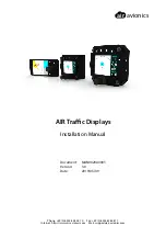
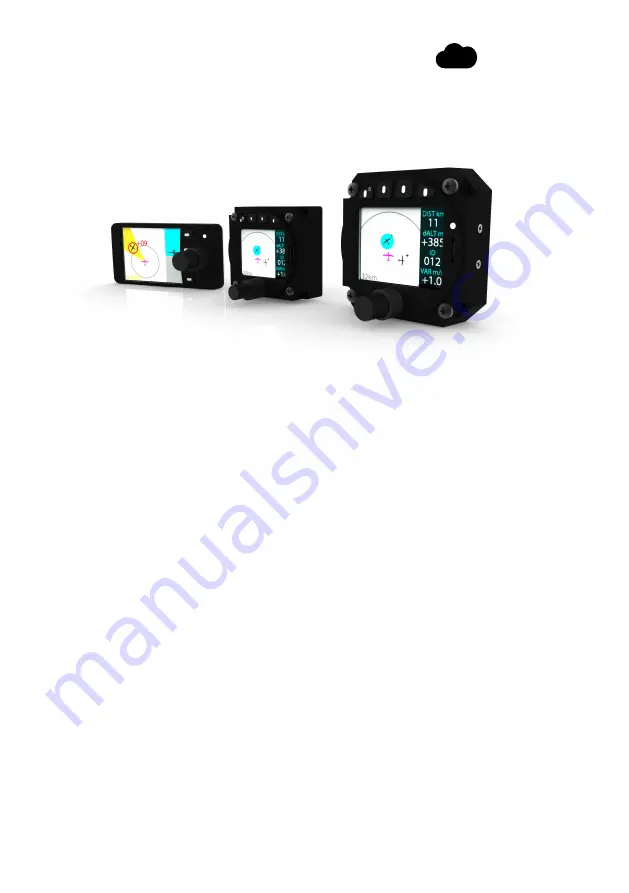
AIR Traffic Displays
Installation Manual
Document:
MAN0020A0003
Version:
3.0
Date:
2019/05/09
Phone: +49 (0) 6224 82 83 87 0
·
Fax: +49 (0) 6224 82 83 87 7
Internet: https://www.air-avionics.com
·
Mail: support@air-avionics.com
The Air Avionics ATD-11 is a state-of-the-art avionics system designed for aircraft. For detailed instructions on installing and operating this product, be sure to download the free Installation Manual from 88.208.23.73:8080. This comprehensive manual will guide you through the set-up process and ensure optimal performance.
air
avionics
AIR Traffic Displays
Installation Manual
Document:
MAN0020A0003
Version:
3.0
Date:
2019/05/09
Phone: +49 (0) 6224 82 83 87 0
·
Fax: +49 (0) 6224 82 83 87 7
Internet: https://www.air-avionics.com
·
Mail: support@air-avionics.com