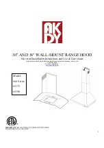
background image


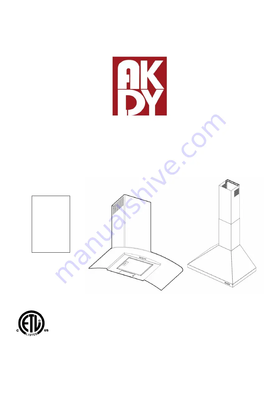
30" AND 36" WALL-MOUNT


RANGE HOOD 

Universal Installation Instructions and Use & Care Guide 

For questions about features, operation/performance parts, accessories or service, call: 

1-626-453-0550 

or visit our website at... 

www.akdytrading.net


IMPORTANT: READ AND SAVE THESE INSTRUCTIONS. 
FOR RESIDENTIAL USE ONLY. 

Model:  

668 Series 

63175 

63190 

Summary of Contents for 63175

Page 1: ...ions and Use Care Guide For questions about features operation performance parts accessories or service call 1 626 453 0550 or visit our website at www akdytrading net IMPORTANT READ AND SAVE THESE IN...

Page 2: ...17 WARRENTY SERVICES 19 RANGE HOOD SAFETY Your safety and the safety of others are very important We have provided many important safety messages in this manual and on your appliance Always read and o...

Page 3: ...ive materials and vapors CAUTION To reduce risk of fire and to properly exhaust air be sure to duct air outside do not vent exhaust air into spaces within walls or ceilings attics or into crawl spaces...

Page 4: ...y mounting bracket 1 Pc Installation manual 1 Set Chimney Cover 1 Set Metal grease filter 1 4 Pcs Air outlet 1 Set Exhaust pipe 1 Pc Hardware 1 Set LOCATION REQUIREMENTS IMPORTANT Observing all govern...

Page 5: ...tertop height B Hood height from ceiling to bottom of the range hood filter surface D A C B C Hood height 24 61 0 cm min from electric cooking surface 27 68 6 cm min from gas cooking surface suggested...

Page 6: ...low and a thermal break should be installed to minimize conduction of outside temper atures as part of the vent system The damper should be on the cold air side of the thermal break The break should b...

Page 7: ...alley Road Cleveland OH 44131 5575 A 120 volt 60 Hz AC only 15 amp fused electrical circuit is required If the house has aluminum wiring follow the procedure below 1 Connect a section of solid copper...

Page 8: ...ll where the range hood will be installed 2 Select a mounting height between a minimum of 24 61 0cm for an electric cooking surface a minimum of 27 68 6cm for a gas cooking surface and a suggested max...

Page 9: ...alling the hood See Venting Requirements section 2 Determine the required height for the home power supply cable and drill a 1 3 2 cm hole at this location 3 Run the home power supply cable according...

Page 10: ...t Hazard Use two or more people to move and install range hood Failure to do so can result in back or other injury A M4 x 65 Mounting screws B Mounting slots C M4 x 65 Lower mounting screws 2 Remove t...

Page 11: ...the flapper 2 Install exhaust pipe COMPLETE INSTALLATION FOR NON VENTED RECIRCULATING INSTALLATION ONLY Step 1 Do not install exhaust pipe remove the grease filters locate the blower inside the hood...

Page 12: ...overs push lower cover down onto hood and lift upper cover to ceiling and install with two M5 x 12 screws NOTE For vented installations the upper vent cover maybe reversed to hide slots A Upper chimne...

Page 13: ...fore cooking and allow it to operate several minutes after the cooking is complete to clear all smoke and odors from the kitchen A Chimney holes For non vented installation only B Chimney C Control pa...

Page 14: ...speed and sound level for quiet operation The speed can be changed anytime during fan operation by pressing the desired blower speed button The blower off button turns the blower off Adjusting the cl...

Page 15: ...ergent soap and water or all purpose cleanser Wipe with damp soft cloth or nonabrasive sponge then rinse with clean water and wipe dry Metal Grease Filter 1 Remove the filter by pulling the spring rel...

Page 16: ...eplacing the LED light Turn off the range hood and allow the LED to cool To avoid damage or decreasing the life of the new bulb do not touch bulb with bare fingers Replace bulb using tissue or wearing...

Page 17: ...verifying that the locking system in the connectors is well locked 4 If the connectors are not well connected Hold and press main connectors attached in the white plastic Push inwards the motor lamp...

Page 18: ...stic and that the locking system in the connectors is well locked 4 If the connectors are not well connected Hold and press main connectors attached in the white plastic Push inwards the motor lamp co...

Page 19: ...your major appliance if it is installed in an inaccessible location or is not installed in accordance with published installation instructions 10 Major appliances with original model serial numbers th...

Reviews: