background image


Video Cassette Recorder 

Service Manual


All manuals and user guides at all-guides.com

Summary of Contents for VCR-S608

Page 1: ...Video Cassette Recorder Service Manual All manuals and user guides at all guides com ...

Page 2: ... 2 Model No VCR S608 Version 1 0 MODEL VCR S608 All manuals and user guides at all guides com ...

Page 3: ... ALIGNMENT ADJUSTMENT 9 CABINET ASSEMBLY 21 ELECTRCAL PART LIST 27 BLOCK DIAGRAM 43 S M P S 46 POWER DRIVE 47 TIMER 48 SYSTEM CONTROL SERVO OSD 49 AUDIO VIDEO 50 HI FI OPTION 51 TM 52 SECAM OPTIONAL 53 A2 NICAM 54 INPUT OUTPUT 55 SUB 56 All manuals and user guides at all guides com ...

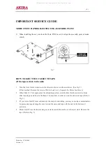
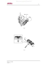
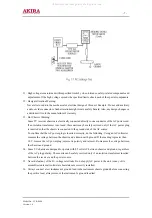
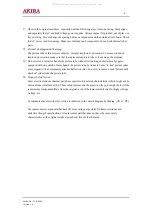
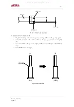
Page 4: ...Ass y Separate the Motor Load Ass y 2 When Slider S T are approaches the unloading position rotate holder Clutch counter clockwise after inserting screwdriver in the frame s bottom hole in order to wind the unwound tape Refer to Fig 3 3 If you rotate Gear Worm continuously when tape is unwinding you may cause tape contamination by grease and tape damage Be sure to wind the unwound tape with the un...

Page 5: ... 5 Model No VCR S608 Version 1 0 All manuals and user guides at all guides com ...

Page 6: ...handle brackets metal cabinets screw heads and control shafts The current measured should not exceed 0 5 milliamp Reverse the power plug prongs in the AC outlet and repeat the test 6 X ray Limits The picture tube is designed to prohibit X ray emissions To ensure continued X ray protection replace the picture tube only with one that is the same type as the original 7 Antenna Cold Check With the uni...

Page 7: ...nnected to the ground side of the AC source To confirm that the AC power plug is inserted correctly do the following Using an AC voltmeter measure the voltage between the chassis and a known earth ground If the reading is greater than 1 0V remove the AC power plug reverse its polarity and reinsert Re measure the voltage between the chassis and ground 14 Some TV chassis are designed to operate with...

Page 8: ... with side shields Never handle the picture tube by its neck Some in line picture tubes are equipped with a permanently attached deflection yoke do not try to remove such permanently attached yokes from the picture tube 20 Product Safety Notice Some electrical and mechanical parts have special safety related characteristics which might not be obvious from visual inspection These safety features an...

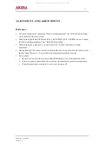
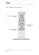
Page 9: ...er ass y be sure to adjust the X Point and Head switching adjustment 4 Among Samsung VCR remote control used for adjustment as an accessory only the remote control that has figures buttons 0 9 is available for all adjustment regardless of chassis 5 How to adjust a Momently short circuit th test point on Main PCB with pincers to set the adjustment mode b If the corresponding adjustment button is pr...

Page 10: ... 10 Model No VCR S608 Version 1 0 Location of adjustment button of remote control All manuals and user guides at all guides com ...

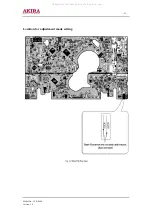
Page 11: ... 11 Model No VCR S608 Version 1 0 Location for adjustment mode setting All manuals and user guides at all guides com ...

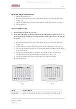
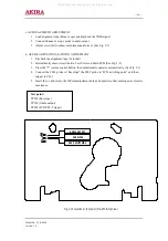
Page 12: ...ption is not set the unit will not operate 1 Momently short circuit the test point on Main PCB with pincers to set the adjustment mode See Fig 2 2 2 Press the MENU button on the remote control The option setting appears See Fig 2 3 3 Select the option number See table 2 1 of corresponding model with buttons on the remote control 4 After selecting the option number is completed press the button of ...

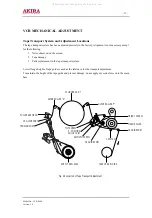
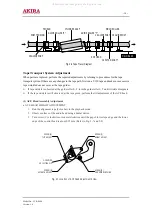
Page 13: ...em Lower flange height of tape guide is used as the reference for the transport adjustment To maintain the height of the tape guide and prevent damage do not apply excessive force onto the main base Fig 2 5 Location of Tape Transport Adjustment CYLINDER ASS Y TAKE UP REEL DISK 8 GUIDE POST 9 GUIDE POST SUPPLY REEL DISK CAPSTAN PINCH ROLLER GUIDE ROLLER T GUIDE ROLLER S FULL ERASE HEAD 3 GUIDE POST...

Page 14: ... 1 ACE Head Assembly Adjustment a ACE HEAD HEIGHT ADJUSTMENT 1 Run the alignment tape Color bar in the playback mode 2 Observe surface of the audio head using a dental mirror 3 Turn screw C clockwise or counterclockwise until the gap of lower tape edge and the lower edge of the control head is about 0 25mm Refer to Fig 2 7 and 2 8 Fig 2 6 Tape Travel Diagram POST TENSION MAIN BASE FE HEAD CYLINDER...

Page 15: ... no curl or wrinkle at the lower flange of tape guide as shown in Fig 2 9 B 3 If a curl or wrinkle of the tape occurs slightly turn the screw A tilt adjust on the ACE head ass y 4 Reconfirm the ACE head height Fig 2 8 ACE Head Height Adjustment 0 0 25 mm AUDIO HEAD VIDEO HEAD CONTROL HEAD Fig 2 9 Tape Guide Check A B BAD WRINKLE GOOD All manuals and user guides at all guides com ...

Page 16: ...it the two Test Points on Main PCB See Fig 2 2 3 Press the 5 remote control button then adjustment is operates automatically See Fig 2 1 4 Connect the CH 1 probe to Envelope the CH 2 probe to H D switching pulse and then trigger to CH 1 5 Insert the driver into the X Point adjustment hole and adjust it so that envelope waveform is maximum Test point TP301 Envelope TP302 Audio output TP602 H D S W ...

Page 17: ...mum output of the video RF envelope at the center point d Maximum output of the video RF envelope at the exit side 4 If the section A in Fig 2 12 does not meet the specification adjust the guide roller S up or down 5 If the section B in Fig 2 12 does not meet the specification adjust the guide roller T up or down 6 Play back the Mono Scope alignment tape SP mode 7 Connect an oscilloscope CH 1 to t...

Page 18: ...uide Roller S T Height Adjustment IDEAL ENVELOPE SHEIGHTTOOHIGH SHEIGHTTOOLOW THEIGHTTOOHIGH THEIGHTTOOLOW GUIDE ROLLER S GUIDE ROLLER T Fig 2 12 Adjustment Points A B A B H D SWITCHING PULSE ENVELOPE All manuals and user guides at all guides com ...

Page 19: ... 3 Change operation mode from the RPS to the play mode again and make sure the entry side of envelope rises within 3 seconds 4 Envelope Check 1 Make recordings on T 120 E 120 and T 160 E 180 tape Make sure the playback output envelope meets the specification as shown in Fig 2 15 2 Play back a self recorded tape recording made on the unit using with T 120 E 120 The video envelope should meet the sp...

Page 20: ... rotation of the capstan motor causes the holder clutch ass y to rotate through the belt pulley 2 The spring wrap PLAY REV of holder clutch ass y drives the disk reel S T through gear idler by rotation of gear center ass y 3 Brake is operated by slider cam at FF REW mode 4 Transportation of accurate driving force is done by gears Gear Center Ass y Note If the specification does not meet the follow...

Page 21: ... 21 Model No VCR S608 Version 1 0 CABINET ASSEMBLY All manuals and user guides at all guides com ...

Page 22: ...T TOP P001 Refer to table below ASSY PCB MAIN P020 Refer to table below CONNECTOR BOARD P025 AC39 10019A CBF POWER CORD KKP 419C H03VVH2 F VDE KE W001 6003 000275 SCREW TAPTITE BH B M3 L10 BLK SWCH101 W006 AC60 12126A SCREW BH FE FZY BH 4 12 W007 AC60 10063A SCREW TAPTITE L12 ZPC3 M3 SWRC Model A001 C001 C003 C015 VCR S608 S AC59 00071A AC97 02322A AC64 01375A AC64 01306A Model P001 P020 T001 VCR ...

Page 23: ... 23 Model No VCR S608 Version 1 0 Mechanical Parts Top Side All manuals and user guides at all guides com ...

Page 24: ...FOR X T016 AC97 02215A ASSY POST 8 GUIDE SUS303 POM M90 44 EQ T019 AC66 10267A REEL DISK S X 9 POM T020 AC66 10268A REEL DISK T X 9 POM T021 AC66 30524A LEVER IDLER POM BLK T022 AC66 00039A GEAR IDLE TS 10 PET K3372 0 5 NTR 28 T023 AC66 00035A LEVER TENSION ASS Y TS 10 SECC E20 20 SU T024 AC61 00107A SPRING ETC TENSION LEVER TS 10 SUS304 WP T025 AC69 00104A BAND BRAKE ASS Y TS 10 T026 AC66 30550A ...

Page 25: ... 25 Model No VCR S608 Version 1 0 Mechanical Parts Bottom Side All manuals and user guides at all guides com ...

Page 26: ...ECC E20 20 1 T041 AC66 00078A GEAR LOADING DRIVE X 11 POM K300 T042 AC97 02195A ASSY LEVER LOADING S SECC POM SUS X 11 F T043 AC97 02196A ASSY LEVER LOADING T SECC POM SUS X 11 F T044 AC81 00004A MOTOR CAPSTAN THRUST END PLAY 0 2 MR FG T046 AC66 60051A BELT PULLEY 5CM 70 2 2 71 3 X 9 T047 AC61 21012A HOLDER CLUTCH ASSY X 9 ABS BLK T048 AC66 20581A GEAR CENTER ASSY X 9 POM M O 5 GRY T049 AC60 30306...

Page 27: ...01157 C FILM LEAD PEF 47nF 10 275V BK 17 5x12 C1SS03 2201 000812 C CERAMIC DISC 2 2NF 20 400V Y5U BK 12 C1SS12 2201 000129 C CERAMIC DISC 0 1NF 10 1KV Y5P TP 7X4M C1SS31 2401 000385 C AL 10uF 20 100V GP TP 6 3x11 5 C1SS32 2401 003137 C AL 330UF 20 50V WT TP 10X16MM 5 C1SS33 2401 003477 C AL 330UF 20 25V LZ TP 10X12 5MM C1SS34 2401 003477 C AL 330UF 20 25V LZ TP 10X12 5MM C1SS35 2401 003480 C AL 10...

Page 28: ...D16 2003 000994 R METAL OXIDE S 33Kohm 5 2W AF TP 3 9x R1SD31 2001 000515 R CARBON 220OHM 5 1 8W AA TP 1 8X3 2MM R1SD32 2001 000221 R CARBON 1 2KOHM 5 1 8W AA TP 1 8X3 2M R1SF10 2001 001093 R CARBON S 2 2KOHM 5 1 2W AA TP 2 4X6 R1SF11 2001 000474 R CARBON 2 7MOHM 5 1 4W AA TP 2 4X6 4M R1SF12 2001 000474 R CARBON 2 7MOHM 5 1 4W AA TP 2 4X6 4M R1SF13 2001 001093 R CARBON S 2 2KOHM 5 1 2W AA TP 2 4X6...

Page 29: ...4 R CARBON 4 7KOHM 5 1 8W AA TP 1 8X3 2M R1P104 2001 000003 R CARBON 330ohm 5 1 8W AA TP 1 8x3 2mm R1P105 2001 000290 R CARBON 10KOHM 5 1 8W AA TP 1 8X3 2MM R1P106 2001 000449 R CARBON 2 2KOHM 5 1 8W AA TP 1 8X3 2M R1P107 2001 000273 R CARBON 100KOHM 5 1 8W AA TP 1 8X3 2M R1P108 2001 000611 R CARBON 3 9KOHM 5 1 4W AA TP 2 4X6 4M R1P111 2001 000554 R CARBON 270OHM 5 1 8W AA TP 1 8X3 2MM R1P117 2001...

Page 30: ...C CER CHIP 0 022nF 5 50V C0G TP 1608 C627 2203 000626 C CER CHIP 0 022nF 5 50V C0G TP 1608 C628 2203 000426 C CER CHIP 0 018NF 5 50V C0G TP 1608 C629 2203 000426 C CER CHIP 0 018NF 5 50V C0G TP 1608 C630 2202 002037 C CERAMIC MLC AXIAL 100nF 80 20 50V Y5V C631 2203 000357 C CER CHIP 0 15NF 5 50V C0G TP 1608 C631A 2203 000357 C CER CHIP 0 15NF 5 50V C0G TP 1608 C633 2203 000257 C CER CHIP 10nF 10 5...

Page 31: ...EW 2 5mm 75mW 6V 940 TR LD601A AC61 00340A HOLDER LED X 11 POM K300 NTR PT601 0604 001275 PHOTO INTERRUPTER SNAP TR PT602 0604 001275 PHOTO INTERRUPTER SNAP TR Q601 0504 000119 TR DIGITAL KSR1004 NPN 300MW 47K 47K TO Q603 0504 000116 TR DIGITAL KSR1001 NPN 300MW 4 7K 4 7K T R601 2007 000077 R CHIP 470ohm 5 1 10W TP 1608 R602 2007 000109 R CHIP 1Mohm 5 1 10W TP 1608 R603 2007 000078 R CHIP 1Kohm 5 ...

Page 32: ...IP 4 7Kohm 5 1 10W TP 1608 R672 2007 000084 R CHIP 4 7Kohm 5 1 10W TP 1608 R674 2001 000290 R CARBON 10KOHM 5 1 8W AA TP 1 8X3 2MM R675 2001 000032 R CARBON 180OHM 5 1 4W AA TP 2 4X6 4MM R676 2001 000633 R CARBON 30KOHM 5 1 8W AA TP 1 8X3 2MM R678 2007 000094 R CHIP 22Kohm 5 1 10W TP 1608 R679 2007 000075 R CHIP 220ohm 5 1 10W TP 1608 R682 2007 000094 R CHIP 22Kohm 5 1 10W TP 1608 R685 2007 000086...

Page 33: ...3 005148 C CER CHIP 100nF 10 16V X7R TP 1608 C330 2203 000975 C CER CHIP 47nF 10 25V X7R TP 1608 C331 2203 005148 C CER CHIP 100nF 10 16V X7R TP 1608 C332 2202 002055 C CERAMIC MLC AXIAL 47nF 80 20 50V Y5V C333 2401 000408 C AL 10uF 20 16V GP TP 3 5x5 2 5 C335 2203 001652 C CER CHIP 470nF 80 20 16V Y5V TP 1608 C336 2203 000975 C CER CHIP 47nF 10 25V X7R TP 1608 C337 2203 001652 C CER CHIP 470nF 80...

Page 34: ...7uF 20 50V LL TP 5X7 5 C3A17 2401 000414 C AL 10uF 20 16V GP TP 4x7 5 C3A18 2203 001222 C CER CHIP 0 82NF 10 50V X7R TP 1608 C3A21 2203 001554 C CER CHIP 1 8nF 10 50V X7R TP 1608 C3A23 2401 002069 C AL 33uF 20 16V GP TP 6 3x5 5 C3A24 2203 005148 C CER CHIP 100nF 10 16V X7R TP 1608 C3A29 2203 005148 C CER CHIP 100nF 10 16V X7R TP 1608 C3A30 2401 002095 C AL 47uF 20 25V GP TP 6 3x5 5 C3A40 2401 0004...

Page 35: ...INDUCTOR RADIAL 150uH 5 6 0x6 4mm L3D01 2701 000002 INDUCTOR AXIAL 100UH 10 4298 Q3A01 0501 000398 TR SMALL SIGNAL KSC945 NPN 250mW TO 92 T Q3A02 0501 000303 TR SMALL SIGNAL KSA733 PNP 250mW TO 92 T Q3A03 0501 000442 TR SMALL SIGNAL KTC3203 Y NPN 400mW T0 9 Q3A04 0501 000442 TR SMALL SIGNAL KTC3203 Y NPN 400mW T0 9 Q3A05 0501 000442 TR SMALL SIGNAL KTC3203 Y NPN 400mW T0 9 Q3A06 0501 000303 TR SMA...

Page 36: ...7 000091 R CHIP 12Kohm 5 1 10W TP 1608 R3A09 2007 000070 R CHIP 0ohm 5 1 10W TP 1608 R3A11 2007 000124 R CHIP 2 2Kohm 5 1 10W TP 1608 R3A12 2007 000074 R CHIP 100ohm 5 1 10W TP 1608 R3A13 2007 000094 R CHIP 22Kohm 5 1 10W TP 1608 R3A14 2007 000094 R CHIP 22Kohm 5 1 10W TP 1608 R3A16 2007 000090 R CHIP 10Kohm 5 1 10W TP 1608 R3A17 2007 000124 R CHIP 2 2Kohm 5 1 10W TP 1608 R3A18 2007 000124 R CHIP ...

Page 37: ...02095 C AL 47uF 20 25V GP TP 6 3x5 5 C408 2401 002095 C AL 47uF 20 25V GP TP 6 3x5 5 C409 2401 002299 C AL 4 7uF 20 50V GP TP 5x7 5 C410 2203 000257 C CER CHIP 10nF 10 50V X7R TP 1608 C411 2203 005148 C CER CHIP 100nF 10 16V X7R TP 1608 C412 2203 005148 C CER CHIP 100nF 10 16V X7R TP 1608 D401 0402 000127 DIODE RECTIFIER 1N4002 100V 1A DO 41 TP L401 2702 000106 INDUCTOR RADIAL 100uH 10 6 2x7 4mm Q...

Page 38: ...AL 10uF 20 16V GP TP 3 5x5 2 5 C522 2203 005148 C CER CHIP 100nF 10 16V X7R TP 1608 C523 2203 005148 C CER CHIP 100nF 10 16V X7R TP 1608 C524 2401 001250 C AL 4 7uF 20 35V GP TP 4x5 5 C525 2401 001250 C AL 4 7uF 20 35V GP TP 4x5 5 C526 2401 002165 C AL 100uF 20 16V GP TP 6 3x7 5 C527 2202 000797 C CERAMIC MLC AXIAL 10NF 30 16V Y5S TP C529 2401 001250 C AL 4 7uF 20 35V GP TP 4x5 5 C530 2203 005148 ...

Page 39: ...140 C CER CHIP 1 5nF 10 50V X7R TP 1608 C4N02 2401 000408 C AL 10uF 20 16V GP TP 3 5x5 2 5 C4N03 2203 001607 C CER CHIP 0 22nF 5 50V NP0 1608 C4N04 2401 000665 C AL 2 2uF 20 50V GP TP 3 5x5 5 C4N05 2203 000257 C CER CHIP 10nF 10 50V X7R TP 1608 C4N06 2203 000257 C CER CHIP 10nF 10 50V X7R TP 1608 C4N07 2203 001656 C CER CHIP 0 47nF 5 50V NP0 TP 1608 C4N08 2203 000140 C CER CHIP 1 5nF 10 50V X7R TP...

Page 40: ...R4N04 2001 000563 R CARBON 27KOHM 5 1 8W AA TP 1 8X3 2MM R4N05 2007 000074 R CHIP 100ohm 5 1 10W TP 1608 R4N06 2007 000074 R CHIP 100ohm 5 1 10W TP 1608 XT4N01 2801 003171 CRYSTAL UNIT 18 432MHz 20PPM 28 AAM 4PF INPUT OUTPUT PARTS C806 2203 000236 C CER CHIP 0 1NF 5 50V C0G TP 1608 C822 2203 000236 C CER CHIP 0 1NF 5 50V C0G TP 1608 C837 2203 000783 C CER CHIP 0 33NF 5 50V C0G TP 1608 C838 2203 00...

Page 41: ...3 11MM C702 2203 000257 C CER CHIP 10nF 10 50V X7R TP 1608 C703 2203 000440 C CER CHIP 1nF 10 50V X7R TP 1608 C707 2401 000118 C AL 1000uF 20 10V GP TP 10x12 5 5 C708 2203 000257 C CER CHIP 10nF 10 50V X7R TP 1608 CN708 3711 004625 CONNECTOR HEADER 3WALL 8P 1R 2MM STRAIGH D701 0401 000101 DIODE SWITCHING 1N4148 75V 150MA DO 35 T D702 0401 000101 DIODE SWITCHING 1N4148 75V 150MA DO 35 T D703 0401 0...

Page 42: ...31 2007 000090 R CHIP 10Kohm 5 1 10W TP 1608 RM701 AC32 00006A MODULE REMOCON TSOP2238WE1 38KHZ 5 08m SW703 3404 001182 SWITCH TACT DC12V 50MA 100GF 6 0X6 0X5 0 SW704 3404 001182 SWITCH TACT DC12V 50MA 100GF 6 0X6 0X5 0 SW706 3404 001182 SWITCH TACT DC12V 50MA 100GF 6 0X6 0X5 0 SW707 3404 001182 SWITCH TACT DC12V 50MA 100GF 6 0X6 0X5 0 SW708 3404 001182 SWITCH TACT DC12V 50MA 100GF 6 0X6 0X5 0 SW7...

Page 43: ...No VCR S608 Version 1 0 BLOCK DIAGRAM 24C02 IC605 A2 NICAM IC4N01 XT4N01 18 432MHz M37760M LA72646M XT301 4 433619 MHz XT302 3 579545 MHz LA71750 LA71730 PC PC PC PC All manuals and user guides at all guides com ...

Page 44: ...se noted Special note Most semiconductor devices are electrostatically sensitive and therefore require the special handling techniques described under the electrostatically sensitive ES devices section of this service manual BLOCK IDENTIFICATION OF MAIN PCB All manuals and user guides at all guides com ...

Page 45: ... 45 Model No VCR S608 Version 1 0 All manuals and user guides at all guides com ...

Page 46: ... 46 Model No VCR S608 Version 1 0 S M P S All manuals and user guides at all guides com ...

Page 47: ... 47 Model No VCR S608 Version 1 0 POWER DRIVE All manuals and user guides at all guides com ...

Page 48: ... 48 Model No VCR S608 Version 1 0 TIMER All manuals and user guides at all guides com ...

Page 49: ... 49 Model No VCR S608 Version 1 0 SYSTEM CONTROL SERVO OSD All manuals and user guides at all guides com ...

Page 50: ... 50 Model No VCR S608 Version 1 0 AUDIO VIDEO All manuals and user guides at all guides com ...

Page 51: ... 51 Model No VCR S608 Version 1 0 HI FI OPTION All manuals and user guides at all guides com ...

Page 52: ... 52 Model No VCR S608 Version 1 0 TM J401 F MODEL OPTION All manuals and user guides at all guides com ...

Page 53: ... 53 Model No VCR S608 Version 1 0 SECAM OPTIONAL All manuals and user guides at all guides com ...

Page 54: ... 54 Model No VCR S608 Version 1 0 A2 NICAM All manuals and user guides at all guides com ...

Page 55: ... 55 Model No VCR S608 Version 1 0 INPUT OUTPUT All manuals and user guides at all guides com ...

Page 56: ... 56 Model No VCR S608 Version 1 0 SUB All manuals and user guides at all guides com ...

Page 57: ...All manuals and user guides at all guides com ...

Reviews: