background image

1

A2M 200

INSTRUCTION HANDBOOK

Alfamacchine

Via Selva, 23/25 - 47122 Forlì - Italy

Tel. +39-0543-783301 - Fax +39-0543-783302

info@alfamacchine.com - www.alfamacchine.com

Minigraf

®

A2M 200

ENGLISH

MADE IN ITALY

Summary of Contents for munigraf A2M 200

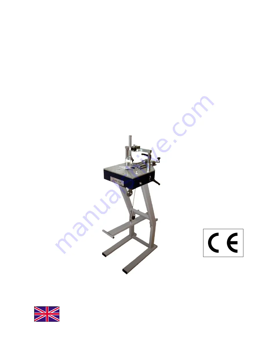
Page 1: ...1 A2M 200 INSTRUCTION HANDBOOK Alfamacchine Via Selva 23 25 47122 Forlì Italy Tel 39 0543 783301 Fax 39 0543 783302 info alfamacchine com www alfamacchine com Minigraf A2M 200 ENGLISH MADE IN ITALY ...

Page 2: ...Y CONTROLS 9 4 7 MACHINE ASSEMBLY 10 4 7 1 KIT Assembly parts list 10 4 7 2 Machine assembly for Front use side 11 4 7 3 Machine assembly for Back use side 12 4 7 1 Wings Assembly 13 4 8 MACHINE ARRANGEMENT 14 4 8 1 V nails magazine loading 14 4 8 2 V nail guide head replacement to change V nails size 14 4 9 ADJUSTMENTS 15 4 9 1 V nails inserting positions adjustment 15 4 9 2 Vertical clamp adjust...

Page 3: ...dbook The warranty decays in case of unauthorized modifications or because of accidental damages or tampering performed by unqualified personnel The warranty also decays in case you use V nails different from the original Alfamacchine ones 1 5 PRE ARRANGEMENTS CHARGED TO THE CUSTOMER It the customer s duty on times agreed with the producer to execute what is indicated in our documentation Things n...

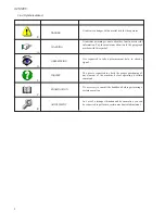
Page 4: ... maximum attention to the paragraph marked with this symbol It is requested to take a measurement data to check a signal The user is requested to check the proper positioning of any element of the machine before operating a certain command It s necessary to consult the handbook before performing a certain operation In case of a strange sitituation and or anomalies you can be requested to perform a...

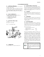
Page 5: ...e The indicated noise levels are emission ones measured in standard conditions of use In case of any machine modification the above mentioned levels could be changed and should be tested on the same machine 2 3 MACHINE STRUCTURE ZAXIS Movement of vertical clamp Fig 2 1 A movement directions 2 4 DIMENSIONS The overall dimensions are reported on table 2 9 A 2 8 NOISE EMISSIONS The machine is designe...

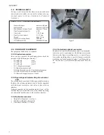
Page 6: ... to ensure the mouldings are locked properly during V nail firing and so on You can have your local machine shop make these for you Figure 1 2 10 1Standard accessories Once you have removed the packaging please check the presence of the following accessories N 1 nail head mm 7 N 1 nail head mm 10 N 1 nail head mm 15 N 1 L shaped pressure pad N 1 Rounding pressure pad N 1AllenWrench 5 mm forV nail ...

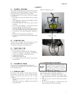
Page 7: ...rts and surrounding zones 3 6 SAFEWORKINGPROCEDURES The other risks related with manual working way are the fingers crushing in the vertical clamp working area It is necessary to follow carefully the following instructions 1 Keep the fingers away from the vertical clamp working area 2 Keep the foot away from the pedal during machine regulation 3 Do not insert any fingres or things between the mech...

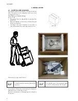
Page 8: ... to lubricate the parts which are not painted According to the type of shipment it is necessary to protect the machine from any jarring impact or stress Figure 4 1A machine handling indications Any damage of the machine caused during its shipment or handling is not covered under warranty Repairs or replacements of damaged parts are charged to the customer Lifting the machine must be performed by 2...

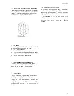
Page 9: ...m receipt of the machine 4 4 PRELIMINARYARRANGEMENTS To install the machine it is necessary to prepare a working area adequate to the machine s dimensions lifting devices chosen and length of mouldings to be worked 4 6 PRELIMINARY CONTROLS The preliminary operations before starting the machine must be executed by a technician appointed by the customer Before setting up the machine it is necessary ...

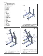
Page 10: ...Knob 21 Step Extension 22 Washer 23 Bolt 24 Left Wing 25 Right Wing 26 n 8 Washer 27 n 8 Screws Pic 1 Pic 2 Pic 3 1 Crew the n 4 rubber feet 2 into the relevants threated holes of the bottom side stand 1 2 Insert the upper side stand 3 into the bottom side one 1 3 Lock the two parts tightening the provided screws 5 and washers 4 4 Aligne the fulcrum side of the pedal 6 between the supports of the ...

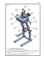
Page 11: ...he user side line up the holes of the machine sides with the stand ones then lock with the screws 13 and washers 12 8 Line up the machine slots to the threated holes of the upper stand and lock by the handles 15 and washers 14 9 Mount the vertical hold down 16 and lock it by the handle 18 and washer 17 10 Hook the main cord 19 to the fork 9 by the provided knob 20 Pic 4 ...

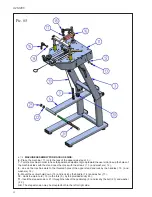
Page 12: ...then lock with the screws 13 and washers 12 8 Line up the machine slots to the threated holes of the upper stand and lock by the handles 15 and washers 14 9 Mount the vertical hold down 16 and lock it by the handle 18 and washer 17 10 Hook the main cord 19 to the fork 9 by the provided knob 20 11 Insert the step extension 21 through the tube of the pedal step 6 and lock by the bolt 23 and washer 2...

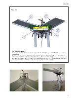
Page 13: ...e up the left wing 24 to the holes of the left side of the machine 11 set the upper face of the wing at the same level of the bench and lock it by the screws 27 and washers 28 14 Line up the right wing 25 to the holes of the right side of the machine 11 set the upper face of the wing at the same level of the bench and lock it by the screws 27 and washers 28 ...

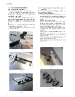
Page 14: ... the magazine Move the clawpusher forward by releasing the control wire see pic 8 Insert the new size V nail guide head to match the V nails to be used see pic 11 Tighten the locking screw of the V nail guide head see pic 9 4 8 MACHINE ARRANGEMENT 4 8 1 V nails magazine loading To load the V nail magazine proceed as follows Move the claw pusher backwards by means of the special control wire locate...

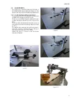
Page 15: ...0 is equipped with a 90 fence The fence can be shifted forward or backward in order to allow the proper positioning of the V nails in the frame The fence limits backward and forward can be set with precision by means of locking clamps A B see pic 12 The operator can easily use the machine to insert V nails with extreme precision between the two 2 mechanical stroke see pic 13 13A Tighten the knob C...

Page 16: ... reached the proper position Be sure that the vertical rod is complrtely in position the pin is in just moving it up an down a little bit Lower the vertical clamp by pressing halfway down on the foot pedal This will verify that the mouldings to be assembled are properly clamped Press all the way down the foot pedal to insert the V nail pic 14 pic 15 pic 16 4 9 5 Working bench tilting adjustment Th...

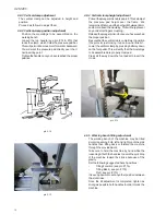
Page 17: ...position of the working bench see pic 18 Once the bench position is set adjust the hook of the cord positioning the cable plug in the proper hole of the pedal fork Tighten the knob to lock the cord at the desired pedal heigh see pic 19 Be sure that once the pedal is completely stepped down the driver blade is completely out to guarantee the complete nail insertion see pic 21 When the foot pedal is...

Page 18: ...r more V nails one upon the other in the same position you must release the pedal halfway and then press it all the way down again to insert the second V nail 4 9 7 Driver Blade heigh adjustment The correct position of the driver blade when it is completely out is when its upper surface is set at the same level of the nail head If the driver blade is too heigh it will sign the wood during the nail...

Page 19: ... and verify the proper positioning and holding of the mouldings to be assembled 5 Press the pedal full down to insert the V nail If you want to insert 2 or more V nails one upon the other in the same position you must release the pedal until half of its stroke and then press again it full down to insert the second V nail and so on 6 Release completely the foot pedal 7 Shift the mouldings and the f...

Page 20: ...dues from the V nail head and from the upper part of the driver blade Always keep the V nail magazine clean without residues Remove any residue from the V nails guide L shaped support Do not use water to clean the machine otherwise metallic parts may oxidise Table 6 4 A Maintenance Description V nail driver blade Replacement every 1 000 000V nails driven Movable parts lubrication Lubricate the dri...

Page 21: ...d the cord to the fork of the head group see pic 26 Remove the wheel of the vertical column group movement to release the cord see pic 27 Place the new cable before to mount back the wheel Hook the upper end of the cord to the head group fork Hook the lower end of the cord to the foot pedal fork at the desired pedal heigh level pic 25 pic 26 pic 27 ...

Page 22: ... during their insertion Wishing to insert several V nails one upon the other in the same point they do not stack properly or tilt during their insertion CAUSE V nails positioned wrong into the V nail magazine magazine is obstructed or damaged Insufficient pressure on the claw pusher The claw head does not match up the v nail height wrong type of v nails The frames clamping is not correct the frame...

Page 23: ...AILSGUIDE 7 3 REQUEST OF ASSISTANCE For any information regarding Use Maintenance Installation etc we remain at your disposal The Customer has to formulate clearly their questions by sending us a fax listing detailed descriptions of the problem For eventual explanations you should use this handbook and the instructions listed in the paragraph 1 2 E_Mail info alfamacchine com FAX 39 0543 783302 via...

Page 24: ......

Page 25: ......

Page 26: ......

Page 27: ......

Page 28: ......

Page 29: ...24 A2M 200 ...

Reviews: