background image


17500 VRANJE, SERBIA 

Radni

č

ka 1, Phone: (+381)17/421-121


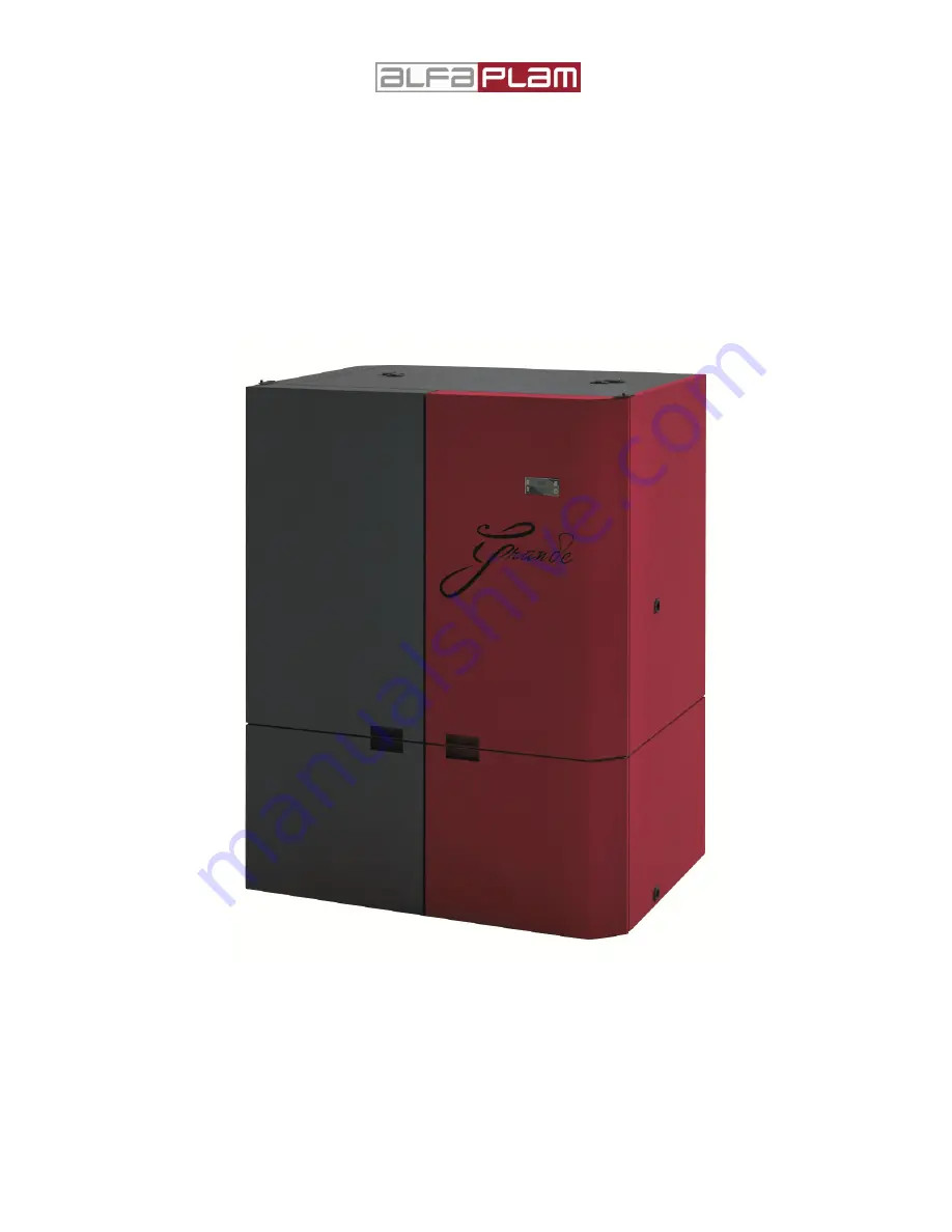
PELLET BOILER


GRANDE 


INSTRUCTION FOR USE, MAINTENANCE AND INSTALLATION 


Version 1.1 / May 2014 


Summary of Contents for GRANDE

Page 1: ...1 17500 VRANJE SERBIA Radnička 1 Phone 381 17 421 121 PELLET BOILER GRANDE INSTRUCTION FOR USE MAINTENANCE AND INSTALLATION Version 1 1 May 2014 ...

Page 2: ... own development on this basis CONTENTS 1 0 CONTENTS OF MANUAL 1 1 UPDATING 2 0 RESPONSIBILITY OF THE PRODUCER 2 1 RESPONSIBILITY OF THE USER 2 2 PREVENTIVE STANDARDS OF MAYOR ACCIDENTS 2 3 TRANSPORT AND HANDLING OF PELLET BOILERS 2 4 RESPONSIBILITY OF THE INSTALLER 3 0 INSTALLING 3 1 SETTING 3 2 FLUE GASES 3 3 INSULATION AND DIAMETERS OF THE OPENING IN THE WALL AND IN THE ROOF 3 4 THE COMBUSTION ...

Page 3: ...the instructions accidents caused by illegal and improper use by the user accident that occurred because of modifications and repairs that are not approved by ALFA PLAM poor maintenance unpredictable situations accidents caused by the use of unoriginal and incompatible spare parts The installer is fully responsible for the installation 2 1 RESPONSIBILITY OF THE USER The user has to meet the follow...

Page 4: ...ments are positive the installation may begin Please follow carefully the instructions given by the manufacturer and the relevant safety and fire standards When the installation is complete it is necessary to carry out the test for at least thirty minutes to check all specified requirements When the installation is complete the installer must provide the buyer with the following Instructions for u...

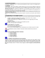
Page 5: ...lue gases many bends inadequate cross section of tubes bottlenecks it is necessary to correct boiler parameters and adjust the work of the chimney to the exhaust system Parameter changes can be made only by the authorized person service personnel If the change of parameters does not produce satisfactory results change the chimney The system of exhaustion of flue gases from the pellet boiler works ...

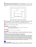
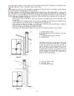
Page 6: ...t the smoke go directly into the chimney provided that its dimensions are 200x200 mm or maximum diameter is 200 mm and that it is equipped with an inspection hole in the event of a larger size chimney it is necessary to install the corrosion proof pipe of maximum diameter of 200 mm The pipe must be properly insulated make sure the connection is properly sealed to the chimney avoid contact with com...

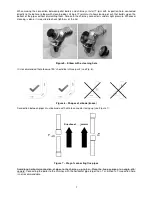
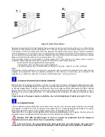
Page 7: ...is required to check tightness of the lid Figure 5 Elbow with a cleaning hole It is recommended that elbows of 90 should be in three parts see Fig 6 Figure 6 Shapes of elbows knees Connection between pipes must be made with a male connector facing up see Figure 7 Figure 7 Way of connecting flue pipes Avoid long horizontal connection of pipes to the chimney up to 3 m Place the flue gas pipe at an a...

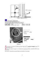
Page 8: ...METER When position of instalation of the boiler is known it is necessary to make a hole opening allowing flue gas flow This position is changed depending on the type of installation diameter of flue gas uptake and the type of the walls or the roof through which it will pass Insulation must be mineral type insulation rock wool of 80 kg m2 nominal density Draft of the chimney depends mainly on the ...

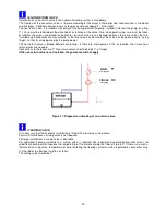
Page 9: ...ACK CABLE PUMP BROWN F BLUE N WHITE CABLE BOILER SUPPLY 220V BROWN F BLUE N Figure 10 Connection of the boiler to the power grid can be done only by a QUALIFIED PERSON based on the attached wiring diagram If the electric cable is damaged it has to be replaced It could be replaced by a QUALIFIED PERSON of the manufacturer ELECTRICAL CONNECTIONS MUST BE EASILY ACCESIBLE ON THE WIRING white cable boi...

Page 10: ... the pump power The non return valve is placed behind each pump If there are more pumps in the installation then more non return valves are needed Connections to the boiler are 1 Non return valves should also be 1 or larger If the non return valve is not installed the guarantee will not apply Figure 11 Diagram for installing of non return valve 3 7 MIXING VALVE It is necessary that the hydraulic i...

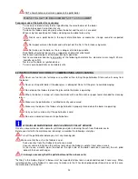
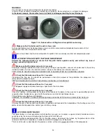
Page 11: ...oiler it is necessary to be sure that the boiler and ash in it are cold THE BOILER SHOULD NOT BE USED IF ANY SAFETY DEVICE IS FAULTY IMPROPERLY REPAIRED OR IS NOT WORKING do not make any repairs of any type for any reason except as permitted or approved by an authorized person always use original spare parts Do not allow the particular part of the boiler to worn out before the same is replaced Tim...

Page 12: ...glass is damaged Do not hit the glass to avoid damaging Do not open the firebox to clean the glass while the boiler is operating When the boiler is turned off clean the boiler with a cotton cloth or paper towel intended for cleaning glass Make sure the pellet boiler is installed correctly and secured Make sure the door of the firebox of a pellet boiler is properly closed when the boiler is operati...

Page 13: ...the flue gas fan should be performed so that after removal of fan protection the plaque on it is removed with a broom or brush SIMPLE PRE SEASON AND POST SEASONAL CLEANING OF THE BOILER Check that the boiler and the ash in it are cold Turn off power supply and make cleaning as specified in the instructions Check that the boiler and the ash in it are cold Check the tightness of the gasket on the do...

Page 14: ...f types and dimensions of the pellets that appear in the market it is important to choose pellets that do not contain impurities which are compact and do not create dust Consult your dealer about the type of pellet the size of which must be 30 mm and diameter 6 mm The proper functioning of the boiler depends on the type and quality of pellets Manufacturer is not in any way responsible for the poor...

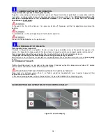
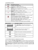
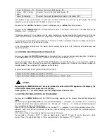
Page 15: ...e changed by pressing and key starts flashing Short press on TURN ON OFF key provides return to the initial display Display Indicator Description Function The upper display shows the status of the boiler the selected menu and the indicator of dosing operation on the timer The lower display shows clock setting values and parameters as well as names of warnings Indicator of the operation of spark pl...

Page 16: ...Screw conveyor stops the inscription STOP FIRE appears on the display fans run at maximum speed to clean the firebox Once the boiler is cooled to the appropriate temperature the boiler shuts down and goes to standby mode The inscription OFF appears on the display WHEN THE BOILER IS IN THE PROCESS STOP OFF Upper LED screen display Displays the OFF Lower LED screen display Displays the current time ...

Page 17: ...D 14 30 P3A 8 30 P3D 10 00 P4A 15 30 P4D 17 30 P5A 16 30 P5D 22 45 P6A 17 30 P6D 21 30 24 6 12 18 P1t 70 P2t 75 P3t 80 P4t 72 P5t 65 P6t 85 DAY1 24 6 12 18 DAY7 T 70 º T 7 5 º T 65 º T 70 º T 72 º Figure 15 Diagram of setting the timer ...

Page 18: ...rature rises properly Burning phase which is usually the working phase The lower display shows the temperature of the flue gas at the outlet of the boiler Combustion phase the lower indicator display displays the temperature of the water in the boiler Combustion phase the lower indicator display displays the temperature of the water in the return line Burning phase the upper indicator display disp...

Page 19: ...iler Otherwise contact the service Reacted safety pressure switch Check the condition of the boiler and if you do not see any problems turn the boiler Otherwise contact the service No signal of flue gases probe Contact the service No signal of firebox temperature Contact the service No flow signals or the fans are not working properly Contact the service It is necessary to clean the boiler and or ...

Page 20: ...re in the chamber 8 Smoke fan speed 9 Voltage of the primary fan 10 Voltage of the smoke fan 11 The percentage of the dosing screw 12 The percentage of the screw conveyor 2 13 The status of the safety thermostat STB YES means OK NO means actuation 14 The status of the safety pressure switch YES means OK NO means the disturbance 15 Status of digital inputs 1 D1 16 Status of digital inputs 2 D2 17 S...

Page 21: ... Does the ignition device lighter work 1 Replace the ignition device 2 Check the output from the electronics relay by voltmeter 3 Check the protection relay ALARM Failed Are there pellets in tank N Fill the tank YE Is the STB switched on protection activated YE N Is the firebox clean Clean the firebox N YE N ...

Page 22: ...more Do you have pellets in the tank N N Fill the tank Is the STB switched on protection activated Does the pellet dosing gear operate 1 Check the possibility of blocking of the screw conveyor 2 Check the STB thermostat 3 Check the mechanics of the snail N YE YE ALARM ...

Page 23: ... Check contamination of the firebox and space underneath 1 Clean the connecting pipe 2 Clean the fan 3 Clean the chimney You need additional sealing Change sealing strip when necessary 1 Check the voltage at the output of the electronics 2 Check round white protective pressure switch 3 Check the STB 4 Check the operation of the safety relay 5 Replace the fan 1 Replace them if they are broken or da...

Page 24: ...tubes between electronics and flow meter OK 1 Replace them if they are broken or damaged 2 If they are clogged or pressed down clean them or set them properly Is it the flow meter canceled Replace the electronics Is the fan FAN1 running 1 Check the voltage at the output of the electronics 2 Check the STB safety thermostat 3 Check operation of the safety relay 4 Replace the fan NO NO NO NO service ...

Page 25: ... 3 Check the heat dissipation from the boiler 1 Replace the STB 2 Check the wiring between the STB and electronics with the diagram Too high temperature of flue gases above 250 C Is exchanger clogged NO Are all turbulators in place 1 Check the exchanger and clean it 2 For automatic cleaning check the cleaning mechanism Replace or reinstall the turbulators NO service man YES YES ALARM STB ALARM GAS...

Page 26: ... connected Connect the sensor to the appropriate place on the electronics Electronics does not recognize the sensor of the temperature of the firebox service man Is sensor connected NO Replace the sensor Connect the sensor to the appropriate place on the electronics YES YES ALARM TC1 ALARM TC2 ...

Page 27: ...nsor Connect the sensor to the appropriate place on the electronics Electronics does not recognize the sensor of the return line service man NO Replace the sensor Connect the sensor to the appropriate place on the electronics Is sensor connected Is sensor connected YES YES ALARM NTC1 ALARM NTC2 ...

Page 28: ...isposal of the boiler can be delegated to a third party that is licensed for such work INDICATION In any case you have to respect the laws of the state in which the pellet boiler is installed WARNING All disassembled parts that should be destroyed must be properly removed remove all electrical components disconnect the battery from the electronics dispose of the battery separate from the electroni...

Page 29: ...sed for commercial purposes if the damage occurred in transportation after the sale of the product if the failure occurred due to improper assembling improper maintenance or mechanical damage by the customer if the failure was caused by too high or too low voltage and force majeure We can also remove product failures after the warranty period with original spare parts for which we give warranty on...

Page 30: ...rent during highest power consumption 1 80 A Frequency 50 Hz Highest power consumption during operation of the boiler 78 5 W Lowes power consumption during operation of the boiler 19 W Highest power consumption at turning the boiler 280 5 W Degree of safety IP 20 Heating appliance is running with using a fan YES Heating appliance is working with under pressure at flue gas outlet YES Heating applia...

Page 31: ...31 16 0 DIMENSIONS OF BOILER GRANDE Figure 17 ...

Page 32: ...pe connection Ø80 mm 3 Distribution line 4 Expansion vessel 5 Safety valve 6 Radiator valve 7 Radiator 8 Air release valve 9 Circulation pump 10 Return line 11 Faucet for filling and emptying 12 Pressure gauge 13 The drain pipe from the safety valve 14 Boiler for sanitary water 15 Automatic air vent pot ...

Reviews: