background image

IF Distributors

75-90-xxxx

Distributor

Summary of Contents for Interflex 75-90 Series

Page 1: ...IF Distributors 75 90 xxxx Distributor...

Page 2: ...l strip 11 3 Installing the distributor 13 3 1 Installation site 13 3 2 Fastening the distributor 13 4 Connecting the power supply 14 4 1 Connecting the distributor 7590 xx12 to power supply 230 V 14...

Page 3: ...ributors 06 22 3 7 2 Distributors 75 90 0001 and 75 90 xx12 19 7 3 Distributor 75 90 1x11 20 7 4 Distributor 75 90 2xx1 21 8 Disposal 21 9 Declarations of conformity 22 9 1 EU Declaration of Conformit...

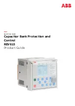
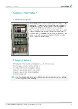
Page 4: ...system if the housing is opened without permission The distributors are available in versions with or without their own power supply with or without an integrated IF 4072 controller and 0 4 or 8 I O c...

Page 5: ...o electric shock People can be seriously hurt or killed through physical contact with live parts e g 230 V u Make sure that you cannot touch live lines during installation u Switch off the power suppl...

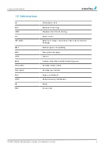
Page 6: ...g DC Direct Current DIP switch Switch in IC design connections in two rows Dual In line Package EMC Electromagnetic Compatibility ESD Electrostatic discharge GND Ground IEEE Institute of Electrical an...

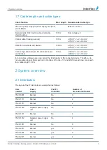
Page 7: ...terminal 100 m J Y St Y 4 x 2 x 0 6 mm2 J Y St Y 4 x 2 x 0 8 mm2 In long cables voltage losses can impair the functionality of the connected device Therefore do not use cables longer than specified i...

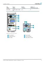
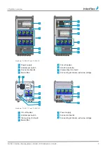
Page 8: ...er Power supply IF 4072 Controller Number of I O controller boards 75 90 2812 Separate power supply unit yes 8 2 3 2 3 4 6 1 1 5 5 Distributors75 90 2401 and 75 90 0001 1 Circuit breaker 2 Power suppl...

Page 9: ...reaker 3 Anti tamper switch 4 IF 4072 controller 5 Connector boards 6 Clamp strap for shield 7 Mains filter 8 Connecting terminals extra low voltage 3 5 6 5 4 4 6 3 1 2 7 Distributor 75 90 1111 and 75...

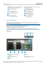
Page 10: ...ing figure shows the layout of half a connector board 1 2 3 4 1 Connector board 2 I O controller board 3 DIP switch for addressing the I O controller board 4 Fuse protection Connections GND IN2 GND IN...

Page 11: ...nection 2 13 I O controller board 2 monitoring of door opener 14 I O controller board 2 Inputs IN 1 and 2 2 3 Terminal strip Distributors of the series 75 90 2401 are connected via I O controller boar...

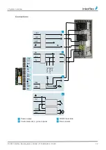
Page 12: ...ysteme GmbH IF Distributors 06 22 12 Connections BAT AC AC IN2 GND IN1 Tx Tx SH REL REL AC AC BAT 1 SH Tx Tx SH Tx Rx Tx Rx 2 REL REL 3 1 IN1 GND 4 IN2 PE PE 1 Power supply 2 RS485 bus cable 3 Control...

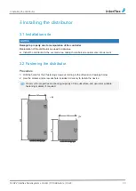
Page 13: ...data loss u Install the distributor in the secured area taking the technical requirements into account 3 2 Fastening the distributor Procedure 1 Drill the holes for the 4 fastening screws according to...

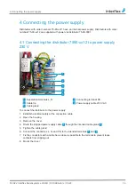
Page 14: ...1 Separation terminals L N 2 Connecting terminal PE 3 Cable tie 4 Power supply cable 230 V AC 5 Cable gland To connect the distributor to the power supply 1 Establish electrical safety at the connect...

Page 15: ...tra low voltage supply of the distributor must be connected as shown in the figure Observe the notes under Cable lengths and cable types 7 1 2 4 3 5 6 8 7 75 90 0001 75 90 xx12 1 Connecting terminal P...

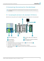
Page 16: ...terminal board via the connector board VCC COM COM Tx Tx V V BE 4 2 6 5 3 1 1 Cable shield drain wire 2 Connection cable to terminal terminal board 3 Terminal board 4 Clamp strap for shield at the dis...

Page 17: ...x Tx V V BE 4 2 5 3 1 1 Cable shield drain wire 2 Connection cable to terminal terminal board 3 Terminal board 4 Clamp strap for shield at the distributor 5 I O controller board To connect the termina...

Page 18: ...the higher ranking system through the divisible cable gland 5 to the controller 2 Insert the plug of the network cable in the socket 2 at the controller 3 Strip the network cable and secure it with th...

Page 19: ...5 90 0001 The distributor 75 90 0001 may only be used for supplying power to one of the distributors 75 90 xx12 The connection cable must not be longer than 3 m Nominal voltage 230 V AC 10 0 325 A 50...

Page 20: ...90 1x11 75 90 1111 75 90 1211 Nominal voltage 230 VAC 10 0 12 A 50 Hz Power for door openers 24 V DC max 0 2 A Power for terminals 20 V AC 0 33 A Power consumption 30 VA Power circuit breaker Circuit...

Page 21: ...24 V DC max 2 15 A Power for terminals 20 V AC 0 53 A 20 V AC 0 86 A 20 V AC 0 86 A Power consumption 30 VA 45 VA 64 VA Power circuit breaker Circuit breaker 230 VAC 6 A Fuse 2 x 0 5 AT per I O contro...

Page 22: ...gram packages that are subject to Open Source License Terms The license information and the links to the OpenSource projects are available for download on the product in the directory home fieldservic...

Reviews: