background image

Installation Instructions

Original Instructions

PowerFlex 755 IP00, NEMA/UL Open Type Drive Frames 8…10

Catalog Numbers 200…1500 kW (250…2000 Hp)

This document provides instructions for the installation of an IP00, Open Type PowerFlex® 755 drive (Frames 8…10) in 
a user supplied enclosure.

The information provided in this publication supplements the PowerFlex 750-Series AC Drives Installation Instructions, 
publication 

750-IN001

, and is intended for qualified drive service personnel only.

Topic

Page

Summary of Changes

2

General Precautions

2

Certifications

3

Overview

4

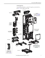
Installation Overview

6

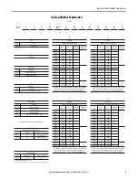
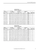
AC Input Drives

8

Common DC Input Drives

12

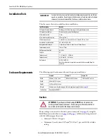
Installation Tools

16

Enclosure Requirements

16

CE Conformity

23

Horizontal Mounting Guidelines – Single Drive Unit Only

26

Dimensions

28

Lifting

36

Drive Installation

38

Selecting/Verifying Control Transformer Voltage

41

Installing the Control Pod in the Drive

42

Power Wiring

45

Kit Installation Guidelines

49

Cable Routing

58

I/O Wiring

59

Fuse and Circuit Breaker Ratings

67

Additional Resources

76

Summary of Contents for PowerFlex 755 IP00

Page 1: ...001 and is intended for qualified drive service personnel only Topic Page Summary of Changes 2 General Precautions 2 Certifications 3 Overview 4 Installation Overview 6 AC Input Drives 8 Common DC Inp...

Page 2: ...that all power to the drive has been removed before proceeding In addition before servicing verify that the voltage on the bus capacitors has discharged Measure the DC bus voltageonFrame8drivesattheD...

Page 3: ...onsarerequiredwheninstalling testing servicing or repairing this assembly Component damage may result if ESD control procedures are not followed If you are not familiar with static control procedures...

Page 4: ...d purchase necessary wire and cabling pages 45 59 3 Prepare the Enclosure Create ventilation openings mount door fans pages 17 21 Provisions for accessories HIM cradle etc see 750 TD001 Fabricate and...

Page 5: ...5 1100 2 D740 1420 1250 2 D545 1525 1350 3 10 D740 2070 1750 3 To achieve the extended ratings listed for Frames 9 and 10 the base Frame 8 drive must be paralleled 2 or 3 times Refer to the Drive Rati...

Page 6: ...Input Termination Kit Sub Panel for reference only IP00 Frame 8 Drive Assembly Inverter Converter Mounting Kit Inverter DC Bus Termination Kit Optional for a Frame 8 equivalent Use only if the applica...

Page 7: ...tion 750 IN015 for remote mounting information IP00Frame8CommonDC Input Drive Assembly w Precharge Sub Panel for reference only Control Transformer Overload Protection required for Common DC Input dri...

Page 8: ...0G11TC750 2 9 1576 1600 1760 900 1457 1480 1628 2220 850 1157 1175 1763 2220 710 360 440 20G11TC770 2 9 1689 1715 1887 1000 1566 1590 1749 2385 900 1305 1325 1988 2385 710 360 440 20G11TC567 3 10 2294...

Page 9: ...0 900 540 660 20G11TE510 2 9 1151 1220 1342 1200 1048 1110 1221 1665 1100 868 920 1380 1665 1000 540 660 20G11TE395 3 10 1444 1530 1683 1500 1350 1430 1573 2145 1400 1123 1190 1785 2145 1250 540 660 2...

Page 10: ...ncluding Main Control Board and Fiber Interface Board Mount in the left most bay of the drive or remotely see below 4 6 Control Pod Remote Harness 20 750 RPD1 F8 1 20 750 RPD1 F8 9 2 20 750 RPD1 F8 9...

Page 11: ...ckwell Automation Publication 750 IN020D EN P May 2017 11 PowerFlex 755 IP00 NEMA UL Open Type Drive PE PE PE PE Power 755 Frame8 Frame9 Frame10 1 2 4 6 3 5 4 1 2 4 6 3 5 4 1 2 4 6 3 5 4 7 8 11 9 12 1...

Page 12: ...0 2 9 1841 1600 1760 900 1703 1480 1628 2220 850 1352 1175 1763 2220 710 486 594 20G14TC770 2 9 1974 1715 1887 1000 1830 1590 1749 2385 900 1525 1325 1988 2385 710 486 594 20G14TC567 3 10 2681 2330 25...

Page 13: ...E510 2 9 1345 1220 1342 1200 1224 1110 1221 1665 1100 1015 920 1380 1665 1000 729 891 20G14TE395 3 10 1687 1530 1683 1500 1577 1430 1573 2145 1400 1312 1190 1785 2145 1250 729 891 20G14TE510 3 10 Ligh...

Page 14: ...d including Main Control Board and Fiber Interface Board Mount in the left most bay of the drive or remotely see below 2 4 Control POD Remote Harness 20 750 RPD1 F8 1 20 750 RPD1 F8 7 2 20 750 RPD1 F8...

Page 15: ...Rockwell Automation Publication 750 IN020D EN P May 2017 15 PowerFlex 755 IP00 NEMA UL Open Type Drive Power 755 Frame8 Frame9 Frame10 Not Shown 1 3 4 3 5 2 1 4 3 5 2 3 1 4 3 5 2 3 6 7 8 9 10 11 12...

Page 16: ...oor covering seat and ground connections ESD protectiveclothing Wrist wrap shoes overall clothing coat Allen socket wrench 5 mm Allen socket wrench extension 254 mm 10 in Flat nose screw driver 5 mm 0...

Page 17: ...e enclosure cooling requirements must be supplied as specified When mounting the drive vertically the enclosure door must be provided with openings for air intake as shown To achieve sufficient coolin...

Page 18: ...with optional hood and inlet filter 1 2 3 4 IMPORTANT For vertical mounting applications a duct section must be fabricated to fit between the gasket on the drive and the inside of the enclosure door...

Page 19: ...top mounting bracket and should be installed before the drive unit is rolled in User supplied ducting is mounted toenclosure top and matches up withtheductingkit UseM6screws of suitablelengthtoattachd...

Page 20: ...in pitch 2 position 12A 250V 24 12 AWG To gain access to the Control Transformer see the PowerFlex 755 AC Drives Hardware Service Manual publication 750 TG001 To select or verify transformer primary v...

Page 21: ...he drive TB2 1 2 3 4 TB2 1 2 3 4 5 6 Flat 0 5 N m 4 5 lb in Flat 0 5 N m 4 5 lb in AC Input Drive Common DC Input Drive Drive Terminal Name Description Strip Length AC Input Drive 1 Shunt Trip Com Do...

Page 22: ...opper Common DC input kits are not compliant with EN 61800 5 1 Figure 7 Drive Grounding PE PE PE PE PE PE PE Grounding Location for Bottom Cable Entry Inverter Termination Kit Grounding Location for T...

Page 23: ...e drives must satisfy installation requirements related to both EN 61800 5 1 and EN 61800 3 provided in this document PowerFlex 750 Series AC Drives comply with the EMC requirements of EN 61800 3 when...

Page 24: ...ical shock PowerFlex 750 Series drives produce leakage current in the protective earthing conductor which exceeds 3 5 mA AC and or 10 mA DC The minimum size of the protective earthing grounding conduc...

Page 25: ...mentary mitigation Consult factory Compliance possible with supplementary mitigation Consult factory 30 m motor cable limit 1 with output core 2 30 m motor cable limit 1 with output core 2 Frame 9 AC...

Page 26: ...ge Figure 8 Open Style Drive Horizontal Installation Figure 9 Bottom Inlet Ducting Kit Dimensions Bottom Inlet Duct Kit Converter AC Input Field Termination Kit Inverter ACOutput Field Termination Kit...

Page 27: ...Hp 480 470 0 460 479 400 Hp 480 362 0 460 369 250 Hp D617 480 567 0 460 577 450 Hp 480 567 0 460 577 450 Hp 480 387 0 460 394 300 Hp D710 480 610 0 460 622 500 Hp 480 610 0 460 622 500 Hp 480 435 0 46...

Page 28: ...astner 10 Places Captive Duct Interface Hardware 4 Places 1513 6 59 59 1654 6 65 14 1718 6 67 66 1846 6 72 70 1922 6 75 69 2012 4 79 23 1983 8 78 10 2063 7 81 25 1248 7 49 16 W T3 V T2 U T1 DC DC T L3...

Page 29: ...nterface Hardware 4 Places 1513 6 59 59 185 9 7 32 316 4 12 46 424 9 16 73 12 7 0 50 474 0 18 66 486 6 19 16 0 0 0 00 0 0 0 00 288 4 11 36 0 4 0 02 13 0 0 51 0 3 0 01 375 9 14 80 474 3 18 67 487 0 19...

Page 30: ...side of Cabinet Post 54 4 2 14 Max Backset 93 9 3 70 403 9 15 90 0 0 0 00 0 0 0 00 119 2 4 69 17 0 0 67 236 0 9 29 466 0 18 35 1619 8 63 77 1978 8 77 91 1228 3 48 36 1728 6 68 05 1600 6 63 02 1472 6 5...

Page 31: ...00 1228 3 48 36 1100 0 43 31 953 1 37 52 788 0 31 02 623 0 24 53 0 0 0 00 119 2 4 69 236 0 9 29 466 0 18 35 1619 8 63 77 1978 8 77 91 420 5 16 56 93 9 3 70 309 9 12 20 2035 2 80 13 2111 8 83 14 777 9...

Page 32: ...0 0 0 00 1228 3 48 36 1728 6 68 05 1600 6 63 02 1472 6 57 98 1100 0 43 31 953 1 37 52 788 0 31 02 623 0 24 53 420 5 16 56 777 9 30 63 2035 2 80 13 2065 6 81 32 2111 8 83 14 2145 0 84 45 0 0 0 00 119 2...

Page 33: ...0 1228 3 48 36 1100 0 43 31 953 1 37 52 788 0 31 02 623 0 24 53 1577 8 62 12 777 9 30 63 157 0 6 18 309 9 12 20 420 5 16 56 0 0 0 00 119 2 4 69 236 2 9 30 466 0 18 35 1666 5 53 80 1978 8 77 91 2035 2...

Page 34: ...68 05 1600 6 63 02 1472 6 57 98 1100 0 43 31 953 1 37 52 788 0 31 02 623 0 24 53 2035 2 80 13 2065 6 81 32 2111 8 83 14 2145 0 84 45 0 0 0 00 119 2 4 69 236 2 9 30 466 0 18 35 1666 5 53 80 1978 8 77 9...

Page 35: ...3 48 36 1100 0 43 31 953 1 37 52 788 0 31 02 623 0 24 53 2377 9 93 62 1577 8 62 12 777 9 30 63 0 0 0 00 119 2 4 69 236 2 9 30 466 0 18 35 1666 5 53 80 1978 8 77 91 157 0 6 18 309 9 12 20 420 5 16 56...

Page 36: ...ttachment before lifting drive or enclosure Do not allow any part of the drive enclosure or lifting mechanism to make contact with electrically charged conductors or components Do not subject the driv...

Page 37: ...e Moving the Drive Assembly to a Vertical Position IMPORTANT Remove shipping brackets prior to installation IMPORTANT When approaching the full upright vertical position be aware of the wheels at the...

Page 38: ...page 14 Recommended placement and dimensions for the kit are provided on page 39 or page 40 Brackets are supplied on the drive assembly for attaching the Mounting kit components The Mounting kit is r...

Page 39: ...6 3 959 192 42 7 575 308 17 12 133 422 42 16 631 771 66 30 380 909 16 35 794 941 66 37 073 1271 66 50 065 1311 66 51 640 1462 27 57 570 1576 27 62 058 1688 38 66 472 1821 28 71 704 1935 28 76 192 160...

Page 40: ...0 56 3 959 192 42 7 575 308 17 12 133 422 42 16 631 771 66 30 380 909 16 35 794 941 66 37 073 1271 66 50 065 1311 66 51 640 1208 77 47 590 1322 77 52 078 1688 38 66 472 1821 28 71 704 1935 28 76 192 1...

Page 41: ...es the single phase 240V internal control voltage power for the drive blower and the enclosure fans If the line voltage is different than the voltage class specified on the drive nameplate it may be n...

Page 42: ...rder the Remote Mount kit catalog number 20 750 RPD1 F8 1 Loosen but do not remove the bottom two M4 x 12 mm slotted hexalobular screws that secure the control pod cover to the assembly 2 Remove the t...

Page 43: ...harness into terminal P14 on the Fiber Interface Board 6 Connect one end the fiber optic cable to P1 INV1 on the Fiber Interface Board IMPORTANT Minimum inside bend radius for fiber optic cable is 50...

Page 44: ...Control Pod Cover OptionalExternalPowerSupply An external power source supplies control power to the drive when the drive is not energized Connect an optional external 24V power supply to P13 using th...

Page 45: ...d cause large potential differences between the drive or line up grounds For installations within an enclosure a single safety ground point or ground bus bar connected directly to building steel shoul...

Page 46: ...nted in the Wiring and Grounding Guidelines for Pulse Width Modulated PWM AC Drives publication DRIVES IN001 must be followed when using non inverter grade motors to avoid premature motor failures Typ...

Page 47: ...e pages 49 57 for kit installation guidelines and page 39 or page 40 for recommended mounting locations and dimensions ATTENTION To guard against drive damage Do Not connect power wires directly to th...

Page 48: ...AC Output 9 20 750 BUS3 F9 1664A AC 1600A AC 1090A AC 1060A AC Inverter DC Bus 400 480V 9 20 750 BUS4 F9 1914A DC 1764A DC N A 1 N A 1 DC Input for Common Bus Precharge 9 20 750 BUS5 F9 1914A DC 1764A...

Page 49: ...50 BUS2 F8 8 Inverter AC Output Field Termination 20 750 BUS3 F8 PE 73 50 2 894 PE x 12 Movable L bracket Side Detail Ground Bond Strap seepage22forhardware and torque requirements M10 37 9 N m 336 lb...

Page 50: ...0 750 BUS4 F8 8 DC Input for Common Bus PrechargeField Termination 20 750 BUS5 F8 Frame Kit Steps 73 50 2 894 x 8 Movable L bracket Side Detail Ground Bond Location see page 22 for hardware and torque...

Page 51: ...20D EN P May 2017 51 PowerFlex 755 IP00 NEMA UL Open Type Drive 8 DC Input for Common Bus PrechargeField Termination continued Frame Kit Steps 4 3 M10 37 9 N m 336 lb in Ground Bond Location see page...

Page 52: ...Open Type Drive 8 10 Mounting Floor Rail 20 750 MNT3 F8 Frame Kit Steps x2 x2 x2 Rittal Style Enclosure Hoffman Style Enclosure Note Discard unused spacers TheFloor RailKitissuppliedwithtwosetsofspac...

Page 53: ...ion Publication 750 IN020D EN P May 2017 53 PowerFlex 755 IP00 NEMA UL Open Type Drive 9 Converter AC Input Field Termination 20 750 BUS2 F9 Frame Kit Steps 73 50 2 894 M10 37 9 N m 336 lb in T40 M8 9...

Page 54: ...Inverter DC Bus Field Termination 20 750 BUS4 F9 400 480V 20 750 BUS6 F9 600 690V Frame Kit Steps 73 50 2 894 M10 37 9 N m 336 lb in T40 M8 9 0 N m 80 lb in 73 50 2 894 M10 37 9 N m 336 lb in T40 M8...

Page 55: ...5 PowerFlex 755 IP00 NEMA UL Open Type Drive 9 DC Input for Common Bus PrechargeField Termination 20 750 BUS5 F9 Frame Kit Steps 73 50 2 894 M10 37 9 N m 336 lb in T40 M8 9 0 N m 80 lb in Ground Bond...

Page 56: ...x 755 IP00 NEMA UL Open Type Drive 10 Converter AC Input Field Termination 20 750 BUS2 F10 10 Inverter AC Output Field Termination 20 750 BUS3 F10 Frame Kit Steps 73 50 2 894 M10 37 9 N m 336 lb in T4...

Page 57: ...for Common Bus PrechargeField Termination 20 750 BUS5 F10 Frame Kit Steps 73 50 2 894 M10 37 9 N m 336 lb in T40 M8 9 0 N m 80 lb in Ground Bond Location see page 22 for hardware and torque requiremen...

Page 58: ...Description 1 I O signal cable shield termination points Use M4 screws and ring terminals provided to tie together and terminate drain wires and shields 2 Groundshieldwirestooutersheetmetalbucket Str...

Page 59: ...e and drift in sensitive input circuits can cause unpredictable changes in motor speed and direction Use speed command parameters to help reduce input source sensitivity Type Wire Type s Description M...

Page 60: ...RealTimeClock setting in the event power to the drive is lost or cycled 4 DPI Port 2 Cable connection for handheld and remote HIM options 5 ENABLE Jumper Hardware enable jumper Removed when a hardware...

Page 61: ...s 1 Access the Control Pod 2 Locate and remove the ENABLE Jumper on the Main Control Board see page 60 FiberInterfaceBoard Name Wire Size Range Torque Strip Length Maximum Minimum Maximum Recommended...

Page 62: ...olt power Powers control circuits when main power is removed 3 P14 Connections for internal drive supplied 24 volt power Connection is factory wired and must not be modified by the user Powers control...

Page 63: ...ipment damage exists if an option module is installed or removed while the drive is powered To avoid damaging the drive verify that the voltage on the bus capacitors has discharged completely and all...

Page 64: ...plied to the I O Module digital inputs See the I O Module catalog number to determine the voltage rating 20 750 2262C 2R is rated 24 Volts DC 20 750 2262C 1R2T is rated 24 Volts DC 20 750 2262D 2R is...

Page 65: ...70 on Port X Ai1 Analog Input 1 24VC 24 Volt Common 1 1 Not present on 120V versions Drive supplied logic input power 200 mA max per I O module 600 mA max per drive 24V 24 Volt DC 1 Di C Digital Input...

Page 66: ...ay Normally Open contact output 240V AC 24V DC 2 A max General Purpose Inductive Resistive Relay Normally Closed contact output 240V AC 24V DC 2 A max Resistive Only 10 100 101 105 106 on Port X R0C R...

Page 67: ...do not match the tables provided the closest fuse rating that exceeds the drive rating should be chosen IEC BS88 British Standard Parts 1 2 1 EN60269 1 Parts 1 2 type gG or equivalent should be used U...

Page 68: ...12 Light 20G11TC567 1 673 604 1100 800 400 1300 800 400 1800 1800 800 1600 650 Normal 20G11TC650 1 715 975 640 1100 850 425 1400 850 425 1900 1900 800 1600 642 Heavy 20G11TC770 1 963 1155 634 1100 800...

Page 69: ...a 200 kW motor or in Light Duty mode on a 315 kW motor The drive can be programmed for each mode Wiring and fuses can be sized based on the programmed mode For any given drive catalog number Normal Du...

Page 70: ...325 1600 1600 650 1600 500 Hp 8 590 Light 20G11TD54 1 649 557 1100 700 1300 700 1700 1700 700 1600 617 Normal 20G11TD617 1 679 926 582 1100 750 325 1300 750 325 1800 1800 800 1600 617 Heavy 20G11TD740...

Page 71: ...y mode on a 300 Hp motor or in Light Duty mode on a 400 Hp motor The drive can be programmed for each mode Wiring and fuses can be sized based on the programmed mode For any given drive catalog number...

Page 72: ...1200 1200 500 1000 395 Heavy 20G11TE460 1 593 711 373 900 500 250 900 500 250 1200 1200 500 1000 450 Hp 8 435 Light 20G11TE395 1 479 411 900 550 275 1000 550 275 1300 1300 550 1000 435 Normal 20G11TE4...

Page 73: ...uty mode on a 500 Hp motor The drive can be programmed for each mode Wiring and fuses can be sized based on the programmed mode For any given drive catalog number Normal Duty mode provides higher cont...

Page 74: ...675 353 900 450 225 800 450 225 1100 1100 450 1000 400 kW 8 410 Light 20G11TF370 1 451 386 900 500 250 900 500 250 1200 1200 500 1000 415 Normal 20G11TF415 1 457 639 377 900 500 250 900 500 250 1200...

Page 75: ...grammed for each mode Wiring and fuses can be sized based on the programmed mode For any given drive catalog number Normal Duty mode provides higher continuous current but smaller overload current wit...

Page 76: ...ives PowerFlex 750 Series AC Drives Technical Data publication750 TD001 Includesinformationaboutcertifications specifications anddesignconsiderationsforthe 750 Series AC Drives Also includes informati...

Page 77: ...Rockwell Automation Publication 750 IN020D EN P May 2017 77 PowerFlex 755 IP00 NEMA UL Open Type Drive Notes...

Page 78: ...the How Are We Doing form at http literature rockwellautomation com idc groups literature documents du ra du002_ en e pdf Technical Support Center Knowledgebase Articles How to Videos FAQs Chat User...

Reviews: