


Installation/Operation
www.comlaundry.com
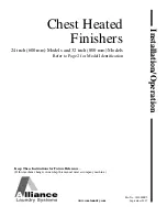
Chest Heated
Finishers
24 inch (600 mm) Models and 32 inch (800 mm) Models
Refer to Page 2 for Model Identification
Part No. 1800000R2
September 2007
Keep These Instructions for Future Reference.
(If this machine changes ownership, this manual must accompany machine.)
Summary of Contents for UL24A118
Page 2: ......