background image


M

M

u

u

l

l

t

t

i

i

P

P

r

r

e

e

p

p


S

S

y

y

s

s

t

t

e

e

m

m


115 V AC & 230 V AC & CE 


Operation Manual 


2376 E. Pacifica Place, Rancho Dominguez, CA 90220 * 310-635-2466 

www.alliedhightech.com


03/13, Version 7.6 

Summary of Contents for MultiPrep System 15-2000-GI

Page 1: ...M Mu ul lt ti iP Pr re ep p S Sy ys st te em m 115 V AC 230 V AC CE Operation Manual 2376 E Pacifica Place Rancho Dominguez CA 90220 310 635 2466 www alliedhightech com 03 13 Version 7 6 ...

Page 2: ...3 18 Vertical Movement Positioning 13 Fixture Attachment 14 Rotation 15 Oscillation 16 Angular Adjustments 17 Sample Load 18 MultiPrep System Alignment 18 23 Theory 18 Step 1 Verification of Platen Run Out 19 20 Step 2 Perpendicular Alignment of Spindle to Platen 21 22 Step 3 Alignment of Micro Hub Assembly to Platen 22 23 Explanation of Digital Indicators 24 25 Specific Material Removal 25 26 Fix...

Page 3: ...ator must ensure pieces being ground polished are held securely 6 The operator should not wear loose clothing ties jewelry or other items that may get entangled in the machine during operation Safety Labels Electrical This label is located on the rear of the machine and indicates where the power cord is connected Remove the power cord when changing fuses or when performing any service Hand Entangl...

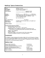
Page 4: ...shed If operated in humid climates steel components such as bearing and spindle components can fail prematurely Altitude None established Pollution Degree 2 Mains Supply Voltage Not to exceed 10 of the nominal voltage Transient overvoltages according to overvoltage category II Frequency Note The MultiPrep System is designed to operate at either 50 Hz or 60 Hz frequency however the unit is electron...

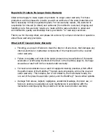
Page 5: ...nt so customer repairs with no charge parts from Allied are often the quickest and easiest way to return a product to active service If you wish to return a product to Allied for warranty repair you must first obtain a Return Equipment Authorization number REA An REA may be obtained from your Product Application Specialist or from a member of our Technical Services staff Please ensure that your RE...

Page 6: ...result of failure to clean the drain or drain screen that damages any internal electrical or mechanical components of the machine will not be covered under warranty Failure to regulate and control the water pressure may cause failure of the water solenoids or overflowing the limits of the drain in the machine page 8 Damage caused as a result will not be covered under warranty Corrosion and oxidiza...

Page 7: ...r left corner will illuminate as will the LEDs in the timer and RPM display windows Using the keypad enter an RPM value in the range between 5 and 350 in 5 RPM increments and press ENTER followed by the green RUN button The platen will rotate in the direction selected The direction of the platen is selected using the buttons labeled with clockwise and counterclockwise circular arrows An illuminate...

Page 8: ...press the outer collar of the fitting in and pull the tubing out Note Turn the water off at the source before removing the water tubing Drain With the hose clamp on the drainage hose position the hose onto the coupling at the rear service panel Figure 1 Tighten the hose clamp so the hose does not slip from the coupling Use the 90 degree elbow fitting to direct the drain hose if the tubing does not...

Page 9: ...n ENTER and allow it to run for another 10 seconds With the machine running at 350 RPM press and hold the ENTER button until two quick beeps followed by four additional beeps are heard then release the button This will begin calibration by storing the accurate speeds into memory The time of the calibration process will vary but it will usually be complete after about 25 to 30 minutes When the cali...

Page 10: ...tween the platen and the platen base clean and dry so the platen run out remains within specifications Excessive water and polishing suspension buildup will adversely affect the run out Splash Ring Each machine comes with one 1 splash ring that is designed to collect and direct the water and polishing liquids into the drain bowl To maintain cleanliness avoid contamination and ensure safety it is s...

Page 11: ...the platen is activated Should the machine be stopped during operation the timer will stop counting it will resume when the RUN button is pressed again Set the timer by pressing the TIMER button the LED will illuminate Enter the desired time using the keypad and press ENTER If during entry a mistake is made press the C clear button and re enter the correct time followed by pressing ENTER When the ...

Page 12: ...y again makes contact with the arm a mechanical stop During downward travel the spindle maintains rigid precise geometric orientation of the sample relative to the abrasive plane Micrometer heads fitted to the micro hub assembly at the bottom of the rotating spindle provide adjustment for sample tilt to meet various angular requirements The front digital indicator is dynamic moving featuring 1 µm ...

Page 13: ...the spindle pulley makes contact with the arm The rear digital indicator displays movement of the arm position in one micron increments in either or values depending on the selection made on the indicator Spindle Riser The spindle riser also called the cam riser which is located on the left side of the arm Figure 6 is used to raise the spindle without changing the vertical position of the arm It s...

Page 14: ... and fixture fit without contacting the platen abrasive To attach a fixture slide it onto the plate until it makes full contact with the reference edge Make sure it has engaged the cam lock plunger Rotate the cam lock lever clockwise until tight Mounting the sample onto the fixture is usually done with hot mounting wax double sided adhesive tape glue or set screws as required by the type of sample...

Page 15: ... selected press the FULL key again and the LED will turn green The selected speed will remain the default speed until it is reprogrammed 2 Limit Rotation Limit rotation allows the sample to be rotated swiveled pivoted in an alternating direction between two points defined by the position of two magnets The speed setting is adjusted as described above except by pressing the LIMIT button rather than...

Page 16: ... OSC key again and the LED will turn green The selected speed will remain the default speed until it is reprogrammed 2 Position The oscillation position is the area over the platen where the sample will sweep and is defined by the drive linkage length Set the oscillation position after setting the sweep range It can be adjusted after loosening the position thumbscrew Figure 10 The longer the linka...

Page 17: ... and the left front micrometer Radial Left to right adjustments are made using the micrometer located at the right rear The left to right adjustment is also known as Roll Rotate the micrometer clockwise to lower the right side and rotate it counterclockwise to raise the right side Axial Front to back adjustments are made using the micrometer located at the left front The front to back adjustment i...

Page 18: ... of this alignment depends upon how much use the MultiPrep System sees in a given time period Alignment is a process that takes only minutes to accomplish and it is highly recommended prior to starting any sample preparation procedure The MultiPrep head and base are machined to very tight tolerances The accuracy of alignment is dependent upon the cleanliness of the platen and platen base It is ver...

Page 19: ...tating the threaded ring collar 5 Position the dial indicator tip at an angle just below the adapter body Figure 16 6 Attach the adapter plate indicator to the MultiPrep using the cam lock and then lower the cam riser Rotate the indicator bezel so 100 is at the 6 o clock position Figure 17 7 Adjust the oscillator linkage to position the dial indicator tip approximately one 1 inch from the edge of ...

Page 20: ...t illustration When platens not originally shipped with the system are used it is recommended that they be checked marked and matched for minimal run out On the underside of the platen there are four 4 small holes into which the drive pins of the platen base fit Rotate the platen on center until the drive pins engage and the platen rests on the edge of the platen base Check the run out at each of ...

Page 21: ...ns 4 µm alignment is necessary Perpendicular alignment is accomplished by adjusting the screws on the leveling plate Figure 21 The first adjustment involves positioning the dial indicator at the 3 and 9 o clock positions and adjusting the screws on the right side of the leveling plate until the readings are equal The second adjustment involves positioning the indicator at the 6 and 12 o clock posi...

Page 22: ... the needle is less than 2 divisions 4 µm Step 3 Alignment of Micro Hub Assembly to Platen The micrometer heads on the micro hub assembly are used to adjust tilt a sample by changing its angle relative to the platen Changing its angle should be performed when there are variations caused by mounting wax uneven encapsulation of potted and packaged samples tape etc Alignment through adjustment of the...

Page 23: ...Activate full sample rotation and stop it when the indicator tip is directly beneath the first micrometer head Figure 25 7 Adjust the micrometer head to return the dial indicator needle back to 0 in the opposite rotational direction of its movement during Step 6 For example if the indicator moved clockwise from 0 return it counterclockwise by rotating the micrometer head counterclockwise 8 Activat...

Page 24: ...dicate the amount of material removed from a sample removal amount displayed amount compressed Assuming the indicator is zeroed the display will change once the abrasive is fully compressed and supports the entire weight of the sample and spindle as the arm is lowered Advancement of the sample stops when the spindle comes to rest on the arm which serves as a mechanical stop During polishing the fr...

Page 25: ...µm and larger 1 Place the desired abrasive onto the platen Note Thickness variations between abrasive discs may be encountered on each step of the procedure Therefore the initial point of contact must be established this way for each step 2 Secure the sample fixture to the MultiPrep head and adjust the sample load if necessary 3 Activate the water and platen rotation at the desired speed 4 Lower t...

Page 26: ...r 4 Lower the arm using the vertical adjustment knob until the sample just makes contact with the abrasive and stop when the display is between 0 100 and 0 150 mm 100 to 150 µm more than the desired amount to be removed from the sample 5 Raise the spindle using the cam riser 6 Activate the water and platen rotation at 10 RPM 7 Lower the sample onto the platen abrasive with the cam riser and zero t...

Page 27: ...mples By providing a small footprint shallow angular adjustments are possible when the sample is thinned This helps to prevent grinding into the Pyrex The pin on the side allows for easy placement of the paddle into the cam lock adapter 15 1005 and also when removing the sample for inspection During the thinning operation the Pyrex allows light to pass through the sample for observation and thickn...

Page 28: ...ny other applications The stainless steel does not corrode or warp from the heating and cooling cycles necessary to melt the wax used for securing samples The grid provides alignment assistance and reference points for sample orientation Diameter Item 57 mm 2 15 1020 80 mm 3 15 1020 80 100 mm 4 15 1020 100 15 1025 Mount Holder The mount holder is used to secure encapsulated samples up to 1 diamete...

Page 29: ...amples of various shapes and sizes and they feature Nylon tips to prevent damage to samples Dimensions W x H x D Item 2 0 x 1 0 x 0 800 15 1045 2 0 x 1 0 x 0 800 15 1046 1 0 x 0 4 x 0 5 15 1047 1 0 x 0 4 x 0 5 15 1048 15 1050 51 Cross Sectioning Paddle Clamp Style This fixture is used to secure small package devices or other samples when wax cannot be used the heat required to melt the wax could c...

Page 30: ...018 SIMS Backside Pyrex Fixture F 15 1020 Parallel Polishing Fixture 2 25 Diameter G 15 1025 Mount Holder 1 5 Capacity H 15 1030 Dial Calibration Kit included with the MultiPrep System I 15 1035 Weight Kit 650 g Total J 15 1045 Multipurpose Fixture Large K 15 1047 Multipurpose Fixture Small L 15 1050 Cross Sectioning Paddle Clamp Style M 15 1060 Mirror for MultiPrep Alignment included with the Mul...

Page 31: ... Repeat the cleaning if necessary to achieve minimal run out less than 5 µm total Keep in mind that debris from grinding must be cleaned thoroughly and lint from any cloth used to dry the platen base must be wiped away so it does not hinder contact between the platen and platen base Safe Cleaning Solutions and Methods The entire exterior of the MultiPrep base is coated with an epoxy based paint Al...

Page 32: ...sely observe the tension of these springs and replace them at your discretion Vertical Spindle The vertical spindle travels up and down in a steel bushing in the arm of the MultiPrep head This is a precision steel guide that will rust if it is exposed to water At no time should water directly splash onto the spindle Light contact with water is normal and will not cause damage if it is promptly dri...

Page 33: ...e was too high Decrease the force Apply more lubricant Insufficient lubrication Use a more viscous lubricant Smearing The polishing cloth was too soft Use a more rigid polishing cloth The fibers of the polishing cloth pulled out sample constituents when they brushed across the surface Use a low nap polishing cloth Apply more lubricant Pullout Insufficient lubrication Use a more viscous lubricant T...

Page 34: ...flock The polishing cloth did not support the abrasive size used If using a woven cloth use a tighter weave Do not use the same cloth to polish materials with different hardness The polishing cloth was contaminated Replace the cloth with a new one Large Scratches The polishing cloth was worn and not removing material at its normal rate Replace the cloth with a new one The polishing cloth was too s...

Page 35: ...35 MultiPrep System Wiring Diagrams ...

Page 36: ...36 ...

Page 37: ...37 ...

Page 38: ...38 ...

Page 39: ...39 CE Certificates ...

Page 40: ...40 ...

Page 41: ...41 ...

Page 42: ...42 This page has been left blank intentionally ...

Page 43: ...43 This page has been left blank intentionally ...

Page 44: ...44 2376 East Pacifica Place Rancho Dominguez CA 90220 800 675 1118 US Canada 310 635 2466 Worldwide 310 762 6808 Fax www alliedhightech com ...
Reviews: