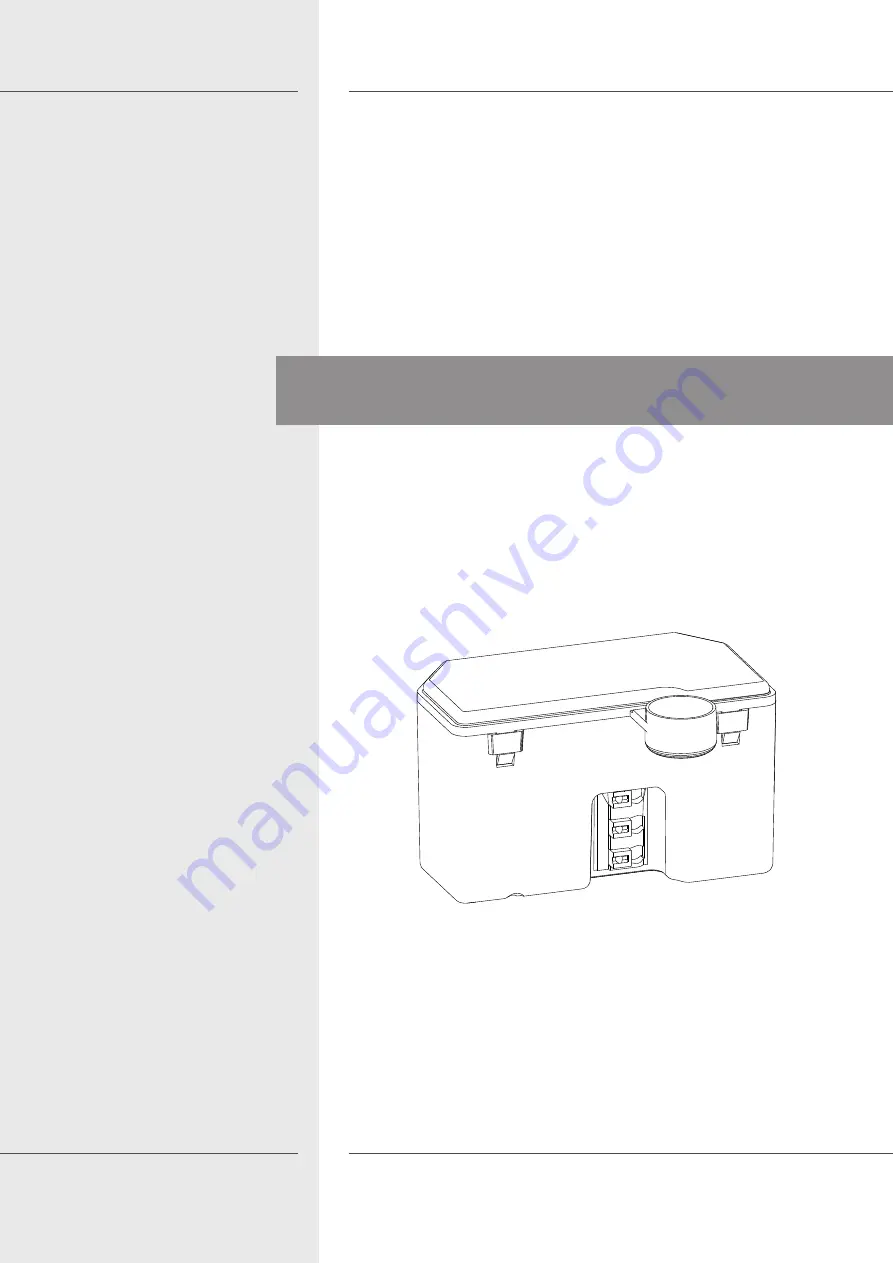
background image

DEU 

ENG

1


Alpha IP FSM 26001

Alpha IP

FSM 26001

133289.1650

Bedienungsanleitung

Summary of Contents for FSM 26001

Page 1: ...DEU ENG 1 Alpha IP FSM 26001 Alpha IP FSM 26001 133289 1650 Bedienungsanleitung ...

Page 2: ...immungsgemäße Verwendung 4 2 3 Sicherheitshinweise 4 3 Funktion 6 4 Geräteübersicht 7 4 1 Technische Daten 7 5 Inbetriebnahme 8 5 1 Montage 8 5 1 1 Montage in Unterputzdose 9 5 1 2 Montage in Aufputzdose 10 5 2 Gerät anlernen 11 6 Bedienung 12 7 Anzeigen 12 7 1 Statusanzeigen 12 7 2 Fehleranzeigen 13 8 Reinigen 14 9 Werkseinstellungen herstellen 14 10 Außerbetriebnahme 15 11 Entsorgen 15 ...

Page 3: ...und an nachfolgende Benutzer weiterzugeben Diese Anleitung sowie zusätzliche Alpha IP Systeminformationen sind stets aktuell unter www alphaip de zu finden Systeminformationen Funktionen und Bedienschritte aus der Anleitung des Alpha IP Access Point HAP 2001 sind zu berücksichtigen 1 2 Symbole Folgende Symbole werden in dieser Anleitung verwendet Gefahrzeichen Weist auf eine Gefahr mit möglichem P...

Page 4: ...A FSM 26001 ist eine Sys temkomponente des Alpha IP Systems und dient der ortsfesten Installation in wohnungsähnlichen Umgebungen der Schaltung angeschlossener elektronischer Verbraucher der Messung des Energieverbrauchs und kosten von angeschlosse nen Verbrauchern der Verbindung und Kommunikation weiterer Alpha IP Komponen ten Jegliche andere Verwendung Änderungen und Umbauten sind ausdrück lich ...

Page 5: ...ten verwendet werden Das Gerät nur in ortsfesten Installationen verwenden Das Gerät nur in trockener sowie staubfreier Umgebung betreiben Das Gerät keinem Einfluss von Feuchtigkeit Vibrationen ständiger Sonnen oder anderer Wärmeeinstrahlung Kälte oder mechanischen Belastungen aussetzen Sicherstellen dass keine Kinder mit dem Produkt oder der Verpa ckung spielen Gegebenenfalls Kinder beaufsichtigen...

Page 6: ...edienung oder über die Alpha IP App Über die Bedienoberfläche wird der Energieverbrauch angeschlossener Verbraucher sowie die Energiekosten dargestellt Die Kommunikation mit anderen Komponenten erfolgt über das Home matic HmIP Funkprotokoll Die Funk Übertragung wird auf einem nicht exklusiven Übertragungsweg realisiert weshalb Störungen nicht ausge schlossen werden können Störeinflüsse können z B ...

Page 7: ...0 W Lastart ohmsche Last cosφ 0 95 Relais Schließer 1 polig μ Kontakt Leitungsart und quer schnitt starre und flexible Leitung 0 75 1 5 mm Installation nur in Schalterdosen Gerätedosen ge mäß DIN 49073 1 oder Verbindungsdosen Aufputzdosen gemäß DIN 60670 1 Schutzart IP20 Messkategorie CAT III Umgebungstemperatur 10 bis 55 C Abmessung B x H x T 54 x 33 x 41 mm Gewicht 45 g Funkfrequenz 868 3 MHz 86...

Page 8: ...tröme von über 100 A erzeugen Schalten solcher Verbraucher führt zu vorzeitigem Verschleiß des Aktors In solchen Fällen wird die Verwendung von Einschaltstrombegrenzern an den Schaltausgängen empfohlen Der Stromkreis an dem das Gerät und die Last angeschlossen werden muss mit einem Leitungsschutzschalter gemäß EN60898 1 Auslösecha rakteristik B oder C max 16 A Nennstrom min 6 kA Abschaltvermö gen ...

Page 9: ...lant und realisiert werden Für die Steck Klemmanschlüsse sind nachfolgende Querschnitte ver wendbar starre Leitung 0 75 1 5 mm flexible Leitung 0 75 1 5 mm Leitungsenden 8 mm abisoliert 1 Netzspannung ausschalten und gegen Wiedereinschalten sichern 2 Phase L und Neutralleiter N zur Versorgung anschließen vgl Abb 3 Die geschaltete Phase 1 zum Verbraucher führen 4 Den Schalt Mess Aktor in eine geeig...

Page 10: ...anschlüsse sind nachfolgende Querschnitte ver wendbar starre Leitung 0 75 1 5 mm flexible Leitung 0 75 1 5 mm Leitungsenden 8 mm abisoliert 1 Netzspannung ausschalten und gegen Wiedereinschalten sichern 2 Phase L und Neutralleiter N zur Versorgung anschließen vgl Abb 3 Die geschaltete Phase 1 zum Verbraucher führen 4 Den Schalt Mess Aktor in eine geeignete Aufputzdose z B Abox 025 oder Abox 040 ei...

Page 11: ...t Gerät Anlernen auswählen Nach der Montage und Installation ist der Anlernmodus nach wiedereinschalten der Netzspannung für 3 Minuten aktiv Der Anlernmodus ist manuell über das Aus und wieder Einschalten der Netzspannung aktivierbar 3 Das Gerät erscheint automatisch in der App 4 Zur Bestätigung des Anlernvorgangs die letzten vier Ziffern der Gerä tenummer SGTIN in der App eingeben oder den beilie...

Page 12: ... Ge rätestatus 7 1 Statusanzeigen Anzeige Bedeutung Bedeutung Langes grünes Leuch ten Vorgang bestätigt Bestätigung vorge nommener Einstel lung Übertragung 1 x oranges 1 x grünes Leuchten Testanzeige Warten bis das Gerät bereit ist Kurzes oranges Blin ken Funkübertragung Warten bis die Über tragung beendet ist Kurzes oranges Blin ken alle 10 Sek Anlernmodus aktiv Die letzten vier Ziffern der Gerät...

Page 13: ... er reicht Duty Cycle Den Befehl erneut senden bei Duty Cy cle Überschreitung nach spätestens einer Stunde Gerät auf einen De fekt überprüfen z B mechanische Blocka de Funkstörungen besei tigen 6 x langes rotes Blin ken Gerät defekt Die Anzeige in der App beachten Das Gerät durch einen Fachhändler überprü fen lassen Das Gerät austau schen ...

Page 14: ...gen her stellen Durch Herstellen der Werkseinstellungen gehen alle vorgenommenen Einstellungen verloren 1 Das Gerät aus der Alpha IP App löschen 2 Netzspannung aus und wieder einschalten 9 9 Die Werkseinstellungen sind wiederhergestellt 9 9 Der Anlernmodus wird für 3 Minuten aktiviert vgl Gerät anlernen auf Seite 11 ...

Page 15: ...einschalten sichern 3 Alle bestehenden Kabel lösen 4 Das Gerät demontieren und ordnungsgemäß entsorgen 11 Entsorgen Das Gerät nicht im Hausmüll entsorgen Elektronische Geräte sind ent sprechend der Richtlinie über Elektro und Elektronik Altgeräte über die örtlichen Sammelstellen für Elektronik Altgeräte zu entsorgen Dieses Handbuch ist urheberrechtlich geschützt Alle Rechte vorbehalten Es darf wed...

Page 16: ...DEU ENG 16 Alpha IP FSM 26001 Alpha IP FSM 26001 133289 1650 Instruction manual ...

Page 17: ... Intended use 19 2 3 Safety notes 19 3 Function 21 4 Device overview 22 4 1 Technical Data 22 5 Commissioning 23 5 1 Installation 23 5 1 1 Installation in flush type box 24 5 1 2 Installation in surface box 25 5 2 Teach in of the device 26 6 Operation 27 7 Displays 27 7 1 Status displays 27 7 2 Error indications 28 8 Cleaning 29 9 Resetting factory settings 29 10 Decommissioning 30 11 Disposal 30 ...

Page 18: ... with the device These instructions must be kept and handed over to future users These instructions as well as constantly up to date additional Alpha IP system information can be found under www alphaip de System information functions and operating steps from the Alpha IP Access Point HAP 2001 instructions must be followed 1 2 Symbols The following symbols are used in this manual Hazard symbol Ind...

Page 19: ...e Alpha IP Switch Actuator and Meter flush type 5A FSM 26001 is a component of the Alpha IP System and serves for a fixed installation in environments of residential use for switching connected electronic consumers for measuring energy consumption and energy cost of connected consumers for the connection of further Alpha IP components and the commu nication with these Every other use modification ...

Page 20: ...vice in stationary installations Only operate the device in a dry and dust free environment Do not expose the device to the influence of humidity vibration continuous solar radiation or other types of radiation coldness or mechanical load Ensure that children do not play with this device or its packaging Children must be monitored if necessary Do not throw packaging material carelessly away Plasti...

Page 21: ...ct ed loads via smartphone app With the corresponding user interface you can have an over view of the energy consumption and costs of connected loads Communication with other components is performed via the Homematic HmIP radio protocol Radio transmission is realised on a non exclusive transmission path thus interference cannot be completely excluded Interference can be caused e g by switching pro...

Page 22: ...ad type ohmic load cosφ 0 95 Relay closing contact 1 pole μ contact Line type and line section rigid and flexible line 0 75 1 5 mm Installation only in switchboxes mounting boxes according to DIN 49073 1 or connection boxes surface boxes according to DIN 60670 1 Protection type IP20 Measurement category CAT III Ambient temperature 10 to 55 C Dimensions W x H x D 54 x 33 x 41 mm Weight 45 g Radio f...

Page 23: ... ohmic loads They can generate inrush currents of up to 100 A The switching of such consumers leads to a premature wear of the actuator In such cases the use of inrush current limiters at the switching outputs is recommended The circuit the device and the load are connected to must be protected with a circuit breaker according to EN60898 1 triggering characteristic B or C max 16 A nominal current ...

Page 24: ... the installer The following cross sections are applicable for the plug in clamping connections rigid wire 0 75 1 5 mm flexible wire 0 75 1 5 mm 8 mm insulation stripped off the wire 1 Disconnect from the mains network and secure against unintended activation 2 Connect phase L and neutral conductor N for supply see figure 3 Lead the switched phase 1 to the conductor 4 Insert the Switch Actuator an...

Page 25: ...the plug in clamping connections rigid wire 0 75 1 5 mm flexible wire 0 75 1 5 mm 8 mm insulation stripped off the wire 1 Disconnect from the mains network and secure against unintended activation 2 Connect phase L and neutral conductor N for supply see figure 1 Lead the switched phase 1 to the conductor 2 Insert the switch actuator and meter into a suitable surface box e g Abox 025 or Abox 040 se...

Page 26: ...tem Teach in device After assembly and installation the teach in mode is active for three minutes after switching on the mains voltage The teach in mode can be activated manually by switching the mains voltage on and off 3 The device will be displayed automatically in the app 4 For confirmation of the teach in process enter the last four digits of the device number SGTIN in the app or scan the sup...

Page 27: ... Status displays Display Meaning Meaning Long lighting in green Process confirmed Confirmation of per formed setting trans mission 1 lighting in orange and 1 lighting in green after plugging into a power outlet Test indication Wait until the device is ready Short flashing or ange Radio transmission Wait until the trans mission has ended Short flashing or ange once every 10 seconds Teach in mode ac...

Page 28: ...ssion limit reached duty cycle Re send the com mand after one hour at the latest in case of exceed ed duty cycle Check the device for defects e g mechanical blocking Eliminate radio in terference 6x long flashing red Device defective Observe the indi cation in the app Have the device checked by a spe cialist dealer Replace the device ...

Page 29: ...e 9 Resetting factory settings All settings will be lost when the factory settings are restored 1 Delete the device from the Alpha IP app 2 Switch the mains voltage off and on 9 9 The factory settings are reset 9 9 The teach in mode is activated for three minutes see Teach in of the device page 26 ...

Page 30: ...on 3 Loosen all connected cables 4 Uninstall the device and dispose of properly 11 Disposal Do not dispose of the device with domestic waste Electronic devices products must be disposed of according to the Direc tive for Waste Electrical and Electronic Equipment at the local collection points for waste electronic equipment This manual is protected by copyright All rights reserved It may not be cop...

Reviews: