background image

We reserve the right to modify technical specifications without prior notice.
UK830304/190326 

© Alpha-InnoTec GmbH

HEAT PUMPS

Operat i ng   Manual

Inside installation

AIR/WATER

UK

LW 100 - LW 190
LW 150H(L)

Summary of Contents for LW 100

Page 1: ...We reserve the right to modify technical specifications without prior notice UK830304 190326 Alpha InnoTec GmbH HEAT PUMPS Operating Manual Inside installation AIR WATER UK LW 100 LW 190 LW 150H L ...

Page 2: ...rameters for the respective model This operating manual is intended only for persons assigned to work on or operate the unit Treat all constituent parts confidentially The information contained herein is protected by copyright No part of this information may be reproduced transmitted copied stored in electronic data systems or translated into another language either wholly or in part without the e...

Page 3: ...AL OF THE SCREEN 20 COMMISSIONING 22 Safety temperature limiter 22 DISMANTLING 23 TECHNICAL DATA SCOPE OF DELIVERY LW 100 LW 190 24 LW 150H L 26 PERFORMANCE CURVES Heating capacity COP power consumption Heat pump pressure loss LW 100 28 LW 120 29 LW 150 30 LW 190 31 LW 150H L 32 DIMENSIONAL DRAWINGS AND INSTALLATION PLANS Dimensional drawings LW 100 LW 120 LW 150H 33 LW 150HL 34 Installation plans...

Page 4: ...t is operationally safe when used for the intended purpose The construction and design of the unit conform to the state of the art all relevant DIN VDE regulations and all relevant safety regulations Every person who performs work on the unit must have read and understood the operating manual prior to starting any work This also applies if the respective per son has already worked with such a unit...

Page 5: ... lation systems is not permissible The use of the cooled air for cooling purposes is not permitted CAUTION In the air outlet area the air temperature is ca 5 K below the ambient temperature Under certain climatic conditions there fore an ice layer can form in the air out let area Install the heat pump so that the air blower does not blow in the direction of footpaths Customer service For technical...

Page 6: ...ntity recording referred to as WME in this manual The WME is mandatory with air water heat pumps With brine water and water water heat pumps a WME is only required when the feed temperature is 35 C The WME must record the total warm energy release heating and hot water in the building In heat pumps with heat quantity recording the analysis is conducted by the regulator The regulator displays the t...

Page 7: ...s expansion vessels circulating pumps fil ters dirt traps should be inspected as well as cleaned as needed at the very least annually by a qualified heating or cooling system technician It is a good idea to have a maintenance contract with a specialist company The company will conduct the required maintenance at regular intervals CLEANING AND FLUSHING OF UNIT COMPONENTS CAUTION Unit components may...

Page 8: ... side Proceed as follows Inspect delivery for outwardly visible signs of damage Check to make sure that delivery is complete Any defects or incorrect deliveries must be claimed immediately NOTICE Note the model Check the air blow out direction of the unit Units with the abbreviation L in the model designation blow the air out to the left when viewed from the control side Overview Technical data sc...

Page 9: ... LOCATION To prevent damage during transport always transport the unit to final installation location in its original packag ing using a lifting truck If it is not possible to transport the unit to the final instal lation location using a lifting truck you can also transport the heat pump using a hand truck or with pipes DANGER Several people are required to transport the unit Do not underestimate...

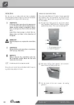
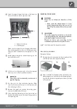
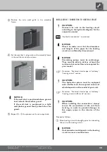
Page 10: ...move the sealing grommet INSTALLATION Set the unit on a stable solid and level preferably sound insulated surface Make sure that the foundation is designed for the weight of the heat pump CAUTION In the air outlet area the air temperature is ca 5 K below the ambient temperature Under certain climatic conditions there fore an ice layer can form in the air outlet area Install the heat pump so that t...

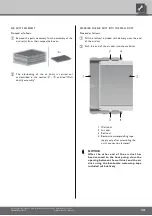
Page 11: ...g surface Remove the pipes and re place the sealing grom mets on the back side of the unit If the electrical connections will not be carried out directly thereafter mount the lower facing panel on the operating side MOUNTING THE AIR DUCTS NOTICE Note the air blow out direction of the unit Units with the abbreviation L in the model designation blow the air out to the left when viewed from the contr...

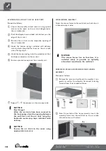
Page 12: ...he chip board included with delivery Install the wall duct in the masonry from the house exterior This can either be done during the construction phase by means of sealing NOTICE Mount the wall ducts 1 cm above the fin ished outer facade 1 Masonry of the house exterior 2 Insert the wall duct in the masonry 1 cm above the finished outer facade or retrofit using foam in the masonry 1 Finished outer ...

Page 13: ...ll seal 4 Bentonite waterproofing tape apply only after assembling the unit s connection fastener NOTICE After the other end of the air duct has been secured to the heat pump close the opening between the wall duct and the air duct using the bentonite waterstop tape included with delivery AIR DUCTS ASSEMBLY Proceed as follows Remove the parts necessary for the assembly of the air duct s from their...

Page 14: ... SECURING THE AIR DUCT ON THE HEAT PUMP Proceed as follows Clip on the assembly rail and secure it using special screws to the spots on the air duct designated as the air intake side Stick the adapter base included with delivery on the edge of the air duct Position the air duct on the respective opening of the air intake side Hook the tension springs included with delivery into the holes provided ...

Page 15: ...ke sure that the diameters and lengths of the pipes for the heating circuit are sufficiently dimensioned NOTICE Circulating pumps must be multi stage They must be able to deliver at least the minimum hot water flow rate required for your model Overview Technical data scope of delivery heating circuit section CAUTION The hydraulic system must be equipped with a buffer tank the required volume of wh...

Page 16: ...lus tration Discharge of the condensate into the sewage system is permitted only via a funnel siphon which must be acces sible at all times Install shut off devices for the hot water outflow forward flow and hot water inflow return flow on the heat pump side NOTICE During installation of the shut off devices the liquefier of the heat pump can be flushed if necessary CAUTION The condenser may be fl...

Page 17: ...ntegrate the hot water tank in the heat pump system according to the hydraulic diagram for your system Hydraulic connection instructions Pressure relief Equip the heating circuit in accordance with local stand ards and directives with a safety valve and an expansion tank Also install filling and emptying devices shut off devices and non return valves in the heating circuit Overflow valve Always us...

Page 18: ...ged at contactor for 2 3 or 4 kW 6kW For further information see the adhesive label on the electric heating element NOTICE Using a suitable network cable the control element of the heat and heat pump regulator can be connected with a computer or a network allowing the heating and heat pump regulator to be controlled from there Electrical connections Observe the following when performing all work D...

Page 19: ... be used to hang the control element on the front facade of the unit If such a connection is desired lay a category 6 screened network cable with RJ 45 plug through the unit parallel to the heating and heat pump regulator control cable already present when making the connections and lead it through the front panel of the unit Close electrical switch cabinet of unit Attach the lower facing panels F...

Page 20: ...ed remotely One pre condition is that a screened network cable category 6 be installed through the unit when installing the unit Operating manual for the heating and heat pump regulator version Qualified technician Web server section If this network cable is available insert the network cable s RJ 45 plug into the left bushing of the control element NOTICE The network cable can be exchanged at any...

Page 21: ...ck the screen s snap in lugs in place in the slots provided on the front of the facade Next on the opposite side moving upwards lock the screen s snap in lugs in place in the slots provided on the front of the facade Finally press the screen s upper snap in lugs into the slots provided on the front of the facade REMOVING THE SCREEN In order to remove the screen the snap in lugs must first be loose...

Page 22: ... circuit must be flushed filled and thoroughly bled t All valves and shut off devices of the heating cir cuit must be open t All pipe systems and components of the system must be sealed Carefully fill out and sign the completion report for heat pump systems Completion report for heat pump systems In Germany Send completion report for heat pump systems and general checklist to the manufacturer s fa...

Page 23: ...stem technicians are allowed to remove the unit from the system DANGER Only qualified cooling system technicians are allowed to dismantle the unit and its components CAUTION Recycle or provide for proper disposal of unit components refrigerants and oil in accordance with the applicable regula tions standards and directives REMOVAL OF THE BUFFER BATTERY CAUTION Before scrapping the heating and heat...

Page 24: ...ing circuit Heat source Refrigerant Refrigerant type ı Quantity ı kg Free cross section air channels mm Cross section condensate water length from unit mm ı m Electric Voltage code ı all pole circuit breaker heat pump ı A Voltage code ı circuit breaker control voltage ı A Voltage code ı circuit breaker electric heating element ı A Heat Pump Effective power consumption in standard point A7 W35 acco...

Page 25: ...230V 50Hz ı B10 3 N PE 400V 50Hz ı C16 5 5 3 2 ı 10 6 6 1 ı 0 75 0 75 15 2 52 ı 26 20 9 ı 6 ı 3 ı ı ı ı 813048 e LW 120 ı ı ı 12 5 ı 3 9 10 9 ı 3 0 11 5 ı 3 2 13 8 ı 4 1 9 1 ı 2 6 20 58 60 20 35 50 50 3400 25 1200 ı 2400 ı 3000 0 11 ı 2200 ı 2 220 G1 AG R404A ı 4 5 594 x 594 30 ı 1 3 PE 400V 50Hz ı C16 1 N PE 230V 50Hz ı B10 3 N PE 400V 50Hz ı C10 3 2 ı 6 2 ı 0 74 9 7 61 ı 28 20 6 ı 4 ı 2 ı ı ı ı ...

Page 26: ...ing circuit Heat source Refrigerant Refrigerant type ı Quantity ı kg Free cross section air channels mm Cross section condensate water length from unit mm ı m Electric Voltage code ı all pole circuit breaker heat pump ı A Voltage code ı circuit breaker control voltage ı A Voltage code ı circuit breaker electric heating element ı A Heat Pump Effective power consumption in standard point A7 W35 acco...

Page 27: ...5 700 ı 1700 ı 2000 0 07 ı 1700 ı 2 255 G1 AG R407C ı 4 3 594 x 594 30 ı 1 3 PE 400V 50Hz ı C16 1 N PE 230V 50Hz ı B10 3 N PE 400V 50Hz ı C16 2 9 ı 5 7 ı 0 75 12 64 ı 30 20 9 ı 6 ı 3 ı ı ı ı 813033 c We reserve the right to modify technical specifications without prior notice UK830304 190326 Alpha InnoTec GmbH ...

Page 28: ...35 Temp C p bar 0 0 0 1 0 2 0 3 0 4 0 0 1 0 2 0 3 0 4 0 5 0 m h p Legend UK823129L 170408 Volume flow heating water Temp Temperature heat source Qh Heating capacity Pe Power consumption COP Coefficient of performance efficiency rating p Pressure loss heat pump VD Compressor s We reserve the right to modify technical specifications without prior notice UK830304 190326 Alpha InnoTec GmbH LW 100 Perform...

Page 29: ... 30 35 Temp C p bar 0 0 0 1 0 2 0 3 0 4 0 0 1 0 2 0 3 0 4 0 5 0 m h p Legend UK823129L 170408 Volume flow heating water Temp Temperature heat source Qh Heating capacity Pe Power consumption COP Coefficient of performance efficiency rating p Pressure loss heat pump VD Compressor s We reserve the right to modify technical specifications without prior notice UK830304 190326 Alpha InnoTec GmbH Performanc...

Page 30: ...0 5 10 15 20 25 30 35 Temp C p bar 0 0 0 1 0 2 0 3 0 4 0 0 1 0 2 0 3 0 4 0 5 0 m h p Legend UK823129L 170408 Volume flow heating water Temp Temperature heat source Qh Heating capacity Pe Power consumption COP Coefficient of performance efficiency rating p Pressure loss heat pump VD Compressor s We reserve the right to modify technical specifications without prior notice UK830304 190326 Alpha InnoTec ...

Page 31: ...10 5 0 5 10 15 20 25 30 35 Temp C p bar 0 0 0 1 0 2 0 3 0 0 1 0 2 0 3 0 4 0 5 0 6 0 m h p Legend UK823129L 170408 Volume flow heating water Temp Temperature heat source Qh Heating capacity Pe Power consumption COP Coefficient of performance efficiency rating p Pressure loss heat pump VD Compressor s We reserve the right to modify technical specifications without prior notice UK830304 190326 Alpha Inn...

Page 32: ...5 10 15 20 25 30 35 Temp C p bar 0 0 0 1 0 2 0 3 0 4 0 0 1 0 2 0 3 0 4 0 5 0 m h p Legend UK823129L 170408 Volume flow heating water Temp Temperature heat source Qh Heating capacity Pe Power consumption COP Coefficient of performance efficiency rating p Pressure loss heat pump VD Compressor s We reserve the right to modify technical specifications without prior notice UK830304 190326 Alpha InnoTec Gm...

Page 33: ...ew from left D Side view from right E Rear view LR Air direction Item Designation 1 Control panel 2 Hot water outlet flow G 1 DIN ISO 228 3 Hot water inlet return G 1 DIN ISO 228 4 Bushings for electrical sensor cables 5 Condensate hose ø i 30 Length from device 1m We reserve the right to modify technical specifications without prior notice UK830304 190326 Alpha InnoTec GmbH Dimensional drawings LW...

Page 34: ...ide view from left D Side view from right E Rear view LR Air direction Item Designation 1 Control panel 2 Hot water outlet flow G 1 DIN ISO 228 3 Hot water inlet return G 1 DIN ISO 228 4 Bushings for electrical sensor cables 5 Condensate hose ø i 30 Length from device 1m We reserve the right to modify technical specifications without prior notice UK830304 190326 Alpha InnoTec GmbH LW 150HL Dimensio...

Page 35: ...ct 700x700x450 FA Finished outer façade 3 Accessory air duct 700x700x1000 LR Air direction 4 Accessory air duct bend 700x700x750 BS Operator side 5 Installation above ground level Accessory weather guard 845x850 FWS Finished wall thickness KA Condensate discharge 6 Installation in light well Accessory rain guard 845x850 G Section installation in light well 7 Provided by customer light well with wa...

Page 36: ...nation V2 Version 2 1 Accessory wall duct 800x800x420 OKF Top edge of finished floor 2 Accessory air duct 700x700x450 FA Finished outer façade 3 Accessory air duct 700x700x1000 LR Air direction 4 Accessory air duct bend 700x700x750 BS Operator side 5 Installation above ground level Accessory weather guard 845x850 FWS Finished wall thickness KA Condensate discharge 6 Installation in light well Access...

Page 37: ...lation above ground level Accessory weather guard 845x850 BS Operator side FWS Finished wall thickness 6 Installation in light well Accessory rain guard 845x850 KA Condensate discharge G Section installation in light well 7 Provided by customer light well with water drain min exposed cross section 0 6m Tilt dimension of heat pumps without tank 1540 Note if the buffer tank beneath is replaced with ...

Page 38: ...uter façade 4 Accessory air duct bend 700x700x750 LR Air direction 5 Installation above ground level Accessory weather guard 845x850 BS Operator side FWS Finished wall thickness 6 Installation in light well Accessory rain guard 845x850 KA Condensate discharge G Section installation in light well 7 Provided by customer light well with water drain min exposed cross section 0 6m Tilt dimension of hea...

Page 39: ...uct 800x800x420 OKF Top edge of finished floor 2 Accessory air duct 700x700x450 FA Finished outer façade 3 Accessory air duct 700x700x1000 LR Air direction 4 Accessory air duct bend 700x700x750 BS Operator side 5 Installation above ground level Accessory weather guard 845x850 FWS Finished wall thickness KA Condensate discharge 6 Installation in light well Accessory rain guard 845x850 G Section insta...

Page 40: ...ide view from left D Side view from right E Rear view LR Air direction Item Designation 1 Conrol panel 2 Condensate hose ø i 30 Length from device 1m 3 Bushings for electrical sensor cables 4 Hot water outlet flow G 5 4 DIN ISO 228 5 Hot water inlet return G 5 4 DIN ISO 228 We reserve the right to modify technical specifications without prior notice UK830304 190326 Alpha InnoTec GmbH LW 150 LW 190 ...

Page 41: ...esignation V1 Version 1 1 Accessory wall duct 800x800x420 OKF Top edge of finished floor 2 Accessory air duct 700x700x450 FA Finished outer façade 3 Accessory air duct 700x700x1000 LR Air direction 4 Accessory air duct bend 700x700x750 BS Operator side 5 Installation above ground level Accessory weather guard 845x850 FWS Finished wall thickness KA Condensate discharge 6 Installation in light well Ac...

Page 42: ...r duct 700x700x450 FA Finished outer façade 3 Accessory air duct 700x700x1000 LR Air direction 4 Accessory air duct bend 700x700x750 BS Operator side 5 Installation above ground level Accessory weather guard 845x850 FWS Finished wall thickness KA Condensate discharge 6 Installation in light well Accessory rain guard 845x850 G Section installation in light well 7 Provided by customer light well wit...

Page 43: ...Installation above ground level Accessory weather guard 845x850 BS Operator side FWS Finished wall thickness 6 Installation in light well Accessory rain guard 845x850 KA Condensate discharge G Section installation in light well 7 Provided by customer light well with water drain min exposed cross section 0 6m Tilt dimension of heat pumps without tank 1740 Note if the buffer tank beneath is replaced...

Page 44: ... Accessory air duct 700x700x1000 LR Air direction 4 Accessory air duct bend 700x700x750 BS Operator side 5 Installation above ground level Accessory weather guard 845x850 FWS Finished wall thickness KA Condensate discharge 6 Installation in light well Accessory rain guard 845x850 G Section installation in light well 7 Provided by customer light well with water drain min exposed cross section 0 6 m...

Page 45: ... F F F F F 2 F F F F F F C F A 9 9B 9D F F F F F F F F F F F F 08 1 1 1 F F F F F F A 9 9 9D B F F F F 9 9 9 F F F F F F F F F F F F F F F F F F F F F F F F F F 8F F 9 F F F F F 9 F F 8F 4 F FE 9 F F F 4 F 3 DB F 36 6 3 4 B D E 0 3 5 B D E B D E 0 3 5 B D E 9 6 6 5 F BE F4F BED FF B0 F4F B0 4 6 7 6 F F We reserve the right to modify technical specifications without prior notice UK830304 190326 Alp...

Page 46: ...2 2 2 H H 2H 2H H H H H H H 3 2H 2 2 2 2 H H 2H H B H H H H H C 0 5 1 A B C H H H A B C B C F 1 4 6 B C F 67 7 1 H 7 B C F 1 4 6 B C F 17 C7 666 0 5 H 5 H E 4 1 B1 7H D 7 7H 7 5 7 H H 7 7 8 We reserve the right to modify technical specifications without prior notice UK830304 190326 Alpha InnoTec GmbH LW 100 LW 120 Circuit diagram 1 3 ...

Page 47: ...H H H H H H H H H H H H H H H H H H 2H C 0 5 H C B 5 H H 1 A C 4 H H 9H 5 H HF 1 H H H H H H H H H H H 2 2 H H 2H H H H B C F 1 4 6 B C F 67 7 1 H 7 B C F 1 4 6 B C F 17 C7 666 0 5 H 5 H E 4 1 B1 7H D 7 7H 7 5 7 H H 7 7 8 We reserve the right to modify technical specifications without prior notice UK830304 190326 Alpha InnoTec GmbH Circuit diagram 2 3 LW 100 LW 120 ...

Page 48: ...H H 0 0 H H 9H H H H H H H 0 4 H 0 H H 9H 5 H HF 5 H H 2H FH 9H H 5 5 0 F B C F 1 4 6 B C F 67 7 1 H E B C F 1 4 6 B C F 47 7 1 0 5 H 5 H E 4 1 B1 7H D 7 7H 7 5 7 H H 7 7 8 We reserve the right to modify technical specifications without prior notice UK830304 190326 Alpha InnoTec GmbH LW 100 LW 120 Circuit diagram 3 3 ...

Page 49: ...H 3 H H 5 H H H H H C 5 H H H A B C 1 0 5 F A B C H H H H H H H H H H H H 0 5 H 5 B H H H H B B H 1 H A B C H C C C A B C B C F 1 4 6 B C F 7 7 1 H 7 B C F 1 4 6 B C F 17 C7 666 0 C 5 6 H 5 H E 4 1 B4 7H D 7 7H 7 5 7 H H 7 7 8 We reserve the right to modify technical specifications without prior notice UK830304 190326 Alpha InnoTec GmbH Circuit diagram 1 3 LW 150 LW 190 ...

Page 50: ...C H C C H H H 0 5 H H H H H H H H H H H H H H H 2 2 H H 2H H H H 4 1 H H 9H 5 H HF 5 H H H H H H H H H H H H H H H H H H F A C H H H B C F 1 4 6 B C F 7 7 1 H 7 B C F 1 4 6 B C F 17 C7 666 0 C 5 6 H 5 H E 4 1 B4 7H D 7 7H 7 5 7 H H 7 7 8 We reserve the right to modify technical specifications without prior notice UK830304 190326 Alpha InnoTec GmbH LW 150 LW 190 Circuit diagram 2 3 ...

Page 51: ... F 5 H 2H 1BH 9H H H H H 1 H H H H B H H C 0 0 H 9H H H H H H 9H H H H 6 B C F 1 4 6 B C F 7 7 1 H E B C F 1 4 6 B C F 47 7 1 0 C 5 6 H 5 H E 4 1 B4 7H D 7 7H 7 5 7 H H 7 7 8 We reserve the right to modify technical specifications without prior notice UK830304 190326 Alpha InnoTec GmbH Circuit diagram 3 3 LW 150 LW 190 ...

Page 52: ...I I 0 3 3 A3 3 I I 3I I 3I 3 3 A3 I I 3I 3I I I I I I 0 I 4 I I 2 1 6 A AB C D A A D I I I0 I I I I I 6 A A C D G 2 5 7 A C D G 8 8 2 I 8 A C D G 2 5 7 A C D G 28 D8 777 1 D 6 I F A 5 2 C 8I E 8 8I 8 6 8 I I 08 8 9 We reserve the right to modify technical specifications without prior notice UK830304 190326 Alpha InnoTec GmbH LW 150H L Circuit diagram 1 3 ...

Page 53: ...A I I I I I I0 I I I0 I B A D I I I I I I I I I I G 2 I D B A D A D 3I I I I I 6 I 2 I I I I I C 3 3 I I 3I I I I0 I I I I I I I I I 5 6 I 1 I I A C D G 2 5 7 A C D G 8 8 2 I 8 A C D G 2 5 7 A C D G 28 D8 777 1 D 6 I F A 5 2 C 8I E 8 8I 8 6 8 I I 08 8 9 We reserve the right to modify technical specifications without prior notice UK830304 190326 Alpha InnoTec GmbH Circuit diagram 2 3 LW 150H L ...

Page 54: ... 1 1 I I I I I I I I I 1 5 I 1 I0 I I 6 I IG A 6 I I 3IA GI I I 6 6 1 G A C D G 2 5 7 A C D G A 8 8 2 I F A C D G 2 5 7 A C D G 78 A8 2 1 D 6 I F A A 5 2 C 8I E 8 8I 8 6 8 I I 08 8 9 We reserve the right to modify technical specifications without prior notice UK830304 190326 Alpha InnoTec GmbH LW 150H L Circuit diagram 3 3 ...

Page 55: ... 461 LW 250L 100 467 LW 120 100 462 LW 150H 100 470 LW 120L 100 463 LW 150HL 100 471 LW 150 100 464 LW 320H 100 472 LW 190 100 465 LW 320HL 100 473 EC DIRECTIVES STANDARDISED EN 98 37 EG EN 378 EN 349 2006 95 EG EN 60529 EN 60335 1 2 40 2004 108 EG EN ISO 12100 1 2 EN 55014 1 2 EN ISO 13857 EN 61000 3 2 3 3 NATIONAL STANDARDS DIRECTIVES DE AT CH BGR 500 Teil 2 NEV SR 743 26 DIN 8901 Company Place ...

Page 56: ...56 We reserve the right to modify technical specifications without prior notice UK830304 190326 Alpha InnoTec GmbH ...

Page 57: ...tection screen installed q Yes Rotary field of fan q O K Heat source brine heat source water Heat source volume flow q O K Motor protection setting A Rotary field of heat source circulating pump q O K Heat source filled air free and sealed q Yes Brine Frost protection down to C Type of anti freeze agent please enter Water Water quality OK q Yes Well units q Yes Other heat source q Yes Heat pump In...

Page 58: ......

Page 59: ...h the date you will be contacted by phone I hereby confirm that all preliminary work required for commissioning has been carried out and completed The system is ready for operation Requested commissioning Heat pumps up to 33 kW excluding P Series Heat pumps above 33 kW and P Series IBN Item No 160 001 q IBN P5 Item No 160 003 q IBN 5 Item No 160 002 q IBN VP5 Item No 160 004 q IBN VP EW Item No 16...

Page 60: ......

Page 61: ...61 We reserve the right to modify technical specifications without prior notice UK830304 190326 Alpha InnoTec GmbH Space for notes ...

Page 62: ...c fr DE Alpha InnoTec GmbH Industriestrasse 3 95359 Kasendorf Tel 49 0 9228 99 06 190 Fax 49 0 9228 99 06 199 Hotline 49 0 171 26 63 326 info alpha innotec com www alpha innotec com AT Peter Rieß Mannheimstrasse 11 4040 Linz Tel 43 0 732 24 42 018 Fax 43 0 732 24 42 014 peter riess liwest at BE NATHAN Import Export N V S A Lozenberg 4 1932 Zaventem Tel 32 0 27 21 15 70 Fax 32 0 27 25 35 53 info na...

Page 63: ...pact 73 6921 RZ Duiven Tel 31 0 26 445 98 45 Fax 31 0 26 445 93 73 info nathan nl www nathan nl NO Alpha InnoTec Norge AS Langgaten 59 4306 Sandnes Tel 47 0 51 6605 95 Fax 47 0 51 6605 94 info alpha innotec no www alpha innotec no PL Hydro Tech ul Zakladowa 4d 62 510 Konin Tel 48 0 63 245 34 79 Fax 48 0 63 242 37 28 hydro hydro tech pl www alpha innotec pl www hydro tech pl PT GudEnergy Energias R...

Page 64: ......

Reviews: