background image


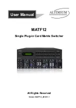
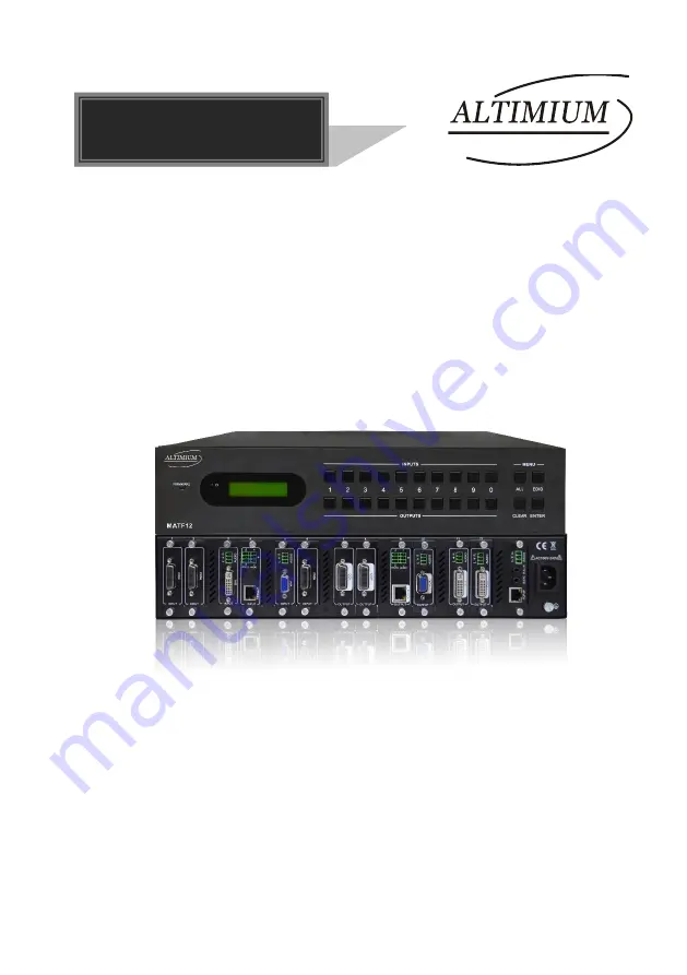
MATF12 

Single Plug-in Card Matrix Switcher 


All Rights Reserved 

Version: MATF12_2016V1.1

User Manual


Summary of Contents for MATF12

Page 1: ...MATF12 Single Plug in Card Matrix Switcher All Rights Reserved Version MATF12_2016V1 1 User Manual ...

Page 2: ...erties of the trademark owner No part of this publication may be copied or reproduced without prior written consent FCC Statement This equipment generates uses and can radiate radio frequency energy and if not installed and used in accordance with the instructions may cause harmful interference to radio communications It has been tested and found to comply with the limits for a Class B digital dev...

Page 3: ... to rain moisture or install this product near water Do not put any heavy items on the extension cable in case of extrusion Do not remove the housing of the device as opening or removing housing may expose you to dangerous voltage or other hazards Install the device in a place with fine ventilation to avoid damage caused by overheat Keep the module away from liquids Spillage into the housing may r...

Page 4: ...5 2 2 3 I VG O VG 6 2 2 4 I DV O DV 7 2 2 5 I HD O HD 8 3 System Connection 11 3 1 Usage Precautions 11 3 2 System Diagram 11 3 3 Connection Procedures 12 3 4 Application 12 4 Operations 13 4 1 Front Panel Control 13 4 1 1 Switching I O connection 13 4 1 2 EDID Learning 13 4 1 3 Inquiry 14 4 1 4 Clear operation 14 4 2 IR Control 15 4 3 RS232 Control 16 4 3 1 Installation uninstallation of RS232 Co...

Page 5: ...ommunication software 27 4 4 3 Control via web based GUI 28 4 4 4 Port Management 33 5 Firmware Upgrade 34 6 Specification 35 6 1 Main Unit 35 6 2 Signal Cards 35 6 2 1 I TP O TP 35 6 2 2 I SD O SD 36 6 2 3 I VG O VG 36 6 2 4 I DV O DV 36 6 2 5 I HD O HD 37 7 Panel Drawing 38 8 Troubleshooting Maintenance 39 9 After sales Service 40 ...

Page 6: ... handle all the audiovisual management including the switching driving scaling etc 1 2 Features 12 card slots for flexible input output combination Comprehensive signal card compatibility DVI SDI VGA HDBT Automatically recognize input output signal card Powerful EDID management UPnP enables quick connection to GUI HDCP Compliant Seamless AV distribution through different AV signal Controllable via...

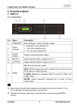
Page 7: ...buttons ranges from 0 9 OUTPUTS Output selection buttons ranges from 0 9 MENU ALL Select all inputs outputs EDID EDID management button enable input port to learn the EDID data from output devices CLEAR Withdraw an operation before it comes into effect exit inquiry mode ENTER confirm operation long press 3s or more to enter inquiry mode 1 Input output channels are recognized as double digit so pre...

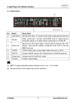
Page 8: ...CP IP TCP IP control port connect with control device e g a PC IR EYE Connect with IR receiver 5V with carrier to control the switcher Power port Connect with 100 240V AC outlet Ground Connect to grounding 1 MATF12 supports flexible card connection to form 11x1 1x11 matrix 2 Pictures shown in this manual are only for reference INPUT SDI LOOP 1 2 3 4 5 7 12 11 RS232 Tx Rx TCP IP VGA INPUT AUDIO L R...

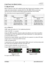
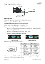
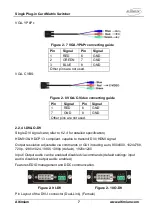
Page 9: ...g Audio I HD HDMI Analog Audio O HD HDMI Analog Audio 2 2 1 I TP O TP HDBT signal card refer to 6 2 1 for detailed specification HDMI1 3 HDCP1 3 compliant Work with HDBT transmitter receiver to attain long distance up to 70m via qualified CAT6 cable up to 70m via qualified CAT6 cable transmission for 1080p signal and bi directional RS232 control Real time work status indicator green LED blinks onc...

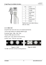
Page 10: ...es with their half color cables 2 2 2 I SD O SD Single SDI input card refer to 6 2 2 for detailed specification Transmit high definition 3G SDI HD SDI SDI signal Resolution range 1080p 1080i 720p Transmit 1080p signal up to 100m INPUT card 1 loop output for local monitoring OUTPUT card 1 SDI and 1 loop output Figure 2 3 I SD Figure 2 4 O SD The BNC connector is shown as the figure below ...

Page 11: ...ds or GUI Resolution range for VGA signal 800x600 1024x768 720p 1280x1024 1080i 1080p default 1920x1200 Resolution range for YPbPr signal 720p 1080i 1080p Resolution range for CVBS signal 480i 576i Figure 2 5 I VG Figure 2 6 O VG Pin layout of the VGA connectors female Pin Signal Pin Signal 1 RED 9 KEY PWR 2 GREEN 10 GND 3 BLUE 11 ID0 RES 4 ID2 RES 12 ID1 SDA 5 GND 13 HSync 6 RED_RTN 14 VSync 7 GR...

Page 12: ...d 2 2 4 I DV O DV Single DVI signal card refer to 6 2 4 for detailed specification HDMI1 3 HDCP1 3 compliant capable to transmit DVI HDMI signal Output resolution adjustable via commands or GUI including auto 800x600 1024x768 720p 1280x1024 1080i 1080p default 1920x1200 Input Output audio can be enabled disabled via commands default settings input audio disabled output audio enabled Features EDID ...

Page 13: ...hield 11 T M D S Data1 3 Shield 23 T M D S Clock 12 T M D S Data3 13 T M D S Data3 2 2 5 I HD O HD Single HDMI signal card refer to 6 2 5 for detailed specification HDMI1 3 HDCP1 3 compliant capable to transmit DVI HDMI signal Auto detect input resolution Max resolution 1080p 60Hz Output resolution adjustable via commands or GUI including auto 800x600 1024x768 720p 1280x1024 1080i 1080p default 19...

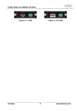
Page 14: ...Single Plug in Card Matrix Switcher Altimium 9 www altimium com Figure 2 11 I HD Figure 2 12 O HD ...

Page 15: ... Signal No Signal 1 TMDS Data 2 11 TMDS Clock Shield 2 TMDS Data 2 Shield 12 TMDS Clock 3 TMDS Data 2 13 CEC 4 TMDS Data 1 14 N C 5 TMDS Data 1 Shield 15 SCL 6 TMDS Data 1 16 SDA 7 TMDS Data 0 17 DDC CEC Ground 8 TMDS Data 0 Shield 18 5V Power 9 TMDS Data 0 19 Hot Plug Detect 10 TMDS Clock TMDS Clock Shield ...

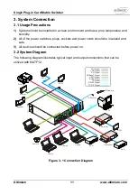
Page 16: ...lated and safe 3 All devices should be connected before power on 3 2 System Diagram The following diagram illustrates typical input and output connections that can be utilized with MATF12 Figure 3 1 Connection Diagram 11 12 13 14 12 13 14 11 14 Laptop Projector PC Monitor HDTV Receiver Transmitter Camera VGA Signal DVI Signal HDMI Signal HDBaseT Signal RS232 Signal TCP IP Signal SDI Signal IR Sign...

Page 17: ... to enable IR control Step6 Connect control device e g a PC to the RS232 port to enable serial control Step7 Connect control device e g a PC to the TCP IP port to enable TCP IP control Step8 Insert 100 240V AC outlet via the included power cord 3 4 Application Owing to its flexible card design MATF12 is an all in one solution which is ideal for different projects such as public display educational...

Page 18: ...put Operation INPUT OUTPUT ENTER Example transfer input 01 to output 12 2 To convert an input to several outputs Operation INPUT OUTPUT OUTPUT ENTER Example Switch input 2 to output 2 4 3 To convert an input to all outputs Operation input ALL ENTER Example Convert input 02 to all outputs 4 1 2 EDID Learning MATF12 features EDID management to maintain compatibility between all devices One input por...

Page 19: ...ution In inquiry mode press output channel to check its resolution Correspondence between inputs and outputs OUTPUT ENTER 4 1 4 Clear operation Function clear the previous operations before pressing ENTER to enforce it Press CLEAR can only erase the operations not confirmed by pressing ENTER 1 Input output channels are recognized in double digit press 01 09 instead of 1 9 2 The input delay time be...

Page 20: ...IR remote shown as below Standby enter exit standby mode INPUTS input selection buttons channels 1 9 should be pressed as 01 09 Function Buttons share the same operation with front panel buttons ENTER confirm operation long press 3 seconds or more to enter inquiry mode Note navigation buttons are unavailable OUTPUTS output selection buttons channels 1 9 should be pressed as 01 09 ...

Page 21: ...on of RS232 Control Software Installation Copy the control software file to the computer connected with MATF12 Uninstallation Delete all the control software files in corresponding file path 4 3 2 Basic Settings Firstly connect MATF12 with an input device and an output device Then connect it with a computer which is installed with RS232 control software Double click the software icon to run this s...

Page 22: ...rameters of COM number bound rate data bit stop bit and the parity bit correctly only then will you be able to send command in Command Sending Area Parameter Configuration area Parameter Configuration area Monitoring area indicates whether the command sent works Command Sending area ...

Page 23: ...cation Protocol Baud rate 9600 Data bit 8 Stop bit 1 Parity bit none Command Description Feedback System Command Type Inquire the model MATF12 Lock Lock the front panel buttons System Locked Unlock Unlock the front panel buttons System Unlock Version Inquire the firmware version VX X X MessageOff Turn off the feedback from the com port It only shows switcher OK MessageOff MessageOn Turn on the fee...

Page 24: ...V 02 06 Clear Y Clear the preset command Y Clear F1 EDIDMInit Reset factory default EDID EDIDMInit EDIDM X B Y Manage EDID enable input Y learn EDID data from output X EDIDM07B03 PWON Work normally PWON PWOFF Enter standby mode PWOFF STANDBY Enter standby mode can be awaken via front panel button operations STANDBY POE X Y Enable Disable PoE function of signal card X X 1 12 enable disable PoE func...

Page 25: ...wered off X is for baud rate its value ranges from 1 to 7 1 2400 2 4800 3 9600 4 19200 5 38400 6 57600 7 115200 is for data max 48 Byte 601 Volume of MIC 60 and feedback from HDBT receiver 0911 Reset factory default Factory Default Inquiry Command Status x Inquire the respective input for output x AV 01 02 Status Inquire respective inputs for all outputs AV 01 02 AV 03 06 CheckInKatype Get the inp...

Page 26: ... 9961 Get current keylock status System Unlock System Locked 9962 Inquire current working status PWON STANDBY PWOFF 9963 Return all input output connection status Port 01 02 Mode In Ou Port 11 12 Mode Ou Ou 9964 Inquire the IP IP 192 168 0 178 9973 Return resolutions of all outputs Resolution Out05 1920x1080P 9975 Get current input output card correspondence status Out 01 02 In 00 06 Out 11 12 In ...

Page 27: ... Out08 1920x1080I USER O x 0813 Set the resolution of output x to 1080P 60Hz Resolution Out08 1920x1080P USER O x 0822 Set the resolution of output x to 800X600 60Hz Resolution Out08 800x600 USER O x 0824 Set the resolution of output x to 1024x768 60Hz Resolution Out08 1024x768 USER O x 0826 Set the resolution of output x to 1280X1024 60Hz Resolution Out08 1280x1024 USER O x 0837 Set the resolutio...

Page 28: ...nput x to HDMI embeded audio Channel 01 in audio command is 0706 USER I x 0707 Set the audio source of input x to analog audio Channel 01 in audio command is 0707 USER I x 0708 Get the audio source of input x Channel 08 in audio is HDMI O TP USER O x 0108 Enable analog audio output for channel x Channel 02 out audio command is 0108 USER O x 0109 Disable analog audio output for channel x Channel 02...

Page 29: ...etect 0103 USER O x 0104 Set the output signal to DVI and neglect hot plug detect 0104 USER O x 0105 Set normal hot plug detect for DVI output x 0105 USER O x 0106 Switch on the HDCP compliance of output x 0106 USER O x 0107 Switch off the HDCP compliance of output x 0107 I HD USER I x 0706 Set the audio source of input x to HDMI embeded audio Channel 04 in audio command is 0706 USER I x 0707 Set ...

Page 30: ...Single Plug in Card Matrix Switcher Altimium 25 www altimium com USER O x 0106 Switch on the HDCP compliance of output x 0106 USER O x 0107 Switch off the HDCP compliance of output x 0107 ...

Page 31: ...ices users are able to control the device via web based GUI or designed TCP IP communication software 4 4 1 Control Modes MATF12 can be controlled by PC without Ethernet access or PC s within a LAN Controlled by PC without Ethernet access Connect a computer to the TCP IP port of the MATF12 and set its network segment to the same as the MATF12 s Controlled by PC s in LAN Connect MATF12 a router and...

Page 32: ...ame as the router Step4 Set the PC s network segment to the original ones Step5 Connect the MATF12 and PC s to the router PC s within the LAN is able to control the MATF12 asynchronously 4 4 2 Control via TCP IP communication software Exampled by TCPUDP software 1 Connect a computer and MATF12 to the same network Open the TCPUDP software or any other TCP IP communication software and create a conn...

Page 33: ...78 changeable in the browser PCs running Windows XP system may occur issues in finding UPnP icon follow these steps to switch on UPnP protocol 1 Add UPnP component go to Control Panel double click Add Delete Programs double click Add Delete windows component tick UPnP click Next click OK 2 Enable Windows Firewall go to Control Panel double click Windows Firewall click Others tick UPnP framework 3 ...

Page 34: ... and click Login to enter configuration interfaces Name admin Password admin default setting changeable via GUI Name user Password user default setting changeable via GUI It will enter scene management interface left after log in which provides direct scene switch The chart below illustrates the main structure of GUI interfaces Figure 4 2 GUI Structure Log in as user will only access interfaces in...

Page 35: ...tput 1 All Confirm Scene management save delete modify Switch to system setting interfaces by pressing at the left bottom corner System Setting 4 submenu items in total including configuration status EDID and password Configuration 5 submenu items in total including Resolution VGA Port Network Audio In and Audio Out Figure 4 5 Configuration Interface In these interfaces you can Configure output re...

Page 36: ...cally assign IP by router or static IP manually set IP Switch on off audio input output Switch to switch control interfaces by pressing at the left bottom corner Operations in Audio IN Out configuration interface Icon Status Description Audio IN select HDMI embeded audio as input source Audio OUT enable analog audio output Audio IN select HDMI embeded audio as input source Audio OUT disable analog...

Page 37: ...max at 7 numbers letters Chinese characters Remember to click Confirm to save the settings EDID EDID management interface enable 1 all input s capture and learn the EDID data from 1 output Figure 4 7 EDID Management In these interfaces you can 1 input learns EDID from 1 output Output Input Confirm All inputs learn EDID from 1 output Output To All Inputs Undo the previous input click Cancel Passwor...

Page 38: ...itch between the 2 states Clear the cache of the browser beforehand to ensure reliable GUI operation 4 4 4 Port Management Type the designed website 192 168 0 178 100 Default changeable via GUI in your browser Enter correct username and password same with GUI name and password to log in the WebServer Here is the main configuration interface of the WebServer In this interface you can Change website...

Page 39: ...p2 Connect the USB ports of the switcher and the PC via USB cable Step3 Double click the update software icon see as below It will enter the upgrade interface shown as below Step4 Click Connect USB Step5 Click Open to load the upgrade file then click Updata to start firmware upgrading Note 1 To ensure available control the COM number of the PC should be 1 9 2 If the update progress bar can t go on...

Page 40: ...lity 10 90 Dimension W H D 483x 88x 380mm Weight 5 2 kg 6 2 Signal Cards 6 2 1 I TP O TP I TP O TP Input 1 HDBT 1 Audio Output 1 HDBT 1 Audio Input Connector 1 Female RJ45 1 3 pin pluggable terminal block Output Connector 1 Female RJ45 1 3 pin pluggable terminal block Power Consumption 13 5w Power Consumption 14w General Transmission Distance 1080p 70m Switching Speed 100ns Working Temperature 0 5...

Page 41: ...VG Input 1 VGA 1 Audio Output 1 VGA 1 Audio Input Connector Female 15 pin HD 1 3 pin pluggable terminal block Output Connector Female 15 pin HD 1 3 pin pluggable terminal block Power Consumption 4 6w Power Consumption 4w General Video Signal VGA CVBS YPbPr Switching Speed 100ns Output Resolution VGA 800x600 1024x768 720p 1280x1024 1080i 1080p 1920x1200 YPbPr 720p 1080i 1080p CVBS 480i 576i Working...

Page 42: ... 1920x1200 6 2 5 I HD O HD I HD O HD Input 1 HDMI 1 Analog audio Output 1 HDMI 1 Analog audio Input Connector 19 pin Type A Female HDMI 3 pin pluggable terminal block Output Connector 19 pin Type A Female HDMI 3 pin pluggable terminal block Power Consumption 5w Power Consumption 2 7w General Audio PCM Bandwidth 6 75 Gbps Switching Speed 100ns Standard HDMI1 3 HDCP1 3 Working Temperature 0 50 Refer...

Page 43: ...NPUT HDCI INPUT SDI LOOP OUTPUT HDCI 1 2 3 4 5 7 12 11 RS232 Tx Rx TCP IP OUTPUT HDCI VGA INPUT AUDIO L R DVI INPUT AUDIO L R Tx Rx L R RS232 AUDIO HDBaseT INPUT Seamless HDMI INPUT AUDIO L R DVI OUTPUT AUDIO L R VGA OUTPUT AUDIO L R Tx Rx L R RS232 AUDIO HDBaseT OUTPUT Seamless 8 9 10 HDMI OUTPUT AUDIO L R ...

Page 44: ...n in output devices Poor quality of the connecting cable Change for another cable of good quality Poor contact at the input output end Reconnect the devices and make sure they re well contacted Cannot control the device via front panel buttons Front panel buttons are locked Send Unlock to unlock Cannot control MATF12 by control device e g a PC through RS232 port Wrong RS232 communication parameter...

Page 45: ...as been altered or removed from the product Damage deterioration or malfunction caused by Normal wear and tear Use of supplies or parts not meeting our specifications No certificate or invoice as the proof of warranty The product model showed on the warranty card does not match with the model of the product for repairing or had been altered Damage caused by force majeure Servicing not authorized O...

Page 46: ......

Page 47: ......

Page 48: ...ALTIMIUM 587 Avenue Blaise Pascal 77550 MOISSY CRAMAYEL Tél 01 64 13 31 00 Fax 01 60 29 62 70 Mail contact tesca audio com Web www altimium com ...

Reviews: