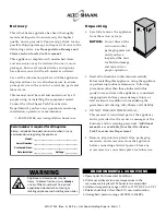
background image

p r i n t e d


i n


u

.

s

.

a

W164 N9221 Water Street  •  P.O. Box 450

Menomonee Falls, Wisconsin 53052-0450 U.S.A.

PHONE:

 262.251.3800  •  800.558.8744 

U.S.A. / CANADA

FAX:

 262.251.7067  •  800.329.8744 

U.S.A. ONLY

www.alto-shaam.com

Consult instructions 

for operation and use.

Hot Food Holding 

Drop-In Wells  

Electric

500-HWI/D4

• InstallatIon
• operatIon
• MaIntenance

Models: 
 100-HW/D4/D6/D443/D643
  100-HWlF/D4/D6
 200-HW/D4/D6/D443/D643
  200-HWlF/D4/D6
 200-HWI/D4/D6/D443/D643
  200-HWIs/D6
  200-HWIlF/D4/D6
 300-HW/D4/D6/D443/D643
  300-HWlF/D4/D6
 300-HWI/D4/D6/D443/D643
  300-HWIs/D6
  300-HWIlF/D4/D6
 400-HW/D4/D6
  400-HWlF/D4/D6
 400-HWI/D4/D6
  400-HWIlF/D4/D6
 500-HW/D4/D6
  500-HWlF/D4/D6
 500-HWI/D4/D6
  500-HWIlF/D4/D6

400-HW/D4

300-HWI/D6

100-HW/D6

MN-37234 (

rev

. 3) • 06/16

200-HWIS/D6

Summary of Contents for 100-HW/D4

Page 1: ...op In Wells Electric 500 HWI D4 Installation Operation Maintenance Models 100 HW D4 D6 D443 D643 100 HWLF D4 D6 200 HW D4 D6 D443 D643 200 HWLF D4 D6 200 HWI D4 D6 D443 D643 200 HWIS D6 200 HWILF D4 D6 300 HW D4 D6 D443 D643 300 HWLF D4 d6 300 HWI D4 D6 D443 D643 300 HWIS D6 300 HWILF D4 D6 400 HW D4 d6 400 HWLF D4 d6 400 HWI D4 D6 400 HWILF D4 D6 500 HW D4 d6 500 HWlf D4 d6 500 HWI D4 D6 500 HWIL...

Page 2: ...19 Undermount Kit Installation 20 Electrical Connection 24 Electrical Specifications 25 Operation Operating Instructions 26 General Holding Guidelines 27 Care and Cleaning Cleaning and Preventative Maintenance 28 Food Safety 30 Service 100 HW 31 200 HW 33 200 HWI 200 HWIS 35 300 HW 38 300 HWI 300 HWIS 40 400 HW 43 400 HWI 45 500 HW 47 500 HWI 49 Wire Diagrams Always refer to the wire diagram s inc...

Page 3: ...an those indicated in this guide to use and clean the appliance is considered inappropriate and may cause damage injury or fatal accidents in addition to invalidating the guarantee and relieving Alto Shaam of all liability DO NOT DISCARD THIS MANUAL This manual is considered part of the appliance and is provided for the owner or manager of the business and for training personnel Additional manuals...

Page 4: ...e Operating instructions and warnings must be read and understood by all operators and users We recommend regular training of your staff to avoid the risk of accident or damage to the unit Operators must also receive regular safety instructions Any trouble shooting guides component views and parts lists included in this manual are for general reference only and are intended for use by qualified an...

Page 5: ...ces or accessories when these are not being moved These items could move or roll on uneven floors and cause property damage or serious injury Be extremely careful when moving appliances because the food trays may contain hot fluids that may spill causing serious injury ALWAYS open the appliance door very slowly Escaping hot vapors or steam can cause serious injury or death additional safety proced...

Page 6: ...evel the appliance from side to side and front to back with the use of a spirit level For appliances installed on a mobile stand it is important that the floor surface be level due to the probability of frequent repositioning NOTICE It is important to apply a food grade silicone underneath the decor flange to seal flange to the countertop WARNING Improper installation alteration adjustment service...

Page 7: ... 41 kg 101 5 lb 46 kg 400 HWILF 96 5 lb 44 kg 108 lb 49 kg 500 HW 85 lb 39 kg 94 5 lb 43 kg 500 HWLF 89 5 lb 41 kg 100 lb 45 kg 500 HWI 107 lb 49 kg 121 lb 55 kg 500 HWILF 115 lb 52 kg 128 5 lb 58 kg Model Max Capacity Max Volume Full Size Pans 12 x 20 x 4 GN 1 1 530 x 325 x 100mm Half Size Pans 12 x 10 x 4 GN 1 2 265 x 325 x 100mm Third Size Pans 12 x 6 x 4 GN 1 3 176 x 325 x 100mm D4 D443 D6 D4 ...

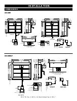
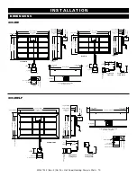
Page 8: ...2mm 5 126mm Conduit when exiting back 4 15 16 125mm 4 102mm 13 5 8 345mm 3 4 18mm FLANGE 6 152mm Optional stainless steel heat shield not factory supplied Ø 1 4 5mm 6 15 16 175mm 6 7 16 163mm 2 1 2 62mm 4 15 16 125mm 27 1 16 686mm 4 3 4 121mm 3 7 16 87mm 20 3 16 512mm WELL 9 3 16 233mm 6 15 16 175mm 5 127mm 5 126mm 3 3 16 81mm 18 5 16 465mm 12 304mm WELL 100 HWLF D4 7 177mm 5 9 16 140mm 4 3 8 111m...

Page 9: ...5 9 16 140mm 1 7 8 46mm 4 1 8 104mm 9 16 14mm FLANGE 6 152mm Conduit when exiting bottom 11 278mm 6 152mm 5 126mm Conduit when exiting back 4 15 16 125mm 4 102mm Ø 3 16 5mm 6 15 16 175mm 6 7 16 163mm 2 1 2 63mm 4 15 16 125mm 1 4 6mm 3 3 16 81mm 31 3 8 796mm 25 635mm WELL 27 1 16 686mm 20 3 16 512mm WELL 3 7 16 87mm 6 15 16 175mm 5 127mm 5 126mm 26 5 8 676mm 2 7 16 60mm FLANGE 2 7 16 60mm FLANGE 7 ...

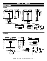
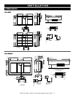
Page 10: ...m 5 8 16mm FLANGE 4 3 8 111mm WELL 7 5 16 185mm 5 9 16 141mm 6 152mm Optional stainless steel heat shield not factory supplied 6 152mm Conduit when exiting bottom 11 278mm 6 152mm 5 126mm Conduit when exiting back 4 15 16 125mm 4 102mm installation 4 15 16 125mm 2 1 2 63mm 10 7 16 264mm 9 15 16 252mm 1 4 6mm Ø 3 16 5mm 200 HWILF D4 7 5 16 185mm 5 9 16 141mm 20 3 16 512mm WELL 22 1 16 559mm 2 1 2 6...

Page 11: ... 1 1 2 38mm 44 3 8 1127mm 20 1 8 512mm WELL 20 1 8 512mm WELL 14 15 16 380mm 11 15 16 304mm WELL 11 15 16 304mm WELL 13 5 8 346mm 6 3 8 162mm WELL 9 5 16 236mm 7 9 16 191mm 4 1 8 104mm 1 13 16 46mm 6 152mm Conduit when exiting bottom 11 278mm 6 152mm 5 126mm Conduit when exiting back 4 15 16 125mm 4 102mm 6 152mm Optional stainless steel heat shield not factory supplied installation D ime nsions 2...

Page 12: ...5 16 125mm 2 1 2 63mm 39 5 8 1007mm 11 16 17mm FLANGE 11 16 17mm FLANGE 6 152mm Optional stainless steel heat shield not factory supplied 6 152mm Conduit when exiting bottom 11 278mm 6 152mm 5 126mm Conduit when exiting back 4 15 16 125mm 4 102mm 3 3 16 81 mm 44 1 4 1123mm 37 7 8 962 mm WELL 27 1 16 686mm 20 3 16 512mm WELL 3 7 16 87mm 5 126mm 6 15 16 175 mm 5 127 mm 6 15 16 175 mm 6 7 16 163 mm 1...

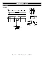
Page 13: ...m FLANGE 27 1 4 691mm WELL 29 1 16 738mm 5 8 15mm FLANGE 7 5 16 185mm 5 9 16 141mm 1 7 8 46mm 4 1 8 104mm 4 3 8 111mm WELL 6 152mm Conduit when exiting bottom 11 278mm 6 152mm 5 126mm Conduit when exiting back 4 15 16 125mm 4 102mm D ime nsions 39 11 16 1007mm 2 5 16 59mm FLANGE 6 152mm Optional stainless steel heat shield not factory supplied 27 1 16 686mm 20 3 16 512mm WELL 3 7 16 87mm 3 1 8 79m...

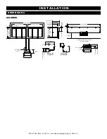
Page 14: ...al stainless steel heat shield not factory supplied 14 15 16 380mm 11 15 16 304mm WELL 1 1 2 38mm 65 5 8 1667mm 20 1 8 512mm WELL 20 1 8 512mm WELL 20 1 8 512mm WELL 13 7 8 353mm 12 305mm 5 126mm WATERTIGHT CONDUIT 6 152mm Conduit when exiting bottom 11 278mm 6 152mm 5 126mm Conduit when exiting back 4 15 16 125mm 4 102mm 13 7 8 353mm 13 3 8 340mm 1 4 6mm Ø 3 16 5mm 4 7 8 125mm 2 1 2 63mm D ime ns...

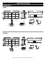
Page 15: ...6 152mm Conduit when exiting bottom 11 278mm 6 152mm 5 126mm Conduit when exiting back 4 15 16 125mm 4 102mm installation D ime nsions 20 3 16 512mm WELL 27 1 16 686mm 3 7 16 87mm 57 5 16 1455mm 50 15 16 1294mm WELL 3 3 16 81mm 5 126mm 10 7 16 264mm 8 1 2 216mm 22 1 16 559mm 20 3 16 512mm WELL 2 1 2 63mm FLANGE 7 5 16 185mm 5 9 16 140mm 4 3 8 111mm WELL 4 1 8 104mm 1 7 8 46mm 52 3 4 1339mm 2 5 16 ...

Page 16: ...Ø 3 16 5mm 6 152mm Conduit when exiting bottom 11 278mm 6 152mm 5 126mm Conduit when exiting back 4 15 16 125mm 4 102mm D ime nsions 52 3 4 1339mm 2 5 16 58mm FLANGE 6 152mm Optional stainless steel heat shield not factory supplied 57 5 16 1455mm 3 1 8 79mm 12 305mm WELL 20 3 16 512mm WELL 27 1 16 686mm 3 7 16 87mm 5 126mm 17 7 16 442mm 15 1 2 394mm 4 1 8 104mm 1 7 8 46mm 7 5 16 185mm 5 9 16 141mm...

Page 17: ...mm 500 HW D4 6 152mm Conduit when exiting bottom 11 278mm 6 152mm 5 126mm Conduit when exiting back 4 15 16 125mm 4 102mm installation D ime nsions 7 5 16 185mm 5 9 16 140mm 4 3 8 111mm WELL 22 1 16 559mm 20 3 16 512mm WELL 2 1 2 63mm FLANGE 4 1 8 104mm 1 7 8 46mm 65 3 4 1670mm 2 5 16 58mm FLANGE 6 152mm Optional stainless steel heat shield not factory supplied 70 7 16 1787mm 64 1625mm WELL 20 3 1...

Page 18: ...upplied 6 152mm Conduit when exiting bottom 11 278mm 6 152mm 5 126mm Conduit when exiting back 4 15 16 125mm 4 102mm D ime nsions 65 3 4 1670mm 2 5 16 58mm FLANGE 6 152mm Optional stainless steel heat shield not factory supplied 70 3 8 1787mm 3 1 8 79mm 12 305mm WELL 20 3 16 512mm WELL 27 1 16 686mm 3 7 16 87mm 20 15 16 531mm 19 483mm 5 126mm 22 1 16 559mm 20 3 16 512mm WELL 2 1 2 63mm FLANGE 4 1 ...

Page 19: ... 3 8 162mm 37 7 8 962mm 27 1 4 691mm 300 HWLF D4 7 5 16 185mm 44 1 4 1123mm 27 1 16 686mm 4 3 8 111mm 37 7 8 962mm 20 3 16 512mm 300 HWLF D6 9 1 8 232mm 44 1 4 1123mm 27 1 16 686mm 6 3 8 162mm 37 7 8 962mm 20 3 16 512mm 300 HWI D4 7 5 16 185mm 40 7 8 1038mm 23 3 16 588mm 4 3 8 111mm 12 304mm 20 3 16 512mm 300 HWI D6 9 1 4 234mm 40 7 8 1038mm 23 3 16 588mm 6 3 8 162mm 12 304mm 20 3 16 512mm 300 HWI...

Page 20: ...x 274mm 300 HW D443 or D643 three full three third size pans 40 x 29 1 2 1016mm x 749mm 4 1 4 x 5 1 4 x 10 13 16 108mm x 133mm x 274mm 300 HWI D4 or D6 three full size pans 300 HWILF D4 or D6 three full size pans 40 x 22 1 2 1016mm x 572mm 4 1 4 x 12 1 4 x 10 13 16 108mm x 311mm x 274mm 300 HWI D443 or D643 three full three third size pans 40 x 29 1 2 1016mm x 749mm 4 1 4 x 12 1 4 x 10 13 16 108mm...

Page 21: ...ere to an unclean surface 3 Remove the knob s from the thermostat s by pulling knob away from control Remove the décor face from the appliance by removing the two 2 screws located to the right and left of the thermostat 4 Making sure TOP etching is at the top route control housing through opening cut in step 1 Secure the décor face housing to the control housing using the screws removed in step 3 ...

Page 22: ...allation U nde rmount kit 5020793 installation option 4 1 SRV 20035 REV 1 Alto Shaam Technical Service 800 558 8744 x6702 servicedept alto shaam com q MIX J B WELD STEEL AND HARDENER AT 1 1 RATIO 2 OZ WILL BE ENOUGH FOR FOUR STUDS 2 of 7 1 2 3 4 BEFORE MIXING AFTER MIXING q SPREAD MIXED EPOXY ON TOP OF BASE PLATE OF STUD THE EPOXY SHOULD BE APPROXIMATELY SAME THICKNESS AS THE BASE PLATE NOTE SCREW...

Page 23: ...S COVER THREADS WITH TAPE TO AVOID GETTING EPOXY ON THEM q CLEAN THE BOTTOM SURFACE OF THE COUNTER THAT THE HOT WELL WILL MOUNT TO INSIDE CUTOUT SURFACE OF COUNTER MUST BE FINISHED SEALED FOR SANITATION PURPOSES A SOLID SURFACE OR METAL COUNTER IS SUGGESTED NOTE CUTOUT DIMENSIONS ARE SHOWN IN THE IMAGE BUT ARE NOT INCLUDED IN THESE INSTRUCTIONS 6 153mm MINIMUM CLEARANCE FROM EACH SIDE OF THE CUTOU...

Page 24: ...BETWEEN THE CLIPS SHOULD BE ABOUT THE WIDTH OF THE HOT WELL q BEND THE WIRE INTO A V 2 3 51 76mm AWAY FROM THE CENTER OF THE HOT WELL FEED THE FREE END UP THROUGH THE OTHER CLIP BEND AND WRAP AS BEFORE q REPEAT STEPS 14 15 FOR THE WIRE ON THE OPPOSITE SIDE WHEN MAKING THE BEND LEAVE ABOUT 6 152mm BETWEEN THE BENDS 13 6 Installation U nde rmount kit 5020793 installation option c o n t i n u e d 4 1...

Page 25: ... 23 SRV 20035 REV 1 Alto Shaam Technical Service 800 558 8744 x6702 servicedept alto shaam com 7 of 7 Installation U nde rmount kit 5020793 installation option c o n t i n u e d SA M PLE U s e t e m p l a t e i n c l u d e d w i t h k i t 5 0 2 0 7 9 3 ...

Page 26: ...tag WARNING To prevent SERIOUS INJURY DEATH or PROPERTY DAMAGE All electrical connections must be made by a qualified and trained service technician in accordance with applicable electrical codes WARNING To prevent SERIOUS INJURY DEATH or PROPERTY DAMAGE All electrical connections must be made by a qualified and trained service technician in accordance with applicable electrical codes This applian...

Page 27: ...D4 D6 200 HWIS D6 120V 10 0 1 2 208V 240V 4 3 5 0 0 9 1 2 230V 5 2 1 2 200 HW D443 D643 200 HWI D443 D643 120V 13 5 1 6 208V 240V 5 8 6 8 1 2 1 6 230V 6 5 1 6 300 HW D4 D6 300 HWLF D4 D6 300 HWI D4 D6 300 HWILF D4 D6 300 HWIS D6 120V 15 0 1 8 208V 240V 6 5 7 5 1 4 1 8 230V 7 8 1 8 300 HW D443 D643 300 HWI D443 D643 120V 20 3 2 4 208V 240V 8 8 10 1 1 8 2 4 230V 10 6 2 4 400 HW D4 D6 400 HWLF D4 D6 ...

Page 28: ...ting 10 If lower settings are used ensure the food has maintained safe food temperatures Lower settings should be tested by user to ensure food has maintained safe food temperatures between 140 and 160 F 60 and 71 C All pan divider bars required must be utilized at all times with the pan configuration chosen Before loading food into the appliance use a pocket type thermometer to make certain all p...

Page 29: ...mostat control between 60 and 200 F 16 to 93 C If the appliance is equipped with vents close the vents for moist holding and open the vents for crisp holding If the appliance is equipped with a thermostat indicating a range of between 1 and 10 use a metal stemmed indicating thermometer to measure the internal temperature of the product s being held Adjust the thermostat setting to achieve the best...

Page 30: ...surfaces Always use the proper cleaning agent at the manufacturer s recommended strength Contact your local cleaning supplier for product recommendations cleanInG MaterIals The cleaning function can usually be accomplished with the proper cleaning agent and a soft clean cloth When more aggressive methods must be employed use a non abrasive scouring pad on difficult areas and make certain to scrub ...

Page 31: ...eaner must be approved for use on food contact areas Remove soil with the use of a plastic scouring pad 7 Rinse surfaces by wiping with a clean cloth or sponge and clean warm water 8 Remove excess water with a sponge and wipe dry with a clean cloth or air dry Leave area open until interior is completely dry Replace pan insert 9 Interior can be wiped with a sanitizing solution after cleaning and ri...

Page 32: ...ersonal hygiene proper handling of raw foods cooking to a safe internal product temperature and the routine monitoring of internal temperatures from receiving through service A controlled holding environment for prepared foods is just one of the important factors involved in the prevention of food borne illnesses Temperature monitoring and control during receiving storage preparation and the servi...

Page 33: ...32 x 1 4 PAN HD 2 11 WS 2768 WASHER 6 LOCK 2 12 NU 23909 NUT HEX INSERT M5 2 Item Part Description Qty 13 BU 34606 BUSHING STRAIGHT STRAIN RELIEF 1 14 BU 3964 BUSHING STRAIGHT STRAIN RELIEF 1 15 SC 22766 SCREW M5 x 0 8 x 10mm PAN 2 17 CD 3232 CORDSET 14 3 SJTOW 125V 1 5014997 CORDSET BS 1363 FERRULE ASSB 1 5016998 CORDSET CH2 16P FERRULE ASSB 1 CD 33840 CORDSET 15A 208 240V 1 CD 3922 CORDSET 16AWG...

Page 34: ...1 1016204 WRAPPER 1 WELL 6 DEEP 4 3 MODEL 1 1016200 WRAPPER 1 WELL 4 DEEP 4 3 MODEL 1 Item Part Description Qty 5 EL 36317 ELEMENT HEATING PAD 1 EL 36860 ELEMENT HEATING PAD 4 3 MODEL 1 RI 27108 RIVET SEALED 8 7 SC 22281 SCREW M5 x 0 8 x 16mm FLAT 6 8 CR 33179 CONNECTOR FLEX NYLON SWEEP 9 NU 23909 NUT HEX INSERT M5 1 10 WS 22301 WASHER M5 SPLIT LOCK 1 11 SC 36973 SCREW PAN PH METRIC M5 1 12 101704...

Page 35: ...M 1 2 4 13 CD 3232 CORDSET 14 3 SJTOW 125V 1 5014997 CORDSET BS 1363 FERRULE ASSB 1 Item Part Description Qty 5016998 CORDSET CH2 16P FERRULE ASSB 1 CD 33840 CORDSET 15A 208 240V 1 CD 3922 CORDSET 16AWG 3 C INT L HARM 1 14 SC 22766 SCREW M5 x 0 8 x 10mm PAN 2 15 SC 22500 SCREW 6 32 X 1 4 PAN HD 2 16 SC 22271 SCREW M4 x 0 7 x 6mm PAN 4 17 NU 23909 NUT HEX INSERT M5 2 18 WS 2768 WASHER 6 LOCK 2 19 P...

Page 36: ...ULATION 1 6 1015828 WRAPPER 2 WELL 6 DP 1 1016194 WRAPPER 2 WELL 4 DP 1 Item Part Description Qty 1017333 WRAPPER 2 WELL 6 DP 4 3 MODEL 1 1017334 WRAPPER 2 WELL 4 DP 4 3 MODEL 1 7 1016034 BOX CONNECTION 1 8 BU 34606 BUSHING STRAIGHT STRAIN RELIEF 1 RI 27108 RIVET SEALED 8 10 SC 22281 SCREW M5 x 0 8 x 16mm FLAT 8 11 WS 22301 WASHER M5 SPLIT LOCK 1 12 NU 23909 NUT HEX INSERT M5 1 13 SC 36973 SCREW P...

Page 37: ...36424 KNOB T STAT CONTROL 2 13 SC 22500 SCREW 6 32 x 1 4 PAN HEAD 4 Item Part Description Qty 14 WS 2768 WASHER 6 LOCKING SS 4 15 TU 33178 CONDUIT FLEX LIQUID TIGHT 1 16 5014997 CORDSET BS 1363 FERRULE ASSEMBLY 1 5016998 CORDSET CH2 16P FERRULE ASSEMBLY 1 CD 33840 CORDSET 15A 208 240V 1 CD 3922 CORDSET 16AWG 3 C INT L HARM 1 CD 3232 CORDSET 14 3 SJTOW 125V 1 17 1017288 PLATE FACE 1 18 NU 23909 NUT...

Page 38: ...T FOIL HEATING PAD 2 EL 36860 ELEMENT HEATING PAD 810W 2 4 SC 22281 SCREW M5 x 0 8 x 16mm FLAT 6 5 1016034 BOX CONNECTION 1 Item Part Description Qty 6 BU 34606 BUSHING STRAIGHT STRAIN RELIEF 1 7 1017049 BRACKET STANDOFF 230V ONLY 4 RI 27108 RIVET SEALED 12 IN 24588 INSULATION 1 10 9 8 11318 DIVIDER PAN SHORT 4 11 1015828 WRAPPER 2 WELL 6 DEEP 1 1016194 WRAPPER 2 WELL 4 DEEP 1 1017333 WRAPPER 2 WE...

Page 39: ...ELEMENT FOIL HEATING PAD 2 4 5019797 CONNECTION BOX ASSEMBLY 1 5 Item Part Description Qty 6 1018725 INSULATION WELL OUTSIDE 1 1018719 INSULATION 11 875 x 6 38 1 7 11318 PAN DIVIDER SHORT 4 8 BU 34606 BUSHING STRAIGHT STRAIN RELIEF 1 9 SC 22281 SCREW M5 x 0 8 x 16mm FLAT 10 10 RI 27108 RIVET SEALED 12 11 RI 2097 RIVET 42 STAINLESS 13 1 1 Item Part Description Part numbers and drawings are subject ...

Page 40: ...L 1 8 1017287 PLATE FACE 1 9 PG 35411 PLUG 1 4 HOLE 1 10 RL 34279 RELAY 120V 1 Item Part Description Qty 11 NU 22285 NUT M3 0 5 HEX NUT 2 12 SC 22266 SCREW M3 x 0 5 x 6mm PAN 2 13 KN 36424 KNOB T STAT CONTROL 1 14 LI 37215 LIGHT INDICATOR 1 15 PE 36566 PANEL OVERLAY 1 16 WS 2768 WASHER 6 LOCK 2 17 SC 22500 SCREW 6 32 x 1 4 PAN 2 18 SC 22766 SCREW M5 x 0 8 x 10mm PAN 2 19 SC 22926 SCREW M5 x 0 8 x ...

Page 41: ...24588 INSULATION 1 RI 2097 RIVET 42 STAINLESS 10 Item Part Description Qty 7 1015670 WRAPPER 3 WELL 6 DEEP 1 1016195 WRAPPER 3 WELL 4 DEEP 1 1016205 WRAPPER 3 WELL 6 DEEP 4 3 MODEL 1 1016207 WRAPPER 3 WELL 4 DEEP 4 3 MODEL 1 8 1016034 BOX CONNECTION 1 9 BU 34606 BUSHING STRAIGHT STRAIN RELIEF 1 10 WS 22301 WASHER M5 SPLIT LOCK 1 11 SC 36973 SCREW PAN PH METRIC M5 1 12 SC 22281 SCREW M5 x 0 8 x 16m...

Page 42: ...ET 15A 208 240V 1 CD 3922 CORDSET 16AWG 3 C INT L HARM 1 8 WS 2768 WASHER 6 LOCK SS 6 Item Part Description Qty 9 KN 36424 KNOB T STAT CONTROL 3 10 LI 37215 LIGHT INDICATOR 3 11 SC 22766 SCREW M5 x 0 8 x 10mm PAN 2 12 NU 36234 NUT M5 KEPS 2 13 PE 36566 PANEL OVERLAY CONTROL 3 15 SC 22500 SCREW 6 32 x 1 4 PAN HEAD 6 16 TA 24637 TAPE VHB FOAM 1 2 x 12 9 1 17 TU 33178 CONDUIT FLEX LIQUID TIGHT 1 18 W...

Page 43: ...ATING PAD 600W 3 EL 36860 ELEMENT FOIL HEATING PAD 810W 3 IN 24588 INSULATION 8 DENSITY 39 x 22 x 1 1 5 1015670 WRAPPER 3 WELL 6 DEEP 1 Item Part Description Qty 1016195 WRAPPER 3 WELL 4 DEEP 1 1016205 WRAPPER 3 WELL 6 DEEP 4 3 MODEL 1016207 WRAPPER 3 WELL 4 DEEP 4 3 MODEL 6 1017049 BRACKET STANDOFF 4 RI 2097 RIVET 42 STAINLESS 9 8 SC 22281 SCREW M5 x 0 8 x 16mm FLAT 8 9 SC 22926 SCREW M5 x 0 8 x ...

Page 44: ...L SLIMLINE 3 EL 36317 ELEMENT FOIL HEATING PAD 3 4 5019797 CONNECTION BOX ASSEMBLY 1 Item Part Description 5 1018720 INSULATION WELL OUTSIDE 1 6 1018719 INSULATION 11 875 x 6 38 2 7 11318 PAN DIVIDER SHORT 6 8 BU 34606 BUSHING STRAIGHT STRAIN RELIEF 1 9 SC 22281 SCREW M5 x 0 8 x 16mm FLAT 14 10 RI 38125 RIVET SEALED 125 12 11 RI 2097 RIVET 42 STAINLESS 13 1 1 Qty Part numbers and drawings are subj...

Page 45: ...EF 230V 1 9 BU 34606 BUSHING STRAIN RELIEF 120V 208 240V 1 10 CR 34646 CONNECTOR 5 CONDUCTOR 4 Item Part Description Qty 11 KN 36424 KNOB T STAT CONTROL 2 12 NU 23909 NUT HEX INSERT M5 2 13 NU 36234 NUT M5 KEPS 2 14 PE 36566 PANEL OVERLAY 2 15 PG 35411 PLUG 1 4 HOLE 3 16 SC 22766 SCREW M5 x 0 8 x 10mm PAN 2 17 SC 22271 SCREW M4 x 0 7 x 6mm PAN 4 18 LI 37215 LIGHT INDICATOR 2 19 SC 22500 SCREW 6 32...

Page 46: ...WRAPPER 4 WELL 6 DEEP 1 1016168 WRAPPER 4 WELL 4 DEEP 1 Item Part Description Qty 7 1016034 BOX CONNECTION 1 RI 2097 RIVET 42 STAINLESS 10 9 WS 22301 WASHER M5 SPLIT LOCK 1 10 NU 23909 NUT HEX INSERT M5 1 11 SC 36973 SCREW PAN PH METRIC M5 1 12 BU 34606 BUSHING STRAIGHT STRAIN RELIEF 1 13 1017049 BRACKET STANDOFF 230V ONLY 4 14 RI 27108 RIVET SEALED 8 15 SC 22281 SCREW M5 wx 0 8 x 16mm FLAT 12 5 8...

Page 47: ...R 34646 CONNECTOR 5 CONDUCTOR 12 9 KN 36424 KNOB T STAT CONTROL 4 10 LI 37215 LIGHT INDICATOR 4 Item Part Description Qty 11 SC 22766 SCREW M5 x 0 8 x 10mm PAN 2 12 NU 36234 NUT M5 KEPS 2 13 PE 36566 PANEL OVERLAY 4 14 PG 35411 PLUG 1 4 HOLE 2 15 SC 22500 SCREW 6 32 x 1 4 PAN HD 8 16 TA 24637 TAPE VHB FOAM 1 2 WIDE 1 17 TU 33178 CONDUIT FLEX LIQUID TIGHT 2 19 WS 2768 WASHER 6 LOCK 8 20 1017290 PLA...

Page 48: ...6 5017611 WELDMENT D6 STD FLANGE 1 5017616 WELDMENT D4 STD FLANGE 1 5017711 WELDMENT D4 WIDE FLANGE 1 Item Part Description Qty 5017706 WELDMENT D6 WIDE FLANGE 1 7 BU 34606 BUSHING STRAIGHT STRAIN RELIEF EL 36317 ELEMENT FOIL HEATING PAD 4 IN 24588 INSULATION 1 10 NU 36234 NUT M5 KEPS 2 11 RI 2097 RIVET 42 STAINLESS 10 12 RI 27108 RIVET SEALED 12 13 WS 22295 WASHER FLAT M5 S S 8 9 2 1 5 6 10 13 12...

Page 49: ...TOR 4 9 TA 24637 TAPE VHB FOAM 1 2 WIDE 4 10 SC 22766 SCREW M5 x 0 8 x 10mm PAN 2 Item Par t Description Qty 11 KN 36424 KNOB T STAT CONTROL 2 13 1015724 SHELL CONTROL POD 2 KNOB 1 14 BU 33505 BUSHING STRAIN RELIEF 230V 1 15 BU 34606 BUSHING STRAIN RELIEF 120V 208 240V 1 16 CL 37245 CLIP LIGHT MOUNTING 2 17 LI 37215 LIGHT INDICATOR 2 18 NU 23909 NUT HEX INSERT M5 2 19 NU 36234 NUT M5 KEPS 2 20 PE ...

Page 50: ...1 5018549 WELL D6 WIDE FLANGE 1 5 EL 37233 ELEMENT HEATING PAD 2 6 1015717 WRAPPER 5 WELL 6 DEEP 1 Item Part Description Qty 1016196 WRAPPER 5 WELL 4 DEEP 1 7 1016034 BOX CONNECTION 1 8 WS 22301 WASHER M5 SPLIT LOCK 1 9 NU 23909 NUT HEX INSERT M5 1 10 SC 36973 SCREW PAN PH METRIC M5 1 11 RI 2097 RIVET 42 STAINLESS 10 15 1017049 BRACKET STANDOFF 230V ONLY 4 10 8 11 9 7 15 5 1 6 3 4 2 10 8 11 9 7 15...

Page 51: ...6 SCREW M5 x 0 8 x 10mm PAN 1 9 SC 22271 SCREW M4 x 0 7 x 6mm PAN 4 10 CR 34646 CONNECTOR 5 CONDUCTOR 14 Item Part Description Qty 11 PG 35411 PLUG 1 4 HOLE 3 12 CC 36859 CONTROL 5 13 1017291 PLATE FACE 1 14 TA 24637 TAPE VHB FOAM 1 2 WIDE 1 15 1015808 BOX REMOTE DECOR FACE 5 KNOB 1 16 PE 36566 PANEL OVERLAY 5 17 CL 37245 CLIP LIGHT MOUNTING 5 18 WS 2768 WASHER 6 LOCK 10 19 LI 37215 LIGHT INDICATO...

Page 52: ... 33 4 x 78 1 5 1015717 WRAPPER 5 WELL 6 DEEP 1 1016196 WRAPPER 5 WELL 4 DEEP 1 6 1016034 BOX CONNECTION 1 Item Part Description Qty RI 2097 RIVET 42 STAINLESS 10 8 7 BU 34606 BUSHING STRAIN RELIEF 2 9 WS 22301 WASHER M5 SPLIT LOCK 1 10 NU 23909 NUT HEX INSERT M5 1 11 SC 36973 SCREW PAN PH METRIC M5 1 12 RI 27108 RIVET SEALED 12 13 SC 22281 SCREW M5 x 0 8 x 16mm FLAT 8 14 1017049 BRACKET STANDOFF 2...

Page 53: ...ev 3 06 16 Hot Food Holding Drop In Well 51 Refer to wire diagram sent with appliance for most current version Wire Diagrams Always refer to the wire diagram s included with the appliance for most current version ...

Page 54: ...MN 37234 Rev 3 06 16 Hot Food Holding Drop In Well 52 Refer to wire diagram sent with appliance for most current version ...

Page 55: ...nce or fifteen 15 months from the shipping date whichever occurs first The labor warranty period is one 1 year from the date of installation or fifteen 15 months from the shipping date whichever occurs first Alto Shaam will bear normal labor charges performed during standard business hours excluding overtime holiday rates or any additional fees To be valid a warranty claim must be asserted during ...

Reviews: