background image

111027

1

 -

Technical Bulletin

111027 Rev.*

SIGMA DATA 7200 WRITE MAGNETIC HEAD REPLACEMENT
INSTRUCTIONS

Tools Required:

No.2 Phillips screwdriver (long length)
Wrist strap (or similar device) for ESD grounding

To Prepare the Printer for Maintenance:

1.


Verify that all replacement parts and tools are present.

2.


Turn off the power switch, unplug the AC power cord, and disconnect all communication and
interface cables.

3.


(1) Unlock and open the Lower Right Side
Cover then (2) open the Upper Right Side
Cover completely, until it rest on the
Service Cover (Fig.1).

4.


Remove the Service Cover by removing
the two M3 Phillips screws holding the
Service Cover to the upper frame of the
printer (Fig. 2).

Fig. 1

Fig. 2

5.


Loosen or remove two M3 Phillips screws, located on the topside
of the Back Panel, and remove the Back Panel from the printer.


Fig. 3

To Replace the Write Magnetic Head Assembly:

IMPORTANT: 

Properly ground yourself using an ESD wrist strap (or similar device) to prevent static

discharge damage to the electronics.

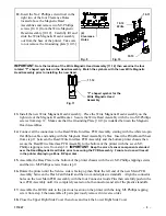
6.


Remove the four M3 Phillips tapping
screws [4.1] from the Flash Card
Assembly.  Remove three M3 Phillips
tapping screws [4.2] located in the corners
of the Flash Card Shield then disconnect
the Flash Card Assembly from the Main
PCB Assembly.

                       
Fig. 4

4.1

4.1

4.1

4.1

4.2

4.2

4.2

Flash Card
Assembly

Flash Card Shield

Summary of Contents for SIGMA DATA 7200

Page 1: ... the Service Cover by removing the two M3 Phillips screws holding the Service Cover to the upper frame of the printer Fig 2 Fig 1 Fig 2 5 Loosen or remove two M3 Phillips screws located on the topside of the Back Panel and remove the Back Panel from the printer Fig 3 To Replace the Write Magnetic Head Assembly IMPORTANT Properly ground yourself using an ESD wrist strap or similar device to prevent...

Page 2: ...hift the Read Write Interface PCB Assembly to the right then gently pull the left end of the PCB Assembly out from the base of the printer IMPORTANT Notice how the arm of the sensor component located on the backside and to the right end of the PCB Assembly extends over the Read Magnetic Assembly Cable when the PCB Assembly is pulled out Fig 7 11 Disconnect all the cables from the connectors on the...

Page 3: ...m step 11 between the Read Write Interface PCB Assembly and the bottom printer chassis then secure the Read Write Interface PCB Assembly to the bottom of the printer with the seven M3 Phillips tapping screws from step 10 IMPORTANT Keep the arm of sensor component extended over the Read Magnetic Head Cable prior to securing the PCB Assembly Failure to do so will result in the printer displaying a Z...

Page 4: ...ayed Then press the Enter button Write Stock 3 Use the UP Down arrow button to select the path where the printed sample will be pulled from then press the ENTER button F 4 The printer will print a blank coupon But information will be encoded on the magnetic stripe 5 Press the Up or Down arrow button until Magstripe Dump test is displayed Then press the Enter button Magstripe Dump Magstripe Dump 6 ...

Reviews: