

[Type text]
2761-255-00
1
1/2013
Specifications Information and Repair Parts Manual
2761-98 thru 282D-98 & 2821-98 thru 282M-98
x
Please read and save this Repair Parts Manual. Read this manual and the General Operating Instructions carefully before attempting to assemble,
install, operate or maintain the product described. Protect yourself and others by observing all safety information. The Safety Instructions are contained
in the General Operating Instructions. Failure to comply with the safety instructions accompanying this product could result in personal injury and/or
property damage! Retain instructions for future reference
.
AMT reserves the right to discontinue any model or change specifications at any time without
incurring any obligation.
©2013 American Machine & Tool Co., Inc. of PA, A Subsidiary of The Gorman-Rupp Company, All Rights Reserved.
Periodic maintenance and inspection is required on all pumps to ensure proper operation. Unit must be clear of debris and sediment. Inspect for leaks and loose bolts. Failure
to do so voids warranty.
Self-Priming Centrifugal Pumps
High Volume Dewatering Stainless Steel Models
Refer to pump manual 1808-634-00 for General Operating and Safety Instructions.
DESCRIPTION
These centrifugal pumps are self-priming (to 20 ft. lift) units designed for high volume liquid transfer, irrigation, dewatering, lawn sprinkling, etc. These
pumps can also accommodate semi-solids (up to 3/8" dia.), sediment laden liquids, and liquids with entrained air or gases. Units are constructed of 316
stainless steel and include Viton
®
elastomers. They are direct coupled to NEMA 56J frame, 3450 RPM motors which require field wiring, no controls are
supplied. Each pump is equipped with a flapper valve to shorten re-prime time. Handles liquids from 40º to 200º F (4º to 93º C). For use with
nonflammable, non-abrasive liquids compatible with pump component materials.
MAINTENANCE
Make certain that unit is disconnected from power source before
attempting to service or remove any components!
NOTE:
The pump casing should be removed and inspected
periodically to insure that any foreign material is not clogging internal
pump parts. This unit is equipped with a dual volute pump casing. One
of the volutes runs 180°, all the way from the side opposite the
discharge into the discharge through a completely enclosed
passageway. If foreign material clogs this area, it can be dislodged by
using a wire or long spring.
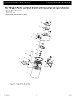
MECHANICAL SEAL REPLACEMENT
Refer to Figures 1 and 2
IMPORTANT:
Always replace both seal seat (Ref. No. 8) and seal
head (Ref. No. 9) to ensure proper mating of components!
Recommend replacing casing seal (Ref. No.7) if wear or damage is
present.
1.
Unthread fasteners (Ref. No. 6) and remove casing (Ref. No.
13) and casing seal (Ref. No. 7) from adapter (Ref. No. 5)
2.
Unscrew impeller fastener (Ref. No. 12) and impeller (Ref.
No. 11) separately by turning each counterclockwise.
NOTE:
Most motors use an open end 7/16" wrench across flats on
rear of motor shaft (remove bearing cap for access) to prevent shaft
from turning. Other motor shafts have a screwdriver slot instead of
flats.
3.
Unscrew fasteners (Ref. Nos. 4 & 17) and remove adapter,
foot (Ref. No. 18) and handle (Ref. No. 3) from motor (Ref.
No. 1) mounting face. Seal head will come loose at this time.
4.
Push seal seat from adapter recess with a screwdriver.
5.
Clean adapter recess before inserting new seal seat.
6.
Carefully wipe polished surface of new seal seat with a clean
cloth.
7.
Wet rubber portion of seal seat with a light coating of soapy
water.
8.
Press new seal seat squarely into cavity in adapter. If seal
seat does not press squarely into cavity, it can be adjusted in
place by pushing on it with a piece of pipe. Always use a
piece of cardboard between pipe and seal seat to avoid
scratching seal seat. (This is a lapped surface and must be
handled very carefully.)
9.
After seal seat is in place, ensure that it is clean and has not
been marred.
10.
Using a clean cloth, wipe shaft and make certain that it is
perfectly clean.
11.
Secure adapter, foot, and handle on motor mounting face.
Carefully guide motor shaft through seal seat.
12.
Apply a light coating of soapy water to inside rubber portion
of seal head and slide onto shaft (with sealing face first) so
that rubber portion is just up over shaft shoulder.
Do not touch or wipe polished face of seal head.
13.
Replace any impeller shims (Ref. No. 10) which may have
been removed in disassembly. (See "Shim Adjustment"
below).
14.
Screw impeller back into place, tightening until it is against
shaft shoulder.
15.
Replace impeller nut and tighten until snug.
16.
Remount casing and casing seal on adapter.
SHIM ADJUSTMENT
When installing a replacement impeller (Ref. No. 11) or motor (Ref.
No. 1), it may be necessary to adjust number of shims (Ref. No. 10) to
ensure proper running clearance between impeller and casing.
Proceed as follows:
NOTE:
A proper running clearance is less than 0.010".
1.
For impeller replacement, add one 0.010"shim in addition to
those removed originally.
2.
For motor replacement, add two 0.010" shims in addition to
those removed during disassembly.
3.
Reassemble the pump as described in steps 15, 16 & 17.
IMPORTANT
: Be sure that the casing is snugly in place and check
shaft to make sure it is turning freely (use screwdriver slot in motor to
turn shaft). If it turns freely, check to ensure that adapter and casing
are fitted tight together. If they are not, tighten fasteners (Ref. Nos. 4, 6
and 18) and recheck shaft for free turning. Tighten carefully, turning
shaft while tightening so that motor bearings are not damaged in the
event that too many shims were installed. If shaft seizes before
fasteners are completely tight, disassemble pump and remove one
shim and repeat reassembly.
FLAPPER VALVE ASSEMBLY REPLACEMENT
Remove bolts (Ref. No. 20) and suction plate (Ref. No. 16). Replace
flapper valve assembly (Ref. No. 15). Remount suction plate and bolts;
tighten bolts evenly to ensure proper seal.
Summary of Contents for 2827-98
Page 6: ...Specifications Information and Repair Parts Manual NOTES ...
Page 7: ......
Page 8: ...www amtpump com ...


