background image

[ IMPORTANT ]

▶ Please read the manual carefully and keep it in mind before using this machine

▶ Put this manual within touch of your reference in anytime.

※ QR(SUPPROT) - Leaflets, manuals, solution(error code,trouble shooting decument, watch&solve)

PRODUCT INFO

PART INFO

SUPPORT INFO

NEW PRODUCT INFO

ISSUE DATE:Mar. 23, 2022

Ver 1.0_

Ver 1.0_

INT

INT

Summary of Contents for AVENGERS

Page 1: ...ore using this machine Put this manual within touch of your reference in anytime QR SUPPROT Leaflets manuals solution error code trouble shooting decument watch solve PRODUCT INFO PART INFO SUPPORT IN...

Page 2: ...ult Replacing the machine parts inspecting and maintaining the machines and troubleshooting must be assigned only to a qualified in shop maintenance person or industry specialist This booklet gives in...

Page 3: ...a e h t c e r i D c t e s e c n a t s b u s e l b a m m a l f s u o d r a z a H t l u s e r y a m n o i t c n u f l a m r o t n e d i c c a n a e s i w r e h t O r o s l a c i m e h c g n i d l o h s...

Page 4: ...e h t f I r u o y k s a d n a y l e t a i d e m m i e n i h c a m e h t g n i s u p o t s s t r a p e h t e c a l p e r o t r e l a e d t s e r a e n h c t i w s r e w o p n i a m e h t F F O n r u T...

Page 5: ...n u d n a e h t g n i n a e l c r o g n i t c e p s n i e r o f e b e l c a t p e c e r e n i h c a m f o s t r a p e s u o t e r u s e b s t r a p g n i c a l p e r n e h W s t r a p e s u r e v e N...

Page 6: ...maintenance des machines et le d pannage doit tre attribu qu une personne de maintenance qualifi e en atelier ou sp cialiste de l industrie Cette brochure donne des instructions que les emplois danger...

Page 7: ...imm diatement d utiliser la machine et demandez votre revendeur le plus proche de remplacer les pi ces 1 Mettez l interrupteur principal sur ARR T 2 D branchez le c ble d alimentation de la prise 3 Co...

Page 8: ...tisation et du chauffage etc Des substances inflammables dangereuses Sinon un accident ou un dysfonctionnement Ne pas placer les r cipients contenant des produits chimiques ou de l eau sur ou pr s de...

Page 9: ...avant d inspecter ou de nettoyer la machine Lors du remplacement des pi ces veillez utiliser une partie des sp cifications correctes Ne jamais utiliser de pi ces autres que celles sp cifi es L ouvertu...

Page 10: ...TOCKEN CARD SETTING p SETUP SETTINGS 1 PROGRAM SETTING p 2 CLEAR MODE p 3 BOOKKEEPING DATA p 4 FACTORY SETTING p 5 TEST MODE p 6 PLAYFIELD SETUP p 7 GAME MODE p MAINTENANCE p SOLUTION 1 ERROR CODE p 2...

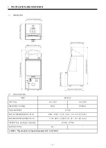
Page 11: ...bolt product AC 120 230V 210 W CONSUMPTION DETAILS ETL VOLTAGE AC 120V AC 230V CERTIFICATION 1 ITEM INSTALL DIMENSION W D H PACKING DIMENSION W D H WEIGHT kg packing weight kg FREQUENCY RANGE 60 Hz 50...

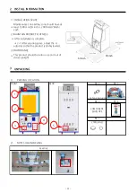
Page 12: ...3 STICKER LOCATION 8 9 1 2 3 Certification Label 4 5 6 7 3...

Page 13: ...inch each This product should be indoor use and out of direct sunlight MAINTAIN PRODUCT FLATNESS After installation is complete 2 1 After securing space adjust the 4 adjuster so that the product is st...

Page 14: ...E 1 3 12 SCREW TH_NI M4x8L 16 18 MANUAL MEDAL 1 10 no no PART NAME Q TY SPARE AC POWER CORD 8 11 KEY 7001 2 BALL 1 4 2 16 CARD 1 box 4 14 CARD HEAVY PUSH BKT 1 6 SCREW M4x20L 6 15 COIN SELECTOR COVER...

Page 15: ...S B_DECO MAIN COVER B B_DECO MAIN ASS Y 1 no This product is a free bolt product AC 120 230V 7 ASSEMBLE 1 TH_NI 1 TH_NI ASSEMBLE TH_NI 2 Q ty 4 ITEM SPEAKER BOX DECO COVER L SPEAKER BOX DECO COVER R B...

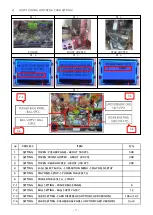
Page 16: ...TION MENU PLAYFIELD SETUP PLAYFIELD SETUP PUSHER TABLE SET A PUSHER TABLE SET A START BALL SETTING PUSHER BASE PANEL BALL SETTING BALL SUPPLY ASS Y CARD SETTING CARD DISPENSOR OPTION CARD VERSION CARD...

Page 17: ...6 PLAYFIELD SETUP PLAYFIELD SETUP GAME MODE 1 PROGRAM SETTINGS SETUP MODE 2 CLEAR MODE DELETE MODE 3 BOOKKEEPING DATA VIEW GAME DATA EXIT TO OPERATION OPTIONS 7 4 FACTORY SETTING TEST MODE TESET MODE...

Page 18: ...TN 5 TN 1 TN 3 TN 1 TN 3 DEFAULT INT TI 3 TN 1 TN 3 TN 1 TN 5 TN 3 TN 1 TI 10 TN 1 TN 3 TN 1 TN 5 TN 1 TN 3 TN 1 TI 3 TN 1 TN 1 TN 5 TN 1 TN 3 TN 1 TI 10 TN 1 TN 3 TI 10 TN 1 TN 3 TN 5 TN 1 14 42 21 6...

Page 19: ...nd and setting volume LAMP SPEED Lamp wheel movement speed LAMP REVERSE Lamp wheel forward reverse rotation setting X X X X CHECKER BONUS Setting bonus tickets when making goal into main checker at ma...

Page 20: ...cker pass BIG WHEEL WIN REEL 4 0 REEL 5 0 REEL 6 0 Number of BIG WHEEL wins Number of card dispensing BIG WHEEL WIN REEL 7 0 REEL 8 0 TOTAL 0 Number of BIG WHEEL wins BONUS COIN SHOT 0 6 BALL COLLECTI...

Page 21: ...y Conveyer test PLAYS FND Display of sensor stauts Ticket dispenser test When performed it automatically stops after discharging 3 tickets if there are tickets PLAYS FND Display of sensor status and q...

Page 22: ...hopper 2 Select the relevant mode 3 The wheel spins and stops and then automatically fires 1 000 medals 4 When all 1 000 medals are fired it automatically stopped and pusher table medal setting is co...

Page 23: ...st be turned on after 10 seconds 2 When installing the device Connect the device with a ground outlet to which fg is connected 3 Main board management Dust removal on the main board will be carried ou...

Page 24: ...41 PUSHER ERROR Pusher motor problem or pusher encoder problem E 51 WHEEL ERROR Wheel motor problem encoder problem E 52 BIG WHEEL ERROR E 72 32 E 73 BALL IN SENSOR Ball in sensor 33 No tickets or tic...

Page 25: ...tected Sensor _ Non Detected sensor 0 2 Check connection of sensor connector P3 3 Check assembly status of sensor Check position of sensor bracket Center P4 4 Check the dc voltage SENSOR PCB PIN 1 ove...

Page 26: ...ST MODE PUSHER MOTOR TEST SELECT BUTTON SHOOTING button Sensor operation status Detected Sensor _ Non Detected sensor 0 1 Check if tokens cards balls side token are jamming the pusher plate P1 2 Check...

Page 27: ...n of motor connector P1 3 Check assembly status of belt and motor P2 4 Check the dc voltage MAIN PCB CN20 PIN 1 Over 11V PIN 3 Below 0 5V PIN 6 GND PIN 2 Operation state over 4 5V Non operation state...

Page 28: ...utton SHOOTING button Sensor operation status Detected Sensor flicker _ Non Detected sensor 0 2 Check connection of sensor connector P4 3 Check assembly status of sensor Check position of sensor brack...

Page 29: ...PER PCB 8 Check the dc voltage MAIN PCB CN10 A PIN 1 Over 23V A PIN 6 Over 4 5V A PIN 10 GND 9 Replace MAIN PCB SOLUTION FRONT HOPPER SENSOR ERROR E 61 1 HOW TO TEST TEST MODE FRONT HOPPER TEST SELECT...

Page 30: ...AIN PCB SOLUTION REAR HOPPER SENSOR ERROR E 62 1 HOW TO TEST TEST MODE REAR HOPPER TEST SELECT button SHOOTING button PLAY FND 3rd digit confirms quantity change reduced sequentially when sensor is de...

Page 31: ...Y TEST SELECT button SHOOTING button Third digit of the PLAY FND Detected Sensor flicker _ Non Detected sensor 0 2 Check connection of sensor connector P4 3 Check assembly status of sensor Check posit...

Page 32: ...is recognized it checks whether it was pressed normally and returns to its original state if not recognized P 2 4 Check the dc voltage SWITCH NO PIN over 4 5V ball is not mounting Below 0 5V ball is...

Page 33: ...mber 2 Check connection of sensor connector CHECK 1 3 Check assembly status of sensor CHECK 2 4 Check the dc voltage SENSOR PCB PIN 1 over 4 5V PIN 2 below 0 5V PIN 4 GND PIN 3 Detected Sensor over 4...

Page 34: ...check Detected Sensor _ Non Detected sensor 0 2 Check internal JAM by foreign material card token P1 3 SENSOR PCB wiring connection and connector connection status check P2 4 Check the sensor assembly...

Page 35: ...nection and connector connection status check P2 4 Check the sensor assembly status P3 5 voltage check SENSOR PCB PIN 1 more than 4 5V PIN 2 less than 0 5V PIN 4 GND PIN 3 more than 4 5V when detected...

Page 36: ...2 Check the sensor status in the first digit of PLAY FND When detected _ When not detected 0 3 Check internal JAM by TOKEN CARD BALL P1 4 SENSOR PCB wiring connection and connector connection status...

Page 37: ...tton SHOOTING button When detected _ When not detected 0 2 SENSOR PCB wiring connection and connector connection status check P1 3 Check the sensor assembly status and check the sensor bracket hole an...

Page 38: ...check CHECK 2 4 Check the sensor assembly status check the presence of foreign substances inside CHECK 1 5 voltage check SENSOR PCB PIN 1 4 5V or more PIN 4 GND PIN 2 less than 0 5V when detected more...

Page 39: ...EXPLODED VIEW FULL DESCRIPTION 8 1 2 3 4 5 6 7 8 9 10 11 12 13 14 15 16 17 18 19 20 22 21 23 24 25 26 27 35 30 29 31 32 33 34 34 28 30...

Page 40: ...PART 1 p48 15 BIG BALL ELEVATOR PART 1 p49 16 BIG BALL INLET GUIDE RAIL PART 1 p50 17 TARGET WHEEL PART 1 p50 18 SLOT WHEEL PART 1 p51 19 TARGET WHEEL DECO COVER PART 1 p51 20 TOKEN BRIDGE PART 1 p52...

Page 41: ...ILLBOARD CABINET SIDE DECO ACRYL L PART NAME SPEC Q TY CODE NO 1 BILLBOARD DECO MAIN COVER B PET 2T AAV10ACP004 PET 2T 1 PART NAME AAV10ACP003 CODE NO NO 1 AAV10ACP002 4 LED BAR PCB ASS Y 460 MM 2 AZZ...

Page 42: ...2 6 NOISE FILTER RNS 2010 1 MELE0NOI009 NO PART NAME SPEC Q TY CODE NO 4 POWER SMPS LRS75 5 1 MELE0SMP094 5 TERMINAL BLOCK 250V 10P UL_CE 1 MELE0TEB003 2 POWER SMPS RSP 320 24 1 MELE0SMP100 3 POWER SM...

Page 43: ...GHT 1 AFND0PCB007 NO PART NAME SPEC Q TY CODE NO 1 SENSOR_R PCB ASS Y 1 MEIF0PAR014 6 PUSH BUTTON SWITCH DS 412R 2 MELE0PUS006 7 SETUP PANEL BKT PET COVER 1 MSBP0ACR040 4 ROCKER SWITCH R595KDF 1 MELE0...

Page 44: ...6ZZ 1 MSBP0PRO002 NO PART NAME SPEC Q TY CODE NO 1 SIDE PAYOUT GUIDE MOLD 2 MDCC0PLA010 3 PHOTO INT1 ANGLE PCB ASS Y ANGLE TYPE 1 AZZZ0PCB103 4 MOTOR KGV 2 0350 KB3640S1 1 MZZZ0MOT152 1 MOVING PUSHER...

Page 45: ...CR043 PC 3T NO PART NAME SPEC Q TY CODE NO 3 LED PCB ASS Y ANGLE TYPE 1 AMUM0PCB005 1 WHEEL COIN INLET RAIL ACRYL PC 1T 1 MAV20ACR007 2 CHUTE SENSOR PCB ASS Y IR SENSOR 2 ASAW0PCB001 NO PART NAME SPEC...

Page 46: ...0PCB103 SPEC Q TY CODE NO 4 MOTOR KGV2 0200 3657U1 1 MZZZ0MOT161 5 MICRO SWITCH CNR 05H 03 ZIPPY 2 MELE0MIC002 2 BIG BALL ELEVATOR BELT PVC1 4Tx50Wx954 2L 1 MZZZ0BEL047 3 COUPLING CR050 1 AZZZ0COP002...

Page 47: ...RGET WHEEL BASE ACRYL ACRYL 5T 1 MAV20ACR008 2 TARGET COVER ACRYL PC 1T 10 AAV20ACP022 3 TARGET WHEEL MOTOR TIMMING BELT 148XL 1 MSAW0ZZZ004 NO PART NAME SPEC Q TY CODE NO 1 BEARING SAPP204 2 MZZZ0BEA...

Page 48: ...P013 2 TARGET WHEEL DECO COVER A ACRYL 3T 1 AAV10ACP016 3 LED CAP 20 LED CAP 1 MZZZ0PLA037 NO PART NAME SPEC Q TY CODE NO 1 TARGET WHEEL LED PCB ASS Y 1 AAV20PCB004 3 NEW BONUS SPIN LED PCB ASS Y 1 AA...

Page 49: ...AMP PART 2 LED BAR PCB ASS Y 460 MM 1 AZZZ0PCB124 NO PART NAME SPEC Q TY CODE NO 1 COIN SHOOTER RAIL OUTER COVER PET 1T 1 MAV20ACR051 1 PHOTO INT 1 PCB ASS Y 2 ACIR0PCB011 2 MOTOR KGC 0240 3448S2_24V...

Page 50: ...YER L 538 5 x W 100 1 MAV20RUB001 5 BEARING F689ZZ 2 MZZZ0BEA068 6 BEARING F606ZZ 1 MZZZ0BEA073 3 MOTOR KGV 0060 ND3657 U2 1 MZZZ0MOT168 4 BEARING F688ZZ 7 MZZZ0BEA076 1 PHOTO INT 1 PCB ASS Y ANGLE TY...

Page 51: ...B008 4 GEAR HEAD K6G3C 1 MWIC0PAR028 5 BIG WHEEL OUTER DECO COVER PET 1T 8 AAV20ACP026 35 2 PHOTO INT1 PCB ASS Y 1 ACIR0PCB011 3 STEPPING MOTOR 4S56Q P02554SG 1 MZZZ0MOT166 NO PART NAME SPEC Q TY CODE...

Page 52: ...MAZZZ0PLA037 1 GAUNTLET LED PCB ASS Y 1 AAV20PCB002 2 GAUNTLET FRONT COVER ACRYL PET 2T 1 AAV10ACP007 3 BOUNS WIN OUTLET COVER ACRYL ACRYL 5T 1 AAV20ACP023 AAV20ACP024 NO PART NAME SPEC Q TY CODE NO...

Page 53: ...ER IO PCB ASS Y 1 ASBP0PCB008 8 MOTOR KGC 3429 1 MZZZ0MOT089 5 PHOTO INT 1 PCB ASS Y ANGLE TYPE 1 AZZZ0PCB103 6 LED PCB ASS Y 1 AMUM0PCB005 3 CARD OUTLET GUIDE BLOCK 1 MZZZ0PLA042 4 CARD DISPENSER FRO...

Page 54: ...PET 2T 1 AAV10ACP005 3 SP BOX DECO COVER R PET 2T 1 AAV10ACP006 NO PART NAME SPEC Q TY CODE NO 1 SPEAKER MID4 5 TW1 2 8OHM 1 MZZZ0SPE021 2 COIN SELECTOR OPTION 1 3 TICKET BUTTON AM1PB 26SH R12D 1 MMUM...

Page 55: ...VER PET 2T 1 AAV20ACP051 3 ELEVATOR HOPPER PCB ASS Y 1 AZZZ0PCB143 4 MOTOR 1 MZZZ0ELH040 KEY ASS Y 7001 2 MZZZ0KEY076 NO PART NAME SPEC Q TY CODE NO 4 BUTTON ASS Y CL 2020 65 WITH LED 1 AZZZ0BUT009 5...

Page 56: ...HITE LED MAIN CONTROL CN12 TICKET DISPENSER CN22 CARD DISPENSER WHEEL MOTOR CN20 PUSHER MOTOR SENSOR CN19 FND WHEEL GAUNTLET LED CN7 BIG WHEEL MOTOR SENSOR CN17 STEP POWER 24V CN26 REEL MOTOR SENSOR C...

Page 57: ...3 8 6 4 2 5 7 1 3 9 7 5 3 1 10 8 6 4 2 2 1 3 1 4 2 2 1 3 3 1 4 2 2 1 3 3 1 4 2 2 1 3 2 1 3 AC AC AC AC FG FG FG FG AC AC AC AC AC AC AC AC FG FG FG FG AC AC AC AC AC AC AC AC AC AC AC AC FG FG FG FG...

Page 58: ...1 3 4 2 1 3 2 1 3 MAIN PCB MAIN PCB MAIN PCB MAIN PCB 3 1 4 2 12V 9 7 5 3 1 8 6 4 2 2 1 3 2 1 4 2 1 3 CN_26 HOPPER POWER 4 2 1 3 CN_27 STEP POWER 8 6 4 2 7 1 3 5 CN_22 TICKET 6 4 2 5 1 3 CN_24 MAIN PO...

Page 59: ...PCB 4 2 1 3 6 4 2 5 1 3 2 1 8 6 4 2 5 7 1 3 6 4 2 5 7 1 3 10 8 6 4 2 5 7 9 1 3 8 6 4 2 7 1 3 5 CN_17 STEP MOTOR 1 8 6 4 2 7 9 1 3 5 CN_23 RESERVED PORT 8 6 4 2 7 1 3 5 CN_18 STEP MOTOR 2 11 9 7 5 3 1...

Page 60: ...2 5 7 9 1 3 8 6 4 2 5 7 9 1 3 8 6 4 2 5 7 1 3 9 7 5 3 1 10 8 6 4 2 2 1 MAIN PCB MAIN PCB MAIN PCB MAIN PCB 9 7 5 3 1 8 6 4 2 9 7 5 3 1 4 6 8 10 2 8 6 4 2 5 7 1 3 8 6 4 2 5 7 1 3 8 6 4 2 7 9 1 3 5 DISP...

Page 61: ...4 2 5 1 3 2 1 2 1 4 2 1 3 5 CN_13 TILT 4 4 4 4 4 4 4 4 2 1 4 2 1 3 4 2 1 3 4 2 1 3 2 1 2 1 2 1 4 2 1 3 2 1 2 1 2 1 2 1 2 1 2 1 2 1 2 1 2 1 2 1 3 1 4 2 1 2 6 4 2 5 1 3 4 2 1 3 CN_31 SPEAKER 6 4 2 1 3 5...

Page 62: ...pment as follows Andamiro warrants the parts from date of shipment as follows One Year Limited Warranty Electronic Boards One Year Limited Warranty Electronic Boards 6 Months Limited Warranty Moving P...

Page 63: ...andong gu Goyang si Gyeonggi do Republic of Korea 10442 FACTORY FACTORY 72 Nochemgil Ilsan donggu Goyang si Gyonggi do 410 834 korea USA BRANCH USA BRANCH ANDAMIRO USA CORP TEL 1 310 767 5800 ADDRESS...

Reviews: