background image


Document No.: M-W2496AE-19.0 


ANRITSU CORPORATION 


MG3700A/MG3710A/MG3710E 

Vector Signal Generator 

MG3740A 

Analog Signal Generator 

Operation Manual 

(IQproducer

TM

19th Edition 

  For safety and warning information, please read this 

manual before attempting to use the equipment. 

  Additional safety and warning information is provided 

within the MG3700A Vector Signal Generator 

Operation Manual (Mainframe) or MG3710A/MG3710E 

Vector Signal Generator / MG3740A Analog Signal 

Generator Operation Manual. Please also refer to them 
before using the equipment. 

  Keep this manual with the equipment.

 

Summary of Contents for MG3700A MG3700A

Page 1: ... warning information please read this manual before attempting to use the equipment Additional safety and warning information is provided within the MG3700AVector Signal Generator Operation Manual Mainframe or MG3710A MG3710E Vector Signal Generator MG3740AAnalog Signal Generator Operation Manual Please also refer to them before using the equipment Keep this manual with the equipment ...

Page 2: ... are used inside or on the equipment near operation locations to provide information about safety items and operation precautions Ensure that you clearly understand the meanings of the symbols and take the necessary precautions BEFORE using the equipment This indicates a prohibited operation The prohibited operation is indicated symbolically in or near the barred circle This indicates an obligator...

Page 3: ...is warranty does not cover damage to this software caused by Acts of God natural disasters and misuse or mishandling by the customer In addition this warranty is valid only for the original equipment purchaser It is not transferable if the equipment is resold Anritsu Corporation shall assume no liability for damage or financial loss of the customer due to the use of or a failure to use this equipm...

Page 4: ...our country Before re exporting the product or manuals please contact us to confirm whether they are export controlled items or not When you dispose of export controlled items the products manuals need to be broken shredded so as not to be unlawfully used for military purpose Trademark and Registered Trademark IQproducerTM is a registered trademark of Anritsu Corporation ...

Page 5: ...damages claimed by third parties arising out of or related to your use or inability to use this Software unless the damages are caused due to Anritsu s intentional or gross negligence Article 3 Limitation of Liability 1 If a fault bug is discovered in this Software failing this Software to operate as described in the operation manual or specifications even though you have used this Software as des...

Page 6: ... violate any conditions described herein This EULA shall also be terminated immediately by Anritsu if there is any good reason that it is deemed difficult to continue this EULA such as your violation of Anritsu copyrights patents etc or any laws and ordinances or if it turns out that you belong to an antisocial organization or has a socially inappropriate relationship with members of such organiza...

Page 7: ...g removable media e g USB flash drive and CF memory card Connecting to network Connect your computer to the network that provides adequate protection against computer viruses Protection against malware malicious software such as viruses To connect your computer to network the following is advised Activate Firewall Install important updates of Windows Use antivirus software Cautions on Proper Opera...

Page 8: ...viii ...

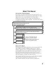
Page 9: ...og Signal Generator Operation Manual Main frame MG3710A MG3710E Vector Signal Generator Operation Manual Standard Waveform Pattern Waveform Pattern Operation Manuals for each communication system Scope of This Manual This manual mainly describes installation and operation methods of the MG3700A MG3710A MG3710E MG3740A IQproducerTM which is Windows application software for the MG3700A MG3710A MG371...

Page 10: ... Pattern Operation Manuals for Each Communication System In IQproducerTM operation manuals and Waveform Pattern operation manuals for each communication system it is assumed that you use MG3710A unless otherwise noted If you use MG3710E read MG3710A as MG3710E ...

Page 11: ...ine of Product 1 2 1 2 Outline of Functions 1 3 Chapter 2 Installation 2 1 2 1 Operating Environment 2 2 2 2 Installation and Uninstallation Procedure 2 3 Chapter 3 Basic Operations 3 1 3 1 Operations for Menu 3 2 3 2 Operations for Dialog Box 3 4 3 3 Using Touch Panel 3 7 ...

Page 12: ...mbining Waveform Patterns by Combination File Edit Function 4 105 4 9 Generating AWGN Waveform Pattern 4 116 4 10 W CDMA Downlink Waveform Pattern Generation Function 4 122 4 11 W CDMA Uplink Waveform Pattern Generation Function 4 153 4 12 Help Screen 4 179 4 13 Time Domain Graph Display 4 180 4 14 Clipping Function 4 198 Chapter 5 Detail Description 5 1 5 1 Installing License File 5 2 5 2 Transfe...

Page 13: ...cation corresponding to communications system 1 3 1 2 2 CCDF graph display function 1 3 1 2 3 FFT graph display function 1 3 1 2 4 File conversion function 1 3 1 2 5 Transfer Setting function 1 4 1 2 6 Combination file edit function 1 4 1 2 7 AWGN waveform pattern generation function 1 4 1 2 8 Time domain graph display function 1 4 1 2 9 Clipping function 1 4 ...

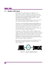
Page 14: ...m file generated by the modulated waveform pattern generator IQproducerTM hereafter referred to as signal generation application corresponding to each communications system with the MG3700A MG3710A MG3710E MG3740A The IQproducerTM for MG3700A MG3710A MG3710E MG3740A also enables to display the Complimentary Cumulative Distribution Function CCDF results and Fast Fourier Transform FFT results of a g...

Page 15: ...odulation waveform pattern generated by each signal generation application and display it in the FFT graph with up to four traces The FFT graph displayed on the screen can be printed out and saved into a CSV format file 1 2 4 File conversion function The IQproducerTM for MG3700A MG3710A MG3710E MG3740A can convert an ASCII format waveform pattern generated by simulation software or other external ...

Page 16: ...s of multiple waveform patterns to be allocated in the arbitrary waveform memory on the MG3700A MG3710A MG3710E MG3740A This function enables definition of additional combinations of two waveform patterns as well as time series switching among multiple waveform patterns while keeping signal synchronization 1 2 7 AWGN waveform pattern generation function This function enables generation of AWGN wav...

Page 17: ...o install uninstall the IQproducerTM for MG3700A MG3710A MG3710E MG3740A in a PC 2 1 Operating Environment 2 2 2 2 Installation and Uninstallation Procedure 2 3 2 2 1 Installation procedure 2 5 2 2 2 Upgrade procedure 2 7 2 2 3 Uninstallation procedure 2 8 ...

Page 18: ...oducerTM Version 16 01 or earlier Windows XP Windows Vista Windows7 IQproducerTM Version 17 00 or later Windows7 Windows10 CPU PentiumIII 1 GHz equivalent or faster Memory 512 MB or more Hard disk free space 5 GB or more free space on the drive where the IQproducerTM is to be installed Peripheral device Display Displays with a resolution of 1024 768 pixels are best viewed using a small font settin...

Page 19: ...t was disabled on your Windows old software cannot be uninstalled In this case instead of uninstalling the old software execute the setup file of the new software and specify the installation folder of the old software for the Destination Folder thereby installing the new software while overwriting the old one Note Versions 12 00 and later of this software are installed in a different default dest...

Page 20: ... to as old software has been installed the automatic uninstallation of the old software starts When the old software has been successfully uninstalled the installation of the new software starts Note To downgrade from IQproducerTM version 14 02 or later hereafter referred to as new software to IQproducerTM version 14 01 or earlier hereafter referred to as old software uninstall the new software be...

Page 21: ...double click the SETUP EXE file in the IQproducer directory of the setup disk 2 If Microsoft Visual C 2010 Redistributable Package x86 is not installed to your PC start the installation of the package Figure 2 2 1 1 Installation of the Microsoft Visual C 2010 Redistributable Package 3 When Microsoft Visual C 2010 Redistributable Package x86 version 10 0 30319 or later has been already installed th...

Page 22: ...ftware will be installed is displayed in the Destination Folder field When changing the installation folder click the Browse button to open the directory change dialog box and specify the desired folder In this event be sure to confirm that there is enough free space in the drive where the target folder belongs to For free space refer to Section 2 1 Operating Environment The IQproducerTM for MG370...

Page 23: ...cribed in step 2 of 2 2 1 Installation procedure Follow step 2 of 2 2 1 Installation procedure 3 Follow step 3 of 2 2 1 Installation procedure 4 When you see the following message after the IQproducerTM setup program starts click the Yes button The setup will perform an upgrade of IQproducer Do you want to continue 5 When you see the following message click the Next button to start upgrade Resumin...

Page 24: ...be displayed during uninstallation asking whether to remove a shared file Select NO unless it is not certain whether the indicated file is shared by any other programs Some programs may not function correctly if a necessary shared file is removed inadvertently 7 When Uninstallation Complete is displayed click the Finish button Note If a shared file is removed there is a possibility that other appl...

Page 25: ...3700A MG3710A MG3710E MG3740A on Windows 3 1 Operations for Menu 3 2 3 1 1 Operations using mouse 3 2 3 1 2 Operations using keyboard 3 2 3 1 3 Operations using up and down cursor keys 3 3 3 2 Operations for Dialog Box 3 4 3 2 1 File Open Save as 3 4 3 2 2 Entering numeric value and character string 3 6 3 3 Using Touch Panel 3 7 ...

Page 26: ... button indicates a left button unless otherwise specified Drag To press a mouse button and then move the mouse while holding down the button The button indicates a left button unless otherwise specified Figure 3 1 1 1 Screen explanation 1 Click a menu on the menu bar File Edit etc to display the pull down menu 2 Select an item to be executed from the displayed pull down menu and click it 3 1 2 Op...

Page 27: ...ected by pressing the underscored character in that item on the menu bar and pull down menus Such a key is referred to as accelerator key For example the accelerator key for the Recall Parameter file item is R and for Exit E When selecting an item on the menu bar however it is necessary to activate the menu bar an item is highlighted when the menu bar is activated by pressing Alt ...

Page 28: ...ess Tab several times to highlight the Look in or Save in box then press the up or down cursor key to open the pull down list of drives and folders Use the cursor keys to select the target drive or folder from the list and then press Enter 2 Select a file type from the Files of type text box For the mouse operation click the Files of type text box to open the list of file types Select the target f...

Page 29: ... several times to move the cursor to the folder file display field highlighted when selected and use the cursor keys to select the file or folder to be opened Then press Enter to open the selected file folder 5 When saving a file with a specified name highlight the File name text box by clicking it mouse operation or pressing Tab several times keyboard operation Next type the desired file name in ...

Page 30: ...ze the entered value 2 When entering a character string click the desired character string entry text box using the mouse or move the cursor to the desired character string entry text box by pressing Tab several times Enter a character string from the keyboard Then click the OK button using the mouse or press Enter to input finalize the entered character string 3 The numeric value character string...

Page 31: ...screen provides the same operation as a click of a mouse Button Same operation as a click of a mouse Numeric input If numeric input box is touched while running on MG3710A MG3710E MG3740A a numeric keypad will display Note that there is a numeric input text box without numeric keypad Figure 3 3 1 Numeric Input Using Touch Panel ...

Page 32: ...If text input box is touched while running on MG3710A MG3710E MG3740A a screen keyboard will display Note that there is a text input box without screen keyboard Once and is touched it is locked and grayed out as Touching again will release the lock ...

Page 33: ... 4 3 1 Activation 4 14 4 3 2 CCDF graph display screen 4 14 4 3 3 CCDF graph display 4 16 4 3 4 Deleting CCDF graph 4 19 4 3 5 Displaying Gaussian trace 4 20 4 3 6 Interaction with signal generation application Quick Add Mode 4 20 4 3 7 Mouse interaction selection in the CCDF graph display area Mouse Interaction 4 22 4 3 8 Moving graph cursor 4 23 4 3 9 Changing graph scale 4 25 4 3 10 Printing sa...

Page 34: ...display area 4 95 4 6 10 Status display 4 95 4 6 11 Disconnection screen 4 96 4 6 12 Rename screen for changing file name 4 97 4 6 13 Create new folder screen for inputting folder name 4 98 4 7 File Transfer and Loading to Memory Using Transfer Setting Wizard 4 99 4 7 1 Activation 4 99 4 7 2 Transfer Setting Wizard Step 1 2 Connection screen 4 99 4 7 3 Transfer Setting Wizard Step 2 2 File selecti...

Page 35: ... 11 4 Channel Gain Setup screen 4 169 4 11 5 Saving reading parameters 4 170 4 11 6 Generating waveform pattern file 4 171 4 11 7 Calculation Load 4 176 4 11 8 Calculation Play 4 177 4 11 9 Auxiliary signal output 4 178 4 12 Help Screen 4 179 4 13 Time Domain Graph Display 4 180 4 13 1 Activation 4 180 4 13 2 Time domain graph display screen 4 181 4 13 3 Displaying time domain graph by reading fil...

Page 36: ...ion 4 198 4 14 2 Clipping setting screen 4 198 4 14 3 Setting method 4 202 4 14 4 Generating waveform pattern 4 203 4 14 5 Calculation Load 4 206 4 14 6 Calculation Play 4 207 4 14 7 Clipping processed waveform pattern simulation examples 4 208 4 14 8 Details of clipping processing 4 210 ...

Page 37: ...ick the Start button on the Windows task bar and select Programs Then select Anritsu Corporation from the displayed program group and click IQproducer Figure 4 1 1 1 Program Selection Screen 2 When the IQproducerTM is started the Select instrument window is displayed From the Select instrument options select the main unit model that will use the waveform patterns created by IQproducerTM ...

Page 38: ...again select the Don t show this window next time check box and IQproducerTM will start for the selected model from the next startup without displaying the Select instrument window 3 The common platform screen is displayed after starting up the IQproducer The common platform screen is a screen used to select each function of the IQproducer Figure 4 1 1 2 Common Platform Screen ...

Page 39: ...S2840A Start the IQproducerTM by following the procedures below Procedure 1 Click Start and point to All Programs Point to Anritsu Corporation from the program group and click IQproducer Figure 4 1 2 1 Program Selection Screen 2 The further procedure is as same as that of 4 1 1 Starting Software When installed on PC ...

Page 40: ... below Procedure 1 Press on the MG3710A MG3710E MG3740A front panel Note IQproducer starts only when the digital modulation option 020 120 is installed to MG3740A 2 The common platform screen is displayed after starting up the IQproducer The common platform screen is a screen used to select each function of the IQproducer Figure 4 1 3 1 Common Platform Screen ...

Page 41: ...producerTM 4 9 4 1 4 Exiting Software To exit IQproducer that are running select Exit on the Common Platform Screen In this case a dialog is displayed to confirm stopping of each running tool Figure 4 1 4 1 Exiting IQproducer ...

Page 42: ...ations are displayed on the tabbed page For detailed information about the signal generation applications refer to the operation manual for each application The System Cellular tab does not appear when MG3740A is clicked in the Select Instrument window or the IQproducer is started on MG3740A 2 System Non Cellular tab Non cellular system applications are displayed on the tabbed page For detailed in...

Page 43: ...tions are displayed Modulated waveform patterns corresponding to Multi Carrier system specifications are created in this application This is not displayed when MG3740A is clicked in the Select Instrument window or the IQproducer is started on MG3740A 3 Fading Fading applications are displayed The fading operation is applied onto input waveforms to output the results 4 Convert The Convert screen is...

Page 44: ...r parameters on the AWGN generation screen This is not displayed when MG3740A is clicked in the Select Instrument window or the IQproducer is started on MG3740A 6 Clipping The Clipping setting screen is displayed Clipping processing can be performed in the Clipping setting screen for a waveform pattern generated by each signal generation application 4 Simulation Utility tab Application menus of si...

Page 45: ...when installing key files or transferring waveform patterns 5 Transfer Setting Wizard The Transfer Setting Wizard screen is displayed Connection between a PC and the mainframe transfer of waveform patterns to the mainframe and loading of waveform patterns to an arbitrary waveform memory of the mainframe can be performed on this screen 5 Change Instrument button Provided to display the Select instr...

Page 46: ...al is equal to or less than the value on the X axis is displayed Distribution of peak powers of various modulation signals can be displayed in a screen This screen is useful for example for estimating the output waveform distortion characteristics when a generated signal is input from the MG3700A MG3710A MG3710E MG3740A to a power amplifier or other devices 4 3 1 Activation Select CCDF from the Si...

Page 47: ...ampling points can be set by changing the value in this text box 7 Sampling information display The sampling range for the selected trace is displayed A different sampling range can be set by changing the value in this text box 8 Cursor Position The current graph cursor position is displayed The graph cursor position in the CCDF graph display area can be specified by entering a value in either PAR...

Page 48: ...the option buttons in the Legend dialog box to select the trace color of the wave form pattern in the CCDF graphical area Figure 4 3 3 1 Legend Dialog Box 2 Click the Add button to display the Add Trace dialog box The Add button is disabled when any waveform pattern is already specified on the selected option button In such case delete the waveform pattern by clicking the Delete button or select o...

Page 49: ...tern for which a CCDF graph is displayed Enter the Sampling Points and Sampling Range for the waveform to be shown on the CCDF graphic area If the target area includes the RF Gate OFF area RF output is set to off at this time the RF Gate OFF interval can be excluded from the CCDF graph display target by selecting the Exclude RF Output Off Sample check box Figure 4 3 3 4 Add Trace Dialog Box ...

Page 50: ... 3 5 Graph Calculation Progress Screen If the Cancel button is clicked during the graph calculation the calculation is interrupted and waveform pattern reading is stopped After the completion of the reading and calculations of the waveforms the Graph calculation progress screen will be closed to display the CCDF graphic window The trace in the selected color in the Legend dialog box will be indica...

Page 51: ... the Legend dialog box to select the trace to be deleted Exclusively selectable Figure 4 3 4 1 Legend Dialog Box 2 Click the Delete button Figure 4 3 4 2 Delete Button Otherwise select Delete Trace from the File menu Figure 4 3 4 3 Delete Trace Button on the File Menu The trace selected in Legend is deleted After deleting a trace another waveform pattern can be selected for that item ...

Page 52: ...k Add Mode The method for adding a trace to the CCDF graph in conjunction with a signal generation application can be set and changed This function is enabled only when the CCDF graph display function is activated Click the Quick Add Mode button to display the Quick Add Mode dialog box Figure 4 3 6 1 Quick Add Mode Dialog Box When Add is selected A trace is added to the CCDF graph when CCDF is sel...

Page 53: ...ayed when CCDF is selected from the Simulation menu or the CCDF tool button is clicked after data generation by the signal generation application When Off is selected The CCDF graph display will not be updated even when CCDF is selected from the Simulation menu or the CCDF tool button is clicked after data generation by the signal generation application ...

Page 54: ...on Graph cursor move or graph zoom in is selected for a mouse dragging operation in the CCDF graph display area Click the Mouse Interaction button to display the Mouse Interaction dialog box Cursor The mouse is used to move the cursor Zoom The mouse is used to set the zooming area Figure 4 3 7 1 Mouse Interaction Dialog Box ...

Page 55: ...sor using mouse When the Cursor radio button is selected in Mouse Interaction the black line graph cursor is moved by dragging the mouse on the graph cursor in the CCDF graph display area Figure 4 3 8 1 CCDF Graph Display Area The contents displayed in Cursor Position in the CCDF graph display screen are updated as the graph cursor is moved ...

Page 56: ...cedure 1 When setting the graph cursor position by a Peak Power Average Power value click the PAR text box and enter a value 2 When setting the graph cursor position by a cumulative possibility click the Probability text box and enter a value When the focus is moved to another control after changing the value in the PAR or Probability text box as shown in Step 1 or 2 above the black line graph cur...

Page 57: ...ed by changing the value s in the Scale field on the CCDF graph display screen Figure 4 3 9 1 Scale Dialog Box Procedure 1 When changing the display range for the X axis click the PAR text box and enter a value 2 When changing the display range for the Y axis click the Probability text box and enter a value 3 When the Full Scale button is clicked the scales for both axes are adjusted so that the e...

Page 58: ... is updated Similarly when the focus is moved after changing the value in the Probability text box as shown in Step 2 above the scale for the Y axis in the CCDF graph display area is updated Figure 4 3 9 2 CCDF Graph Display Area Specifying display area by mouse operation When Zoom is selected for Mouse Interaction pointing and dragging an area in the graph enlarges the selected area within the do...

Page 59: ...nu Outputting graph data to file Select Export Data from the File menu to display the file save screen Set the saving destination etc in this screen and click the Save button Lists of Peak per Average dB and Probability are saved to a file in the CSV format a text file format in which values are delimited by a comma Figure 4 3 10 2 Export Data Button on the File Menu Copying graph image on screen ...

Page 60: ...tility tab on the common platform screen The FFT graph display screen is displayed separately 4 4 2 FFT graph display screen Figure 4 4 2 1 FFT Graph Display Screen Description of items 1 Menu bar Trace addition graph print out screen copy graph data saving into a CSV format file and FFT graph display close can be executed 2 Legend File name display for an added trace selection of a displayed trac...

Page 61: ... display area can be specified by entering a value in the Frequency text box 7 Quick Add Mode interaction with signal generation application Settings for addition of a waveform pattern generated by a signal generation application to the FFT graph display in conjunction with the signal generation application can be configured 8 Scale setting The scale of the X and Y axes in the FFT graph display ar...

Page 62: ...dure 1 Click one of the option buttons in the Legend dialog box to select the trace color of the wave form pattern in the FFT graphical area Figure 4 4 3 1 Legend Dialog Box 2 Click the FFT Points button to display the FFT Points dialog box Then Select the number of points for FFT operation Be sure to select a value smaller than the number of sample points of the selected waveform pattern Figure 4...

Page 63: ... button In such a case delete the waveform pattern by clicking the Delete button or select one of other option buttons Figure 4 4 3 3 Add Button Otherwise select Add Trace from the File menu Figure 4 4 3 4 Add Trace Button on the File Menu 4 Click the button in the Add Trace screen and select a waveform pattern for which a FFT graph is displayed Figure 4 4 3 5 Add Trace Dialog Box ...

Page 64: ...rm pattern When the graph calculation has completed the FFT graph display screen is displayed again with a trace in the color selected in Legend If a waveform pattern having a different sampling rate with that of the currently displayed waveform pattern is added the current waveform pattern display disappears ...

Page 65: ... the Legend dialog box to select the trace to be deleted Figure 4 4 4 1 Legend Dialog Box 2 Click the Delete button Figure 4 4 4 2 Delete Button Otherwise select Delete Trace from the File menu Figure 4 4 4 3 Delete Trace Button on the File Menu The trace selected in Legend is deleted After deleting a trace another waveform pattern can be selected for that item ...

Page 66: ...ved to another control after selecting the FFT Points value the plot interval of the X axis in the graph display area is changed 2 Click the Sampling Range text box and enter the Sampling Range value When the focus is moved to another control after changing the Sampling Range value the data range of the waveform pattern for FFT analysis is changed When the FFT Points value is changed the new FFT P...

Page 67: ... selected from the Simulation menu or the FFT tool button is clicked after data generation by the signal generation application Note that the FFT graph display will not be updated when the four traces are all used When Clear is selected A trace is deleted from the FFT graph and the FFT analysis result of the generated data is displayed when FFT is selected from the Simulation menu or the FFT tool ...

Page 68: ...ion Graph cursor move or graph zoom in is selected for a mouse dragging operation in the FFT graph display area Click the Mouse Interaction button to display the Mouse Interaction dialog box Cursor The mouse is used to move the cursor Zoom The mouse is used to set the zooming area Figure 4 4 7 1 Mouse Interaction Dialog Box ...

Page 69: ...lack line graph cursor is moved by dragging the mouse on the graph cursor in the FFT graph display area Figure 4 4 8 1 FFT Graph Display Area The contents displayed in Cursor in the FFT graph display screen are updated as the graph cursor is moved Moving graph cursor changing Cursor value The black line graph cursor is moved by changing the value of Cursor in the FFT graph display screen Figure 4 ...

Page 70: ...the FFT graph display screen Figure 4 4 9 1 Scale Dialog Box Procedure 1 Click the Frequency text box and enter the Frequency value from the keyboard 2 Click the Amplitude text box and enter the Amplitude value 3 When the Full Scale button is clicked the scales for both axes are adjusted so that the entire FFT graph is displayed When the focus is moved to another control after changing the value i...

Page 71: ...39 Figure 4 4 9 2 FFT Graph Display Area Specifying display area by mouse operation When Zoom is selected for Mouse Interaction pointing and dragging an area in the graph enlarges the selected area within the dotted rectangle ...

Page 72: ...File Menu Outputting graph data to file Select Export Data from the File menu to display the file save screen Set the saving destination etc in this screen and click the Save button Lists of Peak per Average dB and Probability are saved to a file in the CSV format a text file format in which values are delimited by a comma Figure 4 4 10 2 Export Data Button on the File Menu Copying graph image on ...

Page 73: ...option 512Msamples for the MG3700A When With Option21 Memory 512M samples is selected the maximum size of the waveform pattern is expanded A waveform pattern exceeding 256 Msamples cannot be used when the ARB memory expansion option 512Msamples is not installed Select either With Option21 or Without Option21 according to whether the ARB memory expansion option 512Msamples is installed in the MG370...

Page 74: ...RB Memory Expansion option and Baseband Signal Combination Function option is selected Selecting the ARB Memory Expansion option and the Baseband Signal Combination Function option generates a bigger waveform pattern while selecting the Baseband Signal Combination Function option generates a waveform pattern If an uninstalled option is selected sometimes the created waveform pattern may not be usa...

Page 75: ...14 bit 1 to 8191 Marker 1 to 3 RF Gate 15 bit 1 to 16383 Marker 1 RF Gate 16 bit 1 to 32767 None The specifiable bit widths differ for each conversion file format as follows Table 4 5 4 Available Bit Width per Each Input File Format Input File Format Selectable Bit Width ASCII1 14 15 16 bit ASCII2 15 16 bit ASCII3 14 15 bit MS269x MS2830 MS2840 Digitizer 14 15 16 bit MG3710 MG3740 MS269x MS2830 MS...

Page 76: ...unction 4 44 4 5 1 Activation Click the Convert button on the General Purpose tabbed box in the Common Platform Screen The Convert screen is displayed separately 4 5 2 Convert screen Figure 4 5 2 1 Convert Dialog Box for the MG3700A ...

Page 77: ...t field The number of files to be selected varies depending on the file format setting 2 File data setting Set the data to be written in the waveform information file wvi format of the waveform pattern to be generated 3 File format The format of the file to be converted ASCII1 ASCII2 ASCII3 MS269x MS2830 MS2840 Digitizer MG3710 MG3740 MS269x MS2830 MS2840 to MG3700 MG3700 MS269x MS2830 MS2840 to M...

Page 78: ...d only when the file format is set to ASCII1 ASCII2 ASCII3 or MS269x MS2830A MS2840A Digitizer When the RF Gate checkbox is selected RF Gate processing is performed during waveform pattern conversion for samples in which the I and Q values jQ I of the input ASCII file or digitized file data are continuously at or below the threshold level The threshold level can be set by entering the ratio to the...

Page 79: ...e data file ASCII3 Three files of I phase data file Q phase data file and marker data file MS269x MS2830 MS2840 Digitizer xml file which is a digitized file created by the MS2690A MS2691A MS2692A MS2830A or MS2840A Signal Analyzer using the digitize function MG3710 MG3740 MS269x MS2830 MS2840 to MG3700 Of the wvi and wvd files which are waveform patterns for the MG3710A MG3710E MG3740A MS269xA or ...

Page 80: ...red 3 In the MG3710 MG3740 mode the dialog box below for selecting the bit width appears after selecting the input file Specify 14 15 or 16 bits However the bit widths that can be specified depend on the selected file format as shown in Table 4 5 4 Figure 4 5 3 2 Output IQ Data Width Dialog Box 4 When the input files are selected they are read and a dialog box appears displaying the maximum value ...

Page 81: ...t File Information Dialog Box Click the OK button to finalize the input file selection Click the Cancel button to cancel the input file selection If the file format is changed in the File format box after selecting the input files the current settings are cleared ...

Page 82: ... rate can be set from 20 kHz to 160 MHz Note When the IQproducerTM operates in the MG3740 mode the setting range for the sampling rate is 20 kHz to 8 MHz 2 Click the button on the right of the Sampling Rate box to open a pull down menu and select the unit of the sampling rate The unit can be set from Hz kHz and MHz Figure 4 5 4 1 Sampling Rate Dialog Box Setting Low pass filter Effective only for ...

Page 83: ...urce file to leave a checkmark Figure 4 5 4 3 Normalizing Check Box The RMS value of the standard waveform pattern used by the MG3700A MG3710A MG3710E MG3740A Indicates the following RMSI and RMSQ n n n IQ Q I N RMS 2 2 1 n n I I N RMS 2 1 n n Q Q N RMS 2 1 Where Σ is the sum of target waveform patterns except the samples of which RF output is set to OFF by RF Gate RMSI indicates the RMS value for...

Page 84: ...n Normalization is selected a crest factor Peak Power RMS Power of 17 dB can be obtained if the signal output is set within the level assurance range Setting RMS and Peak values When reading a waveform pattern the data is read from the conversion source file and the RMS and Peak values are calculated and displayed Click the RMS Value box and enter an RMS value of the waveform after conversion to b...

Page 85: ...eed upper limit value for the RMS value range and the upper limit setting level for RF output signal stable distortion characteristics are shown in the Tables 4 5 4 3 and 4 5 4 4 below Table 4 5 4 3 The Maximum Guaranteed Output Level Frequency For standard composition When a mechanical attenuator option is installed 50 MHz f 3 GHz 2 χ dBm 7 χ dBm 3 GHz f 6 GHz if Upper limit frequency 6 GHz optio...

Page 86: ...e Normalizing checkbox is selected and the RMS and Peak values are automatically specified but the values can be manually specified to adjust the characteristics for signals that have a crest factor larger than 17 dB Note that the RF output level reliability for the MS2830A is specified assuming the following RMS values Table 4 5 4 5 RMS Setting Range of Guaranteed Output Level Bit Width RMS value...

Page 87: ...sion option and Baseband Signal Combination Function option is selected Selecting the ARB Memory Expansion option and the Baseband Signal Combination Function option generates a bigger waveform pattern while selecting the Baseband Signal Combination Function option generates a waveform pattern If an uninstalled option is selected sometimes the created waveform pattern may not be usable Set this pa...

Page 88: ... 7 Memory Option Menu and Maximum Data Points MG3740A Memory Option Menu Maximum data points Memory 64M samples 64M samples Memory 64M samples 2 With Option48 78 128M samples Memory 256M samples 256M samples Memory 256M samples 2 With Option 48 78 512M samples No manual setting is available when this software is hosted by the MG3740A since it is set automatically Setting package name Enter the nam...

Page 89: ... numeric value For example to specify a sampling rate of 4 MHz for signals that have a 1 MHz symbol rate enter 4 Figure 4 5 4 11 Over Sampling Dialog Box Setting Data Points available for ASCII1 ASCII2 and ASCII3 The number of sample points of the read waveform pattern is displayed in the Data Points box Usually this setting is not required to be changed In case of change enter the value into the ...

Page 90: ... to leave a checkmark Then the input area and the Reference button become enabled Click the input area and enter the directory of the target detail file directly or click the Reference button to display the file dialog box and locate the target detail file The contents of the detail file selected here can be displayed on the screen when the MG3700A selects the corresponding waveform pattern Figure...

Page 91: ...Length Refer to Section 5 4 Generating Waveform Pattern for details Figure 4 5 4 16 Burst Setting Dialog Box Configuring RF Gate settings for digitized and ASCII file and file conversion To configure the RF Gate settings click the RF Gate check box to leave a checkmark The RF On Off Threshold and Minimum RF Gate Length boxes will then become enabled Click an input area and enter a numeric value to...

Page 92: ...file after conversion conversion destination file before executing conversion Procedure 1 Click the Convert button to display the Export File screen shown in Figure 4 5 5 2 below Figure 4 5 5 1 Convert Execution Button Figure 4 5 5 2 Export File Dialog Box In MG3700 mode Figure 4 5 5 3 Export File Dialog Box In MG3710 MG3740 mode ...

Page 93: ...his software Output destination MG3710A MG3710E MG3740A C Anritsu MG3710A User Data Waveform Package name An output destination file other than the above can be assigned Hosted by PC in MG3710 MG3740 mode Corresponding to the Export Path setting in the Export File dialog box Other than the above Corresponding to the Export Path setting in the Export File dialog box 3 Click the Export File Name box...

Page 94: ...able when executing in MG3710A MG3710E MG3740A 4 Click the OK button to start conversion After this if a clipping occurs during the conversion the warning message The waveform pattern to be generated will be above 8191 and be clipped is displayed If the OK button on the warning message dialog box is clicked at this time to continue the conversion as is a waveform pattern for which clipping has bee...

Page 95: ... MS269xA or MS2830A MG3700 MS269x MS2830 MS2840 to MG3740 The waveform pattern formatted for MG3700A MG3710A MG3710E MG3740A MS2830A or MS2840A MG3700 MG3710 MG3740 MS2830 MS2840 to MS269x The waveform pattern formatted for MG3700A MG3710A MG3710E MG3740A or MS269x MG3700 MG3710 MG3740 MS269x to MS2830 MS2840 This section describes the ASCII format files The following data are included in each of ...

Page 96: ...G3710A MG3710E MG3740A Marker1 AUX The output signal is specified depending on the MG3710A MG3710E MG3740A settings as shown Table 4 5 6 1 MG3710A MG3710E MG3740A Marker Signal Generating SG Waveform memory Signal name SG1 Memory A SG1 Marker1 A SG1 Marker2 A SG1 Marker3 A SG1 Memory B SG1 Marker1 B SG1 Marker2 B SG1 Marker3 B SG2 Memory A SG2 Marker1 A SG2 Marker2 A SG2 Marker3 A SG2 Memory B SG2...

Page 97: ... pulse modulator of the MG3700A MG3710A MG3710E MG3740A at almost the same time when the IQ phase data corresponding to the RF Gate data is input to the pulse modulator The pulse modulation timing for the RF output can be adjusted therefore by applying RF Gate 0 at the same position with the IQ phase data where the RF signal is required to be Off When the data for both the I and Q phases are set t...

Page 98: ...Vector modulator Pulse modulator 3 Markers 1 2 3 RF Gate Delay 3 Waveform data Sample 2 Sample 1 RF Gate Sample 3 Sample 4 1 0 1 0 RF output ON OFF ON ON Waveform data 14 bits 2 ch Figure 4 5 6 4 Waveform Pattern Generator Block Diagram and Output Signal Timing Chart of Mainframe ...

Page 99: ...xponential notation such as 2 0E 3 IQ Data Comment Line 0 214178 0 984242 0 187286 1 245890 0 073896 1 368888 0 091758 1 316199 0 073896 1 368888 1 Marker1 1 is output 0 091758 1 316199 0 1 Marker2 1 is output 0 248275 1 089333 0 0 1 Marker3 1 is output 0 331432 0 729580 0 0 0 0 RF output becomes Off 0 331432 0 729580 0 0 1 Marker1 0 is output and RF output becomes On ASCII 2 Waveform patterns bef...

Page 100: ... line is added to the start of one of these files it is necessary to adjust the number of lines among the files by adding a comment line or cr lf to other files An error occurs if the number of lines differs between the I phase data and Q phase data If Markers 1 through 3 and RF Gate data exists in a line where I phase and Q phase data do not exist it is regarded that line has no data If the data ...

Page 101: ...two comment lines are added in the I phase data cr lf 0 984242 1 245890 1 368888 1 316199 1 089333 0 729580 File 3 Marker data cr lf cr lf cr lf Markers 1 through 3 0 and RF Gate 1 for the third and fourth lines cr lf 1 Corresponds to the fifth line data in the I phase and Q phase data 0 1 0 0 1 1 0 0 1 ...

Page 102: ...n Display Button For details about using the Time Domain screen to specify the RMS value calculation range see Section 4 13 13 Displaying the Time Domain screen from the Convert screen When the RMS value calculation range is set the RMS value for the waveform pattern is recalculated and the value in the Peak Value text box is updated Using the above function makes it possible to prevent the ratio ...

Page 103: ...rget Instrument dialog box and also enter the host name or IP address for the Ethernet connection Then click the Connect button to establish the connection Note If the MG3700A firmware version is 1 xx the warning message The MG3700A firmware version is 1 xx Your version of IQproducer cannot connect with the version 1 xx of MG3700A normally Please check Anritsu Download Support Site to upgrade MG37...

Page 104: ...Dialog Box When changing the network setting of the MG3700A MG3710A MG3710E MG3740A to DHCP Off and connecting the MG3700A MG3710A MG3710E MG3740A and PC using a LAN cross cable restart the MG3700A MG3710A MG3710E MG3740A after network setting change before connecting a LAN cross cable ...

Page 105: ...red the waveform transfer is processed continuously and completed without interruption When the Advanced button is clicked the Advanced screen is displayed where the following items can be set Figure 4 6 1 2 Advanced Dialog Box 1 Host name or IP address Enter the host name or IP address of the mainframe to be connected 2 FTP user ID Enter the user name used in FTP login 3 FTP password Enter the pa...

Page 106: ...740A User ID MG3700 ANRITSU password password anritsu FTP port 21 21 Remote port 49153 49158 Remote wait 10 msec 10 msec 8 OK Finalizes the settings and closes the screen when clicked 9 Cancel Cancels the settings and closes the screen when clicked Note Connection with the MG3700A MG3710A MG3710E MG3740A is possible when the parameters are set to the default values Do not change the parameters in ...

Page 107: ...r selection box PC side file display area SG side file display area logs and status bar Right clicking in the PC SG side file display area opens a pop up menu Description of items 1 Menu bar Connection disconnection to the network termination of Transfer Setting deletion of files folders in the PC side creation of new folders updating of file information file transfer and loading to memory can be ...

Page 108: ...lay area Displays the information of the folders and files stored in the internal hard disk of the MG3700A MG3710A MG3710E MG3740A 6 Transfer file type selection box The type of the file to be transferred via FTP can be selected 7 Status bar Displays the free space and total space of the internal hard disk and waveform memories A and B of the current mainframe Nothing is displayed when several mai...

Page 109: ...ect Connects with the mainframe The Connection dialog box is displayed when this item is selected The contents of the connected MG3700A MG3710A MG3710E MG3740A are displayed in the SG side file display area 2 Disconnect Disconnects the connection with the MG3700A MG3710A MG3710E MG3740A currently connected The Disconnection dialog box is displayed when this item is selected 3 Exit Closes the Trans...

Page 110: ...firmation Cancel Cancels the deletion of the selected combination file and the corresponding files When a combination file is selected for deletion the Delete dialog box shown in Figure 4 6 3 4 below is displayed Figure 4 6 3 4 Delete Dialog Box Apply to all check box The deleting operation will apply to all the selected combination files when this check box is selected Yes Also deletes the files ...

Page 111: ...tion File Edit screen Refer to Section 4 8 Combining Waveform Patterns by Combination File Edit Function for details on this function 3 View Figure 4 6 3 5 View Selection Screen 1 Refresh Updates the contents currently displayed in the PC side file display area and SG side file display area to the latest information 2 Toolbar Toggles tool bar display non display The tool bar is displayed in the Tr...

Page 112: ...n the combination file are transferred at the same time 2 SG to PC Transfers files selected in the SG side file display area to the folder selected in the PC side file display area 3 PC to All SG Transfers files such as waveform pattern selected in the PC side file display area to the internal hard disks of all the connected mainframe units in the SG side file display area The transfer destination...

Page 113: ...In the SG side file display area loads the selected waveform pattern into the waveform memory A of the specified SG 4 Load Pattern to Memory B In the SG side file display area loads the selected waveform pattern into the wave memory A of the specified SG 5 Remove Pattern from Memory A In the SG side file display area removes the selected waveform pattern from the wave memory A of the specified SG ...

Page 114: ...ed when there is no need to execute defrag or when several MG3700A units are selected Note This function is available only when MG3700A is connected 9 Edit Mode Defined Mode Changes the waveform pattern output mode of the selected SG In the Defined Mode one of the patterns or combination files loaded in the waveform memory A or B is selected as an output waveform pattern In the Edit Mode one outpu...

Page 115: ...n loading a waveform pattern the overwrite confirmation dialog box is displayed The meaning of each selection item in this dialog box is as follows Yes The waveform pattern is loaded in the target memory overwriting the existing waveform pattern in the memory No The waveform pattern is not loaded and the subsequent memory load processing is executed as required Cancel Or The waveform pattern is no...

Page 116: ...lder Selection Dialog Box 2 Folder move button When this button is clicked the contents of the previous directory are displayed When this button is clicked in the root directory the drives connected to the PC are displayed in a list 3 Current folder path display input box The path of the currently selected folder is displayed Also the display path can be changed by entering the folder path from th...

Page 117: ...e drop down list Can be selected in the drop down combo box The following file types are listed in the drop down menu Waveform Pattern Combination File Waveform Package License File All File When Waveform Pattern File or Waveform Package License File is selected only the corresponding files that can be transferred are displayed in the PC SG side file display areas When All File is selected all the...

Page 118: ... Display Area The following contents are displayed in the SG side file display area 1 MG3700A MG3710A MG3710E MG3740A units currently connected 2 The host names or IP addresses of the MG3700A MG3710A MG3710E MG3740A units currently connected are displayed 3 The folders and files stored in the hard disk of each mainframe can be displayed by double clicking the mainframe icon Only the files that hav...

Page 119: ...tatus to an arbitrary waveform memory A indicates that the waveform pattern combination file is loaded to the arbitrary waveform memory A and B indicates loading to the arbitrary waveform memory B A B indicates that the waveform pattern combination file is loaded to both the arbitrary waveform memories A and B Mem loaded indicates that the waveform pattern combination file is loaded to the wavefor...

Page 120: ...de as follows Defined Mode The waveform pattern is output from the memory B Edit Mode The waveform pattern is output from both the memories A and B 2 For license file transfer when Waveform Package License File is selected for transfer file type Figure 4 6 6 3 SG Side File Display Area When Waveform Package License File Is Selected Information of displayed files Name Displays the names of licenses...

Page 121: ...e APP_LICENSE Not used APPLICATION Not used BERTLOG BERT log file CHANNEL Channel table file COMPLEMENT Correction value FIRMWARE MG3700A MG3710A MG3710E MG3740A firmware file IPL MG3700A MG3710A MG3710E MG3740A IPL Initial Program Loader file PACKAGE Waveform pattern REALTIME Not used RT_LICENSE Not used SCENARIO Scenario file SCREEN_IMAGE Bitmap image file of screen copy SGLOG MG3700A MG3710A MG...

Page 122: ... Display Area View When MG3710A MG3710E MG3740A All File Is Selected 1 Alarm History Alarm indication log file BERT BitPattern User defined pattern of BERT BERT Log BERT log file ChannelTable Channel table file Copy Files Image file of screen copy Corrections Correction file ListTable List Table file Parameter Setting Saved parameter file Waveform Waveform pattern ...

Page 123: ... side file display area Each file in the SG side file display area can be selected by a click Two or more files can be selected by Ctrl click additional selection and Shift click range selection When downloading files to the MG3700A MG3710A MG3710E MG3740A select a file in the PC side file display area and select an MG3700A MG3710A MG3710E MG3740A unit as the transfer destination in the SG side fi...

Page 124: ... Area Only the files that have the extension of the specified file type are displayed The information according to each transfer file type is displayed in the list column units A folder is displayed with its name and created date and dir is displayed for the Size column The other columns are left blank Right clicking in the SG side file display area opens the pop up menu If incomplete transfer is ...

Page 125: ...ackage Displays the names of the packages described in the information files Version Displays the versions of waveform patterns License The O sign is indicated on the waveform pattern of which license is installed in the mainframe selected in the SG side file display area A waveform pattern for which O is not displayed cannot be used even if it is transferred to the mainframe Size Displays the tot...

Page 126: ...plays the file names Package License Name Displays the license names of the files For waveform pattern authentication files the package names are displayed and the column character strings are changed Version Displays the versions of licenses SG Indicates the name of the mainframe for which the license is authenticated Indicates the IP address or host name used when the mainframe is connected Size...

Page 127: ...ion and Shift click range selection Files that can be downloaded are those actually selected in the PC side file display area only The MG3700A MG3710A MG3710E MG3740A specified as the transfer destination must be selected at this time 4 6 10 Status display Figure 4 6 10 1 Status Display The status bar displays the following information of the MG3700A MG3710A MG3710E MG3740A currently selected Free...

Page 128: ...e MG3700A MG3710A MG3710E MG3740A units currently connected are displayed in the pull down list Select the MG3700A MG3710A MG3710E MG3740A unit to be disconnected from this list 2 Disconnect button Click this button to disconnect the selected MG3700A MG3710A MG3710E MG3740A The Disconnection screen remains displayed even after disconnection 3 Close button Click this button to close the Disconnecti...

Page 129: ...plays the file name to be renamed Enter a new file name 2 OK button Click this button to finalize the entered file name When the entered file name contains an illegal character restricted for file name by Windows an error message is displayed After the error message is closed the new file name input edit is selected prompting to retry 3 Cancel button Click this button to cancel renaming and close ...

Page 130: ...he name of the folder to be created 2 OK button Click this button to finalize the entered folder name When the entered folder name contains an illegal character restricted for folder name by Windows an error message is displayed After the error message is closed the new folder name input edit is selected prompting to retry 3 Cancel button Click this button to cancel folder creation and close the s...

Page 131: ...ng to Memory Using Transfer Setting Wizard 4 7 1 Activation Select Transfer Setting Wizard from the Simulation Utility tab on the common platform screen The wizard dialog box is displayed in the newly opened window 4 7 2 Transfer Setting Wizard Step 1 2 Connection screen Figure 4 7 2 1 Connection Screen ...

Page 132: ...list connection is made in the network at that time 3 Advanced button Click this button to display the Advanced screen 4 Back button This button is used to return to the previous screen This button is disabled in this screen 5 Next button Click this button to start connection When the connection is completed normally the package selection screen is displayed When the connection is failed an error ...

Page 133: ...ss Enter the host name or IP address of the mainframe to be connected 2 FTP user ID Enter the user name used in FTP login 3 FTP password Enter the password used in FTP login 4 FTP port Enter the port number used by FTP 5 Remote port Enter the port number of the remote used for authentication and memory loading 6 Remote wait Set the period between commands 7 Default Restores all the parameter setti...

Page 134: ...1 Remote port 49153 49158 Remote wait 10 msec 10 msec 8 OK Finalizes the settings and closes the screen when clicked 9 Cancel Cancels the settings and closes the screen when clicked Note Connection with the MG3700A MG3710A MG3710E MG3740A is possible when the parameters are set to the default values Do not change the parameters in the Advanced screen unless otherwise required ...

Page 135: ...e Transfer Setting Wizard is activated the folder in which the last waveform pattern was generated by an IQproducer waveform generation application is selected as the default reference folder 2 File list for selection A list of waveform patterns and combination files that can be transferred is displayed The displayed waveform patterns are stored in the data folder of the waveform generation applic...

Page 136: ...ck this check box to select that file as an output waveform pattern The selected waveform pattern is output from the MG3700A MG3710A MG3710E MG3740A when either of the following condition is met The waveform pattern is output from RF output when IQ Source is set to Int and both RF Output and MOD On Off are set to On The waveform pattern is output from IQ output when IQ Source is set to Int and I Q...

Page 137: ...Moreover a sequence operation can be set by setting repeat count and so on for each of up to 200 waveform patterns loaded to memory A A combination file wvc that defines the pattern combination created by this function enables waveform pattern transfer or pattern combination selection just by selecting a pattern 4 8 1 Activation Select Combination File Edit from the Edit menu on the Transfer Setti...

Page 138: ...00 waveform patterns to be used in memory A are selected Note that a waveform pattern whose size exceeds the capacity of memory A cannot be selected The following two waveform pattern selection methods are available Double click a wvi file on the PC or SG side in the Transfer Setting Panel screen Right click on the selected element to open the pop up menu Select Open wvi File to select a file Howe...

Page 139: ...3 dB then the total output power when outputting this element becomes 0 dBm Element power Add Pattern power 3 dB Although the setting range when Add Pattern is selected is from 80 dB to 80 dB the set values for all elements must be within 80 dB The setting resolution is 0 01 dB When AWGN is selected for Add Pattern set the level by a power ratio within the system bandwidth that is determined depen...

Page 140: ...Add pattern output The setting unit is one waveform pattern sample Setting range 0 to Element1 sample count 1 8 Package Set the package name to be stored during transfer to the MG3700A MG3710A MG3710E MG3740A 9 Sequence Repeat Mode When the waveform pattern of the last element registered in the list is output for the number of times set in Repeat Count the sequence processing returns to the wavefo...

Page 141: ...file opened by this function is possible including the replacement of a waveform pattern of an element and so on Note that for the waveform pattern selected when a combination file is opened by this function the store destination folder name at transfer to the MG3700A MG3710A MG3710E MG3740A is displayed in Source Package on the Combination File Edit screen because its store source is unknown 12 O...

Page 142: ...ts When selecting a wvi file at the SG side connect the MG3700A MG3710A MG3710E MG3740A on which the waveform pattern to be selected is stored to the PC in advance on the Transfer Setting Panel screen 3 After selecting the waveform pattern the element selected on the Combination File Edit screen moves to the next line Waveform pattern selection 2 1 Select an element for which a waveform pattern is...

Page 143: ...Function 4 111 Figure 4 8 3 2 Selecting Delete Element Element addition 1 Select the Element line above the line to which an element is to be added 2 Select Add Element from the menu opened by right clicking on the element Figure 4 8 3 3 Selecting Add Element ...

Page 144: ... RF output phase When all elements except Add have the same parameters RMS value of waveform data Frame Length Determined by the number of samples per frame of each waveform pattern the communication system used the over sample ratio of the waveform pattern or the set value for Convert for a waveform pattern created by the customer Gap Length Determined by the number of samples in the off period o...

Page 145: ...it screen is not found Clicking the Yes button creates the folder automatically Figure 4 8 5 2 Folder Creation Requesting Dialog Box The screen shown below appears before file creation starts Click the Yes button to copy all waveform pattern files selected in the combination file stored on the PC side to the combination file output destination folder This operation enables batch transfer of the re...

Page 146: ...n the above example all selected waveform patterns are on the SG side 2 Set the level for each element Since Add Pattern is selected in the above example the output power of the MG3700A MG3710A MG3710E MG3740A thus becomes equal to the output power value set at the time of combination file selection when Element1 is output and the power ratio between Element1 and Add Pattern becomes 0 dB 3 Set Rep...

Page 147: ...The setting range of the frequency offset is determined by the waveform pattern sampling rate and bandwidth settings Element 1 Element 1 Pattern Trigger or Next Pattern Element 2 1 time Element 3 2 times Element 4 3 times Element 5 4 times Element 6 5 times Element 7 6 times ...

Page 148: ...eform pattern file consists of the waveform information file a text file with the extension wvi that includes waveform pattern information and the waveform data file a binary file with the extension wvd Note The AWGN waveform pattern generation function is not available when MG3740A is clicked in the Select Instrument window or the IQproducer is started on MG3740A 4 9 1 AWGN Generator setting scre...

Page 149: ... wave and AWGN Setting range 0 020000000 to 160 000000000 MHz 6 AWGN BW B The AWGN bandwidth MHz is calculated using the values for 3 and 4 This item cannot be set by entering a value directly In addition the following restrictions apply Restricted range When 0 020000000 Sampling Rate 20 000000000 MHz 0 001000 AWGN BW B Sampling Rate 2 When Sampling Rate 20 000000000 MHz 0 001000 AWGN BW B Samplin...

Page 150: ...e used as the target waveform 2 The Coupled Pattern File check box is checked and the full path of the selected wvi file is displayed in the Coupled Pattern File text box The bandwidth and sampling rate of the target wave to be used are loaded into the Wanted Signal BW A and Sampling Rate text boxes In the Package text box the package name in which the waveform pattern file of the target wave is s...

Page 151: ...t Destination Host equipment of this software Output destination MG3710 C Anritsu MG3710A User Data Waveform Package name An output destination file other than the above can be assigned Hosted by PC in the MG3710 mode Corresponding to the Export Path setting on the Export File dialog box Other than the above Corresponding to the Export Path setting on the Export File dialog box 2 Browse button Cli...

Page 152: ...n generation Click the Cancel button to return to the setting screen 5 When waveform pattern generation starts the waveform generation execution screen shown in Figure 4 9 3 2 appears When the Cancel button at the bottom of the screen is clicked waveform generation stops and the setting screen are displayed again After the completion of waveform creation Calculation Completed message is indicated ...

Page 153: ...form pattern simulation results The spectrum of the AWGN waveform pattern generated with the following settings and CCDF simulation results are as follows Wanted Signal BW A 1 23 MHz AWGN BW B Wanted Signal BW A 1 5 Figure 4 9 4 1 Spectrum Figure 4 9 4 2 CCDF ...

Page 154: ...code number and channelization code number for a waveform pattern that is provided as a standard waveform pattern Note The W CDMA Downlink waveform pattern generation function is not available when MG3740A is clicked in the Select Instrument window or the IQproducer is started on MG3740A 4 10 1 Activation Select W CDMA Downlink Standard from the System Cellular tab on the common platform screen Th...

Page 155: ... according to whether the ARB memory expansion option 512M samples is installed in the MG3700A to be used or not With Option21 Memory 512Msamples 1 GB 2 memories Without Option21 Memory 512Msamples 512 MB 2 memories When this software is activated in the MG3710 mode The presence absence of the ARB Memory Expansion option and Baseband Signal Combination Function option is selected Selecting the ARB...

Page 156: ...8 Memory 256M samples 256Msample 045 145 075 175 Memory 256M samples 2 With Option 48 78 512Msample 045 145 048 148 075 175 078 178 Memory 1024M samples 512Msample 046 146 076 176 Memory 1024M samples 2 With Option 48 78 512Msample 046 146 048 148 076 176 078 178 Recall Parameter File Sets the W CDMA Downlink parameters according to the setting of the parameter files saved by Save Parameter File S...

Page 157: ...ils on the number of frames to be generated in accordance with the downlink setting conditions The configuration of the waveform pattern to be generated also varies whether the waveform pattern uses only one memory or whether it uses two memories When a normal waveform pattern is generated two files with the extensions wvi and wvd are created When transferring a waveform pattern or loading a wavef...

Page 158: ...ing item Figure 4 10 2 4 W CDMA Dialog IN Easy Setup Tabbed Box Selects the bit rate setting for Reference Measurement Channels RMC specified in 3GPP TS25 101 TS25 104 RMC 12 2kbps for RX test RMC 12 2kbps for Performance test RMC 64kbps for Performance test RMC 144kbps for Performance test RMC 384kbps for Performance test Table 4 10 2 2 Physical Channel Powers for RMC 12 2kbps for RX test Physica...

Page 159: ...The power where the total of all the channels including OCNS is 0 dB The Transfer Setting menu contains the following item Figure 4 10 2 5 Transfer Setting Dialog Box Transfer Setting Wizard Transfer Setting Wizard window is displayed Generated waveform patterns can be transferred to the MG3700A MG3710A MG3710E easily by performing operations on this screen The following tool buttons are provided ...

Page 160: ...ation prompting to normalize the total power Figure 4 10 2 7 Warning Display Normalize Power button Figure 4 10 2 8 Normalize Power Button This button is enabled when OCNS is OFF When this button is clicked the value displayed in Total Power is subtracted from the power of each channel that is set to ON As a result the total power is normalized to 0 dB while retaining the power ratio between chann...

Page 161: ...lows Primary scrambling code number 16 i i 0 to 511 Setting Item Number of Frame Functional Outline Sets the number of frames to be created Setting Parameters Setting range Number of Frames 1 to the number of sufficient frames for the waveform memory Auto Selected or cleared the check box Details Refer to Appendix B Number of Frames to Be Generated in the MX370101A HSDPA IQproducer Operation Manua...

Page 162: ...to 0 00 dB setting resolution 0 01 dB P SCH S SCH Power 40 00 to 0 00 dB setting resolution 0 01 dB Details The channelization code of the P CCPCH is fixed to 1 BCH is mapped for P CCPCH Setting Item PICH Functional Outline Performs settings related to PICH Setting Parameters Setting range ON OFF ON or OFF Power 40 00 to 0 00 dB setting resolution 0 01 dB Channelization Code 0 to 255 ...

Page 163: ...rmat selected by Data RMC 12 2 kbps RMC 64 kbps RMC 144 kbps RMC 384 kbps Refer to 3GPP TS25 101 Annex A 3 DL reference measurement channel for details of these channels See the next and subsequent pages for details of each parameter AMR1 AMR2 AMR3 ISDN Refer to 3GPP TR25 944 4 1 1 3 Example for DCH for details of these channels See the sections below for details of DTCH DCCH and Multiplexing DTCH...

Page 164: ...t Format i 11 TFCI On Power offsets PO1 PO2 and PO3 dB 0 Puncturing 14 7 Table 4 10 3 2 DL Reference Measurement Channel 12 2 kbps Transport Channel Parameters Parameter DTCH DCCH Transport Channel Number 1 2 Transport Block Size 244 100 Transport Block Set Size 244 100 Transmission Time Interval 20 ms 40 ms Type of Error Protection Convolution Coding Convolution Coding Coding Rate 1 3 1 3 Rate Ma...

Page 165: ...420 420 420 686 804 260 Termination 12 CRC16 244 244 112 Tail8 100 CRC12 1st interleaving Radio Frame segmentation slot segmentation CRC attachment Tail bit attachment Conv coding R 1 3 1 343 2 343 1 343 2 343 343 77 77 343 77 1 77 308 360 1 14 28 28 0 1 14 0 1 14 0 1 14 Tail bit attachment 686 28 28 28 28 28 28 28 28 28 0 1 14 0 1 14 0 1 14 2 77 3 77 4 77 308 Rate matching 1st interleaving Inform...

Page 166: ... Power offsets PO1 PO2 and PO3 dB 0 Repetition 2 9 Table 4 10 3 4 DL Reference Measurement Channel 64 kbps Transport Channel Parameters Parameter DTCH DCCH Transport Channel Number 1 2 Transport Block Size 1280 100 Transport Block Set Size 1280 100 Transmission Time Interval 20 ms 40 ms Type of Error Protection Turbo Coding Convolution Coding Coding Rate 1 3 1 3 Rate Matching attribute 256 256 Siz...

Page 167: ...93 2100 2100 2100 4014 3888 1296 Termination 12 CRC16 1280 1280 112 Tail8 100 CRC12 1st interleaving Radio Frame segmentation slot segmentation CRC attachment Tail bit attachment Conv coding R 1 3 1 2007 2 2007 1 2007 2 2007 2007 93 93 2007 93 1 93 372 360 1 14 0 1 14 0 1 14 0 1 14 4014 0 1 14 0 1 14 0 1 14 2 93 3 93 4 93 372 Rate matching 1st interleaving Information data 100 140 140140140 140140...

Page 168: ...n Power offsets PO1 PO2 and PO3 dB 0 Puncturing 2 7 Table 4 10 3 6 DL Reference Measurement Channel 144 kbps Transport Channel Parameters Parameter DTCH DCCH Transport Channel Number 1 2 Transport Block Size 2880 100 Transport Block Set Size 2880 100 Transmission Time Interval 20 ms 40 ms Type of Error Protection Turbo Coding Convolution Coding Coding Rate 1 3 1 3 Rate Matching attribute 256 256 S...

Page 169: ...20 4320 8464 8688 2896 Termination 12 CRC16 2880 2880 112 Tail8 100 CRC12 1st interleaving Radio Frame segmentation slot segmentation CRC attachment Tail bit attachment Conv coding R 1 3 1 4232 2 4232 1 4232 2 4232 4232 88 88 4232 88 1 88 352 360 1 14 0 1 14 0 1 14 0 1 14 8464 0 1 14 0 1 14 0 1 14 2 88 3 88 4 88 352 Rate matching 1st interleaving Information data 100 288 288288288 288288288 288288...

Page 170: ...On Power offsets PO1 PO2 and PO3 dB 0 Puncturing 22 Table 4 10 3 8 DL Reference Measurement Channel 384 kbps Transport Channel Parameters Parameter DTCH DCCH Transport Channel Number 1 2 Transport Block Size 3840 100 Transport Block Set Size 3840 100 Transmission Time Interval 10 ms 40 ms Type of Error Protection Turbo Coding Convolution Coding Coding Rate 1 3 1 3 Rate Matching attribute 256 256 S...

Page 171: ...49 71 4320 4320 4320 11568 Termination 12 CRC16 3840 3840 112 Tail8 100 CRC12 1st interleaving Radio Frame segmentation slot segmentation CRC attachment Tail bit attachment Conv coding R 1 3 9049 9049 71 71 9049 71 1 71 284 360 1 14 0 1 14 0 1 14 0 1 14 0 1 14 0 1 14 0 1 14 2 71 3 71 4 71 284 Rate matching 1st interleaving Information data 100 9049 9049 9049 9049 9049 3856 608 608608608 608608608 ...

Page 172: ...e screen To clear this error set OCNS to OFF or attenuate the power of each channel For example when P CCPCH CPICH and DPCH are set as follows the total power of the channels except OCNS exceeds 0 dB OCNS cannot be set to ON in this event and it is regarded as an error An error may occur when the actual total power exceeds 0 dB at the thousandth or later places that are not displayed even if 0 00 ...

Page 173: ...Table C 12 for details OCNS 16 channels Channelization Code at SF 128 Relative Level Setting dB 2 1 11 3 17 3 23 5 31 2 38 4 47 8 55 7 62 4 69 6 78 5 85 9 94 10 125 8 113 6 119 0 Displayed contents An OCNS item Power displays the power of OCNS only The total of the values of Total Power and Power of this OCNS is always 0 dB The Channelization Code and SF spreading factor used by OCNS are also disp...

Page 174: ...s displayed This section describes the details of the setting items on this screen Figure 4 10 4 1 Channel Edit Screen The OK and Cancel buttons are provided to close the Channel Edit screen after performing setting When OK button is clicked The Channel Edit screen is closed applying the settings When Cancel button is clicked The Channel Edit screen is closed ignoring the settings ...

Page 175: ... generated becomes smaller Set this to 4096 to set the normal 4096 frame cycle Setting Item DPCH Edit PhyCH Functional Outline Performs settings for DL DPCH physical channels Setting Parameters Setting range Timing Offset 0 to 149 TFCI 0 to 1023 Setting Item DPCH Edit TrCH Edit Functional Outline Performs settings related to TrCH Setting Parameters Setting range Data PN9 PN9fix PN15fix 16bitRepeat...

Page 176: ...x 1 Select Save Parameter File from the File menu or click the tool button to display the parameter file saving screen shown in Figure 4 10 5 1 above 2 Enter a file name in the File name text box and click the Save button to save the parameter file When Input Folder I is not changed the input folder and the name of the file are as follows X IQproducer W_CDMA Entered file name prm X IQproducer indi...

Page 177: ...arameter File Reading Dialog Box 1 Select Recall Parameter File from the File menu or click the tool button to display the parameter file reading screen shown in Figure 4 10 5 2 above 2 Select a parameter file to be read from the file list and then click the Open button to read the selected parameter file ...

Page 178: ...ch channel and the time required for generating a waveform pattern also varies accordingly The configuration of the waveform pattern to be generated also varies whether the waveform pattern uses only one memory or whether it uses two memories The baseband signal synthesizer option is required to use two memories 1 Select Calculate Waveform Pattern from the Edit menu or click the tool button At thi...

Page 179: ...acters and the following symbols can be used for a file name _ When a file name is entered the file to be generated is displayed in the file name display area in the following format File name format test_A wvi Extension wvi Information file text format wvd Data file binary format Target memory A Read from waveform memory A B Read from waveform memory B Entered file name Enter a comment for the wa...

Page 180: ...This check box needs not be selected under normal conditions 3 Click the OK button to start waveform pattern file generation The calculation progress screen is displayed during the file generation progressing Figure 4 10 6 3 Calculation Progress Screen The file generation processing statuses are displayed in the dialog box The file generation progress status is indicated by the progress bar Clicki...

Page 181: ... is hosted by the MG3710A MG3710E the waveform will be stored in the following folder C Anritsu MG3710A User Data Waveform Package name The output destination file can be changed from other than above Note The waveform pattern generation of W CDMA Downlink IQproducer and W CDMA Uplink IQproducer can be exclusively executed During the one is under execution starting the other execution causes an er...

Page 182: ... after waveform generation Figure 4 10 7 1 Load Setting Screen The Select Memory screen will display after clicking the load destination in the Load Setting screen Figure 4 10 7 2 Select Memory Screen After selecting the load destination of generated waveform in the Select Memory screen and pressing OK the Load Setting screen will be shown again Press OK in the Load Setting screen and then the loa...

Page 183: ...4 10 8 Calculation Play Note This function is available only when this software is used on MG3710A MG3710E When Calculation Play is selected after waveform creation is completed the created waveform is loaded into memory selected and output When the 2nd Vector Signal Generator option is installed the Select SG screen is displayed before the start of waveform generation This screen is used to selec...

Page 184: ...r symbol is generated Change Polarity for Marker 1 to change the signal polarity MG3710A MG3710E The marker signal is output from Marker 1 and AUX connector on the rear panel The output signal is specified depending on the MG3710A MG3710E settings as shown in the Table 4 10 9 1 Table 4 10 9 1 MG3710A MG3710E Marker Signal Generating SG Waveform memory Signal name SG1 Memory A SG1 Marker1 A SG1 Mem...

Page 185: ...e scrambling code number and channelization code number for a waveform pattern that is provided as a standard waveform pattern Note The W CDMA Uplink waveform pattern generation function is not available when MG3740A is clicked in the Select Instrument window or the IQproducer is started on MG3740A 4 11 1 Activation Select W CDMA Uplink Standard from the System Cellular tab on the common platform ...

Page 186: ...ing to whether the ARB memory expansion option 512Msamples is installed in the MG3700A to be used or not With Option21 Memory 512Msamples 1 GB 2 memory Without Option21 Memory 512Msamples 512 MB 2 memory When this software is activated in the MG3710 mode The presence absence of the ARB Memory Expansion option and Baseband Signal Combination Function option is selected Selecting the ARB Memory Expa...

Page 187: ...8 148 075 175 078 178 Memory 1024M samples 512Msample 046 146 076 176 Memory 1024M samples 2 With Option 48 78 512Msample 046 146 048 148 076 176 078 178 Recall Parameter File Sets the W CDMA Uplink parameters according to the setting of the parameter files saved by Save Parameter File Save Parameter File Saves the W CDMA Uplink setting parameters to a file Exit Exits the W CDMA Uplink IQproducer ...

Page 188: ...tes the waveform load it into the memory and select it Calculate Waveform Pattern Starts waveform pattern generation based on the settings on the screen The number of frames to be generated varies depending on the setting conditions for each channel and the time required for generating a waveform pattern also varies accordingly The number of frames to be generated is displayed on the calculation p...

Page 189: ...with the corresponding item in the File or Edit menu Normalize Power button Figure 4 11 2 5 Normalize Power Button When this button is clicked the value displayed in Total Power is subtracted from the power of each channel that is set to ON As a result the total power is normalized to 0 dB while retaining the power ratio between channels The total power value displayed in Total Power is calculated...

Page 190: ...r 40 00 dB to 0 dB Data RMC 12 2 kbps RMC 64 kbps RMC 144 kbps RMC 384 kbps AMR1 AMR2 AMR3 ISDN 64 kbps Packet Details RMC 12 2 kbps RMC 64 kbps RMC 144 kbps RMC 384 kbps The channel coding parameter of the DCH is set according to the standard format selected by Data Refer to 3GPP TS25 104 Annex A UL reference measurement channel for details of these channels See the next and subsequent pages for ...

Page 191: ...PCCH kbps 15 DPCCH Slot Format i 0 DPCCH DPDCH power ratio dB 2 69 TFCI On Repetition 22 Table 4 11 2 3 UL Reference Measurement Channel 12 2 kbps Transport Channel Parameters Parameters DTCH DCCH Transport Channel Number 1 2 Transport Block Size 244 100 Transport Block Set Size 244 100 Transmission Time Interval 20 ms 40 ms Type of Error Protection Convolution Coding Convolution Coding Coding Rat...

Page 192: ...04 260 CRC16 244 244 112 Tail8 100 CRC12 1st interleaving Radio Frame segmentation slot segmentation CRC attachment Tail bit attachment Conv coding R 1 3 1st interleving 1 402 90 2 402 1 490 2 490 1 490 2 490 490 110 110 490 110 110 110 110 110 90 90 90 360 360 2 15 40 40 40 1 2 15 40 40 1 2 15 40 1 2 15 40 40 1 2 15 40 1 2 15 40 40 1 2 15 Tail8 Tail bit attachment 804 100 Information data Figure ...

Page 193: ...DPCCH kbps 15 DPCCH Slot Format i 0 DPCCH DPDCH power ratio dB 5 46 TFCI On Repetition 19 Table 4 11 2 5 UL Reference Measurement Channel 64 kbps Transport Channel Parameters Parameter DTCH DCCH Transport Channel Number 1 2 Transport Block Size 2560 100 Transport Block Set Size 2560 100 Transmission Time Interval 40 ms 40 ms Type of Error Protection Turbo Coding Convolution Coding Coding Rate 1 3 ...

Page 194: ...2576 Termination 12 CRC16 2560 2560 112 Tail8 100 CRC12 1st interleaving Radio Frame segmentation slot segmentation CRC attachment Information data Tail bit attachment Conv coding R 1 3 1st interleving 1 1935 90 2 1935 3 1935 4 1935 1 2293 2 2293 3 2293 4 2293 2293 107 107 2293 107 107 107 107 107 90 90 90 360 360 2 15 160 160160 1 2 15 160 160 1 2 15 160 1 2 15 160 160 1 2 15 160 1 2 15 160 160 1...

Page 195: ... DPCCH kbps 15 DPCCH Slot Format i 0 DPCCH DPDCH power ratio dB 9 54 TFCI On Repetition 8 Table 4 11 2 7 UL Reference Measurement Channel 144 kbps Transport Channel Parameters Parameters DTCH DCCH Transport Channel Number 1 2 Transport Block Size 2880 100 Transport Block Set Size 5760 100 Transmission Time Interval 40 ms 40 ms Type of Error Protection Turbo Coding Convolution Coding Coding Rate 1 ...

Page 196: ...12 CRC16 2880 2880 112 Tail8 100 CRC12 1st interleaving Radio Frame segmentation slot segmentation CRC attachment Tail bit attachment Conv coding R 1 3 1st interleving 1 4350 2 4350 3 4350 4 4350 1 4702 2 4702 3 4702 4 4702 4702 98 98 4702 98 1 98 360 360 2 15 320 320320 1 2 15 320 320 1 2 15 320 1 2 15 320 320 1 2 15 320 1 2 15 320 320 1 2 15 2880 2880 CRC16 17400 2 98 3 98 4 98 1 90 2 90 3 90 4 ...

Page 197: ...DPCCH kbps 15 DPCCH Slot Format i 0 DPCCH DPDCH power ratio dB 9 54 TFCI On Puncturing 18 Table 4 11 2 9 UL Reference Measurement Channel 384 kbps Transport Channel Parameters Parameter DTCH DCCH Transport Channel Number 1 2 Transport Block Size 3840 100 Transport Block Set Size 15360 100 Transmission Time Interval 40 ms 40 ms Type of Error Protection Turbo Coding Convolution Coding Coding Rate 1 ...

Page 198: ...on 4x12 CRC16 2560 112 Tail8 100 CRC12 1st interleaving Radio Frame segmentation slot segmentation CRC attachment Tail bit attachment Conv coding R 1 3 1st interleving 1 11580 2 11580 3 11580 4 11580 1 9525 2 9525 3 9525 4 9525 9525 75 75 9525 75 1 75 1 90 360 360 2 15 640 640640 1 2 15 640 640 1 2 15 640 1 2 15 640 640 1 2 15 640 1 2 15 640 640 1 2 15 2560 2560 3840 3840 2 75 2 90 3 75 3 90 4 75 ...

Page 199: ...layed This section describes the details of the setting items on this screen Figure 4 11 3 1 Channel Edit Screen The following buttons are provided to close the Channel Edit screen after configuring setting When OK button is clicked The Channel Edit screen is closed applying the settings When Cancel button is clicked The Channel Edit screen is closed ignoring the settings ...

Page 200: ...ting Item DPCH Edit TrCH Edit Functional Outline Performs settings for TrCH of UL DPCH Setting Parameters Setting range Data PN9 PN9fix PN15fix 16bitRepeat User File Details Data Selects the data to be inserted to Information Data of the transport channel PN9fix PN15fix is PN9 PN15 data reset at the last data of a signal The last data of a signal and the first data of the next signal are not conti...

Page 201: ...ting Item Channel Gain Functional Outline Performs settings for each channel gain Setting Parameters Setting range Beta c 0 to 15 Beta d 0 to 15 Details When the OK button is clicked after applying settings to close the Channel Gain Setup screen the settings for each item are converted to dB units and displayed in the Channel Edit screen When the Cancel button is clicked the screen is closed witho...

Page 202: ...x 1 Select Save Parameter File from the File menu or click the tool button to display the parameter file saving screen shown in Figure 4 11 5 1 above 2 Enter a file name in the File name text box and click the Save button to save the parameter file When Input Folder I is not changed the input folder and the name of the file are as follows X IQproducer W_CDMA Entered file name prm X IQproducer indi...

Page 203: ...rating waveform pattern file A waveform pattern file to be used in the MG3700A MG3710A MG3710E can be generated based on the setting values In the screen shown in Figure 4 11 6 2 the waveform pattern name and comments can be entered and whether to enable or disable the RRC filter can be set The number of frames to be generated varies depending on the setting conditions for each channel and the tim...

Page 204: ...total power and proceed with the next step 2 The file name input screen is displayed Figure 4 11 6 2 File Name Input Screen Enter a package name in the package name input box within 31 characters Up to 31 characters can be used for a package name Enter a file name in the file name input box within 18 characters Up to 18 characters can be used for a file name 1 byte alphanumeric characters and the ...

Page 205: ...can be entered in each line within 38 characters 1 byte alphanumeric characters and symbols can be used for comments The contents of each comment are displayed on the screen when the corresponding waveform pattern is selected by the MG3700A MG3710A MG3710E Leave the comment boxes blank if not necessary When the RRC Filter Off check box is selected symbol data that does not pass through the RRC fil...

Page 206: ...for Folder screen shown in Figure 4 11 6 4 The output destination folder can be selected from this screen Figure 4 11 6 4 Browse for Folder Screen When the output destination folder is not specified waveform pattern files are saved in the following directory X IQproducer W_CDMA Data X IQproducer is the folder in which the IQproducerTM is installed When this software is hosted by the MG3710A MG3710...

Page 207: ...tion of W CDMA Downlink IQproducer and W CDMA Uplink IQproducer can be exclusively executed During the one is under execution starting the other execution causes an error dialog indication When you start a file generation be sure to cancel the other file generation or to wait for its completion ...

Page 208: ... after waveform generation Figure 4 11 7 1 Load Setting Screen The Select Memory screen will display after clicking the load destination in the Load Setting screen Figure 4 11 7 2 Select Memory Screen After selecting the load destination of generated waveform in the Select Memory screen and pressing OK the Load Setting screen will be shown again Press OK in the Load Setting screen and then the loa...

Page 209: ... 11 8 Calculation Play Note This function is available only when this software is used on MG3710A MG3710E When Calculation Play is selected after waveform creation is completed the created waveform is loaded into memory selected and output When the 2nd Vector Signal Generator option is installed the Select SG screen is displayed before the start of waveform generation This screen is used to select...

Page 210: ... Frame header symbol is generated Change Polarity for Marker 1 to change the signal polarity MG3710A MG3710E The marker signal is output from Marker 1 and AUX connector on the rear panel The output signal is specified depending on the MG3710A MG3710E settings as shown in the Table 4 10 9 1 Table 4 11 9 1 MG3710A MG3710E Marker Signal Generating SG Waveform memory Signal name SG1 Memory A SG1 Marke...

Page 211: ...common platform screen described in section 4 2 The version information of the IQproducerTM is displayed The following shows an example Figure 4 12 1 Version Display Screen Description of items 1 OK button Click this button to close the Version display screen ...

Page 212: ...veform pattern generated in each signal generation application is indicated as a time domain waveform in the graphic display 4 13 1 Activation Select Time Domain from the Simulation Utility tab on the common platform screen The time domain graph display screen is displayed separately ...

Page 213: ...cuted 2 Graph type The graph type can be selected from the drop down list Two graph types can be selected I Q Marker and Power Marker 3 Legend File name display for an added trace selection of a displayed trace and selection of a trace to be added deleted can be executed 4 Graph display area A time domain graph is displayed in this area Graph cursor move and graph zoom in display can be executed 5...

Page 214: ...e interaction with signal generation application Settings for displaying a trace of a waveform pattern generated by a signal generation application to the time domain display in conjunction with the signal generation application are configured 9 Marker Edit Marker Edit dialog box open Clicking this button opens the Marker Edit dialog box 10 Marker display area The value of each marker is displayed...

Page 215: ... dialog box to select the trace color of the waveform pattern in the CCDF graphical area Figure 4 13 3 1 Legend Dialog Box 2 Click the Add button to display the Add Trace dialog box The Add button is disabled when any other waveform pattern is already specified on the selected option button In such a case delete the waveform pattern by clicking the Delete button or click one of other option button...

Page 216: ...0A Digitizer formats see Section 4 5 6 Input file format ASCII1 ASCII2 ASCII3 MS269x MS2830A MS2840A Digitizer wvi Also a maximum of 1 Msample 1 048 576 samples can be read When a waveform pattern is selected either the data of the selected waveform pattern or 1 Msample is displayed in the Sampling Points text box The number of reading data can be changed by editing the value in the Sampling Point...

Page 217: ...a value for Sampling Rate 4 13 4 Deleting time domain graph The time domain graph displayed in the screen can be deleted Deleting time domain graph using Delete button Procedure 1 Click the option button in the Legend dialog box to select the trace to be deleted Figure 4 13 4 1 Legend Dialog Box 2 Click the Delete button Click the Delete button to delete the graph corresponding to the selection in...

Page 218: ...list the time domain waveform of the I phase Q phase and marker data of the selected waveform pattern is displayed When Power Marker is selected the time domain waveform of the marker data and the power based on the rms value written in the wvi file of the selected waveform pattern is displayed Figure 4 13 5 1 Graph Type ...

Page 219: ...ints The sampling information on the trace selected by a radio button in the Legend field is displayed in the lower area of the Legend field Figure 4 13 6 1 Sampling Information Display 4 13 7 Mouse interaction selection in the CCDF graph display area Mouse Interaction Graph cursor move or graph zoom in can be selected for a mouse dragging operation in the time domain graph display area Click the ...

Page 220: ...splay area can be moved Moving graph cursor using mouse When the black line or yellow line cursor in the Time Domain graph display area is dragged the cursor is moved Figure 4 13 8 1 Time Domain Graph Display Area The contents displayed in Cursor in the time domain graph display screen are updated as the graph cursor is moved ...

Page 221: ...es are updated Time delta displays the result of subtracting the Time 1 value from the Time 2 value and 1 delta displays the reciprocal of the Time delta value Figure 4 13 8 2 Cursor Dialog Box 4 13 9 Changing graph scale The scale of the graph currently displayed can be changed Changing graph display area scale The scales for the time X axis and amplitude Y axis of the time domain graph display a...

Page 222: ...display area is updated Similarly when the focus is moved after changing the value in the Magnitude text box as shown in Step 2 above the scale for the Y axis in the time domain graph display area is updated In addition the scale of both axes can be adjusted to display the entire Time Domain graph by clicking the Full Scale button Figure 4 13 9 2 Graphic Range Control By Zooming Operation Specifyi...

Page 223: ...ime scale below the Q graph applies to any displayed traces Figure 4 13 10 1 I Q Graph Power graph On the Power graph displayed when Power Marker is selected from the Graph Type drop down list the sample values of the read waveform pattern are plotted as power and adjacent samples are connected by linear interpolation If ASCII1 ASCII2 ASCII3 or wvi is selected as the file format for waveform patte...

Page 224: ...d by Legend while the ms unit time scale below the Q graph applies to any displayed traces Figure 4 13 10 2 Power Graph Marker graph On the Marker graph Markers 1 2 3 and RF Gate of the samples of the trace selected by Legend are displayed Marker graphs are traced in a staircase pattern where a line is drawn from a plotted point to the right At Sample 115200 in Figure 4 13 10 3 for example Marker ...

Page 225: ...omain is selected from the Simulation menu or the Time Domain tool button is clicked after data generation by the signal generation application Note that the FFT graph display will not be updated when the four traces are all used When Clear is selected A trace is deleted from the time domain graph and the time domain graph of the generated data is displayed when Time Domain is selected from the Si...

Page 226: ...MS2840A Digitizer was selected as the file format for waveform pattern display Note When the waveform pattern bit width is 16 bits the marker edit function is not available Figure 4 13 12 1 Marker Edit Dialog Box Description of items 1 Information Information about the read waveform pattern is displayed 2 Browse button for waveform pattern selection Clicking this button displays the dialog box for...

Page 227: ...marker signal output starting points to Period Start Point Width Waveform pattern Marker RF Gate Width Width Period Period Period Figure 4 13 12 2 Setting Parameters of Marker and RF Gate Data 5 RF Gate setting Select or clear the Data Edit check box to specify whether to edit the data of the corresponding marker When it is cleared RF Gate data edit is disabled and the RF Gate data of the read wav...

Page 228: ...in the Marker Edit dialog box Click the Create button to display the Export File dialog box and then specify the output folder output waveform pattern name and package name in this dialog box 7 Close button for closing Marker Edit dialog box Click this button to close the Marker Edit dialog box Refer to Section 4 5 6 Input file format for details on marker data and RF Gate data ...

Page 229: ...ces cannot be added or deleted On the Time Domain screen to specify the RMS calculation range used for waveform conversion on the Convert screen use the black line and yellow line cursors Calculate the RMS using this range Figure 4 13 13 1 RMS Value Calculation Range After specifying the RMS calculation range by using the black line and yellow line cursors click the Set RMS Range button to specify...

Page 230: ...attern consists of a waveform information file text format file with the extension wvi that stores the information related to the waveform pattern and a waveform data file binary format file with the extension wvd 4 14 1 Activation Select the Clipping Panel from the General Purpose tab on the common platform screen The parameters related to clipping processing can be set in the Clipping setting sc...

Page 231: ... Graph Monitor screen The CCDF of a generated waveform pattern is displayed in a graph FFT Displays the FFT Graph Monitor screen The spectrum where FFT processing is performed for a generated waveform pattern is displayed in a graph Time Domain Displays the time domain graph display screen The time domain waveform of a generated waveform pattern can be displayed in a graph The Edit menu contains t...

Page 232: ... box Selectable items Ideal None Nyquist Root Nyquist Gaussian Default value Ideal Ideal is a low pass filter which ripple is less than 0 01 dB in the range from Bandwidth 475 0 to Bandwidth 475 0 when the Sampling Rate Bandwidth is not larger than 50 3 Roll Off BT Set the roll off ratio This is enabled when Filter Type is set to Nyquist Root Nyquist or Gaussian Setting range 0 10 to 1 00 Setting ...

Page 233: ... Level Set the threshold level for clipping Setting range 0 0 to 20 0 Setting resolution 0 1 Default value 10 0 6 Repetition Set the number of times to repeat clipping and filtering Setting range 1 to 20 Setting resolution 1 Default value 10 ...

Page 234: ...ct the wvi file of the waveform pattern to be used The full path of the selected wvi file is displayed in the Input File text box 2 Set values in the Filter Type Roll Off BT Bandwidth Threshold Level and Repetition text boxes 3 Select Calculation from the Edit menu or click the button to complete setting ...

Page 235: ... to generate a clipping processed waveform pattern The Comment text box can be left blank for waveform pattern generation Figure 4 14 4 1 Export File Dialog Box Description of items 1 Browse button Click this button to select the waveform pattern file output destination The waveform pattern file output destination folder is indicated in the Export Path text box 2 Package Name Enter the name of the...

Page 236: ...een and return to the setting screen Procedure 1 Set the clipping processed waveform pattern output destination Click to select the output destination 2 The output destination of the clipping processed waveform pattern file is displayed in the Export Path text box 3 Set the name of the package of the clipping processed waveform pattern in the Package text box 4 Set the waveform pattern file name i...

Page 237: ...Waveform Generation Executing Dialog Box 8 The clipping processed waveform pattern file is generated in the destination specified in the Export Path text box with the file name common to wvi and wvd files specified in the Export File Name text box ...

Page 238: ...s software is used on MG3710A MG3710E MG3740A When Calculation Load is selected the Load Setting screen will display after waveform generation Figure 4 14 5 1 Load Setting Screen The Select Memory screen will display after clicking the load destination in the Load Setting screen Figure 4 14 5 2 Select Memory Screen ...

Page 239: ...the Load Setting screen 4 14 6 Calculation Play Note This function is available only when this software is used on MG3710A MG3710E MG3740A When Calculation Play is selected after waveform creation is completed the created waveform is loaded into memory selected and output When the 2nd Vector Signal Generator option is installed the Select SG screen is displayed before the start of waveform generat...

Page 240: ...simulation example of the spectrum and CCDF graphs of the clipping processed waveform pattern in Figures 4 14 7 1 and 4 14 7 2 respectively The red line on Figure 4 14 7 2 indicates the CCDF graph before clipping Filter Type Ideal Bandwidth 10 00000000 MHz Threshold Level 8 0 Repetition 20 Figure 4 14 7 1 Clipping Processed Spectrum ...

Page 241: ...4 14 Clipping Function 4 209 Figure 4 14 7 2 Clipping Processed CCDF Graph ...

Page 242: ...s used as the basis of the clipping processing is calculated from the following expression When clipping and filtering are performed RMSIQ is calculated again and the next clipping processing is performed based on the recalculated RMSIQ n n n Q I N 2 2 IQ 1 RMS wherein Σ is the sum of the target waveform patterns excluding samples for which RF output is set to Off by the RF Gate setting Clipping F...

Page 243: ...a waveform pattern is generated with Repetition 1 and the other parameters are set the same as in Section 4 14 7 Clipping processed waveform pattern simulation examples For the sake of comparison Figure 4 14 8 4 shows a CCDF simulation example where Repetition is changed to 1 2 and 20 In this example it can be seen that the crest factor comes closer to the level set by Threshold Level as the numbe...

Page 244: ...Chapter 4 Operations for Each Function 4 212 Figure 4 14 8 4 CCDF Graph When Changing Repetition ...

Page 245: ...important functions that pertain to the functions that can be operated by the IQproducerTM for MG3700A MG3710A MG3710E MG3740A 5 1 Installing License File 5 2 5 2 Transferring Waveform Pattern 5 4 5 3 Transferring File from MG3700A MG3710A MG3710E MG3740A to PC 5 6 5 4 Generating Waveform Pattern 5 9 ...

Page 246: ...ion method Procedure 1 Start IQproducerTM select the Simulation Utility tab and click Transfer Setting Panel When the MG3700A MG3710A MG3710E MG3740A and the PC are connected to the network select Connect from the Connection menu or click the icon on the tool bar to open the Connection dialog box and connect the MG3700A MG3710A MG3710E MG3740A and PC 2 Click on the right of the transfer file type ...

Page 247: ...tall from the Transfer menu or click the icon on the tool bar to start license file installation The installed license files are displayed in the SG side file display area after installation is completed Up to 100 license files can be installed into the MG3700A MG3710A MG3710E MG3740A ...

Page 248: ...f the transfer file type box to open the pull down menu to select a file type Select Waveform Pattern File for waveform pattern transfer in this event Figure 5 2 1 Selecting waveform pattern file 3 Select a waveform pattern file to be transferred to the MG3700A MG3710A MG3710E MG3740A from the PC side file display area Two or more files can be selected by Ctrl click additional selection and Shift ...

Page 249: ...con on the tool bar transfers the waveform pattern file to all the MG3700A MG3710A MG3710E MG3740A connected to the PC The transferred waveform pattern file is stored in the folder package with the name specified in the Package box of the Convert screen Although a waveform pattern file that does not have a license can be transferred to the MG3700A MG3710A MG3710E MG3740A it is not allowed to load ...

Page 250: ...710A MG3710E MG3740A and PC 2 Click on the right of the transfer file type box to open the pull down menu to select a file type Select All File in this event 3 Double click the icon of the MG3700A MG3710A MG3710E MG3740A specified as the transfer destination in the SG side file display area The following folders are displayed If using MG3700A ALARMLOG Stores alarm display log files APM Stores para...

Page 251: ...r more files can be selected by Ctrl click additional selection and Shift click range selection To return to the previous folder upper directory click the icon on the top of the SG side file display area 5 Specify the folder to which the selected file is transferred transfer destination from the PC side file display area 6 Select SG to PC from the Transfer menu or click the icon on the tool bar to...

Page 252: ... The overwrite confirmation dialog box is displayed each time when a file having the same name with that of the file to be transferred is found Cancel The selected file is not transferred and the subsequent file transfer is cancelled The IQproducerTM for MG3700A MG3710A MG3710E MG3740A does not support folder transfer The data transfer is executed in file units Transfer date time is used for the t...

Page 253: ...3710E MG3740A Note that it is not the speed after processing the interpolator within the MG3700A MG3710A MG3710E MG3740A When reading a W CDMA waveform pattern having the over sampling of 4 for example set the sampling rate as follows 3 84 Mcps 4 15 36 MHz 4 Select the cut off frequency for the low pass filter This is available only for MG3700A The low pass filter which is inserted in the analog b...

Page 254: ...0625 0 1 70 8192 0 02 0 02441406 16384 5 Set the RMS value after waveform pattern is converted When started with MG3700 mode or when started with MG3710 MG3740 mode and 14 bit width is selected Set a value from 651 to 1634 for the RMS value Note however that the dynamic range of the output signal is deteriorated due to a quantization noise from the D A converter or an analog noise added after D A ...

Page 255: ... the ARB memory expansion option 512M samples is installed in the used MG3700A The maximum number of waveform patterns that can be generated is determined depending on this setting When With Option21 is set Up to 512 Msamples When Without Option21 is set Up to 256 Msamples When started with MG3710A MG3710E The menu will display as follows Memory 64M samples Memory 64M samples 2 With Option48 78 Me...

Page 256: ... M AUTO 9 09 M 40 M 4 36 36 M 160 M AUTO 10 Set Spectrum The spectrum relationship between the IQ signal and RF signal may be reversed according to the modulator configuration of each communication system Set Reverse for IS 95 and cdma2000 11 Enter a comment Enter a comment into the Comment Lines 1 2 3 if necessary The character string entered here is displayed on the screen when the corresponding...

Page 257: ...ry length required for the waveform pattern is reduced to 1 5 of that when the Gap Frame setting is not used When an external trigger signal is used the Frame Length setting is also used to synchronize the external trigger and the signal output timing in the Vector Signal Generator option For details on external trigger refer to 3 5 4 Outputting signal in sync with external trigger signal in MG370...

Page 258: ...Chapter 5 Detail Description 5 14 ...

Page 259: ...roducer cannot connect with the version 1 xx of MG3700A normally Please check Anritsu Download Support Site to upgrade MG3700A firmware The MG3700A firmware version is 1 xx and your version of the IQproducer cannot properly connect to the MG3700A Update the MG3700A firmware to enable the connection download the latest firmware from the download page linked from the MG3700A page on the Anritsu Web ...

Page 260: ...T query error Remote SCNNUM query error Remote timeout These Waveform Files cannot be transferred because Waveform files in HDD exceed 100 Waveform files cannot be transferred because there are more than 100 wvi wvc files per package folder in the HDD on MG3700A These Waveform Files cannot be transferred because Waveform files in HDD exceed 4096 Waveform files cannot be transferred because there a...

Page 261: ...cy with the parameter of the registered file File name The Setting value invalid File name Fail to copy file File name Combination file cannot be made because the setting of the element is not correct CCDF Initialization error Selection of an inaccurate file File name Can not open file File name Invalid file format File name The data of a Wave form file is unusual Can not write file File name Can ...

Page 262: ...nvalid Parameter name The Setting value is out of range Parameter name minimum value maximum value The length of FFT Points is longer than that of the waveform data Trace data couldn t be read File name The length of FFT Points is longer than that of the waveform data FFT Points was set as suitable value File name Invalid parameter value There is a request from the other IQproducer application for...

Page 263: ...ame minimum value maximum value Can not create the output file File name File not found File name The detail area is maximum of 6 lines 56 characters per line File name Fail to copy the detail file File name The read data is shorter than Data Points File name Data conversion is impossible since the input file is smaller than the number of data points Data Points The Data Points is too large The Ma...

Page 264: ... the parameter file File name The Setting value is invalid Parameter name The Setting value is out of range Parameter name Min Max Total channel power except OCNS is over 0 dB An initial parameter file was not able to be read All Channels are OFF Input File Name Value is set up at 800 steps DTCH information data is changed to the data truncated every one frame PN9fix Total channel power is not nor...

Page 265: ...nge Parameter name minimum value maximum value Invalid parameter value There is a request from the other IQproducer application for drawing a trace Delete the displayed trace and draw a new trace You have filled up all the trace available Delete some traces or set Quick Add Mode to clear before adding a trace If the Graph Type is changed all the trace displayed will be recalculated Are you sure to...

Page 266: ... Setting value is out of range Parameter name minimum value maximum value The Waveform data file is not generated Wrong pattern license This pattern cannot use Because Internal FIR is used The number of samples is over 512M samples Input Package Name Input Export File Name The data of ware form file is unusual Exception error Waveform is not correct ...

Page 267: ...ng3 6 Executing conversion 4 60 Exiting Software 4 9 F FFT graph display 4 30 FFT Graph Display 4 28 FFT graph display function 1 3 FFT graph display screen 4 28 File conversion function 1 3 File Conversion on Convert Screen 4 41 File Open Save as 3 4 File Transfer and Loading to Memory in Transfer Setting Panel Screen 4 71 File Transfer and Loading to Memory Using Transfer Setting Wizard 4 99 G G...

Page 268: ...re End User License Agreement EULA v Starting Software 4 5 4 7 4 8 Starting Exiting 4 5 Status display 4 95 T Time Domain Graph Display 4 180 Time domain graph display function 1 4 Transfer Setting function 1 4 Transfer Setting Panel screen 4 75 Transfer Setting Wizard Step 1 2 Connection screen 4 99 Transfer Setting Wizard Step 2 2 File selection transfer screen 4 103 Transferring File from MG370...

Reviews: