background image

i

RA773UA
RA774UA

Marine Radar

Instruction Manual

1st Edition

Communication Systems Division

Information & Communications Group

ANRITSU CORPORATION

Document : E-A773/4UA-2-00

Summary of Contents for RA773UA

Page 1: ...i RA773UA RA774UA Marine Radar Instruction Manual 1st Edition Communication Systems Division Information Communications Group ANRITSU CORPORATION Document E A773 4UA 2 00 ...

Page 2: ...0 When Discarding Your Radar 22 CHAPTER 4 FUNCTIONS AND NAMES 24 4 1 Key layout 24 4 2 Rear panel 25 4 3 Radar screen Single screen 25 4 4 Radar screen Dual screen 26 4 5 Navigation screen 26 CHAPTER 5 OPERATION 28 Basic operation of Radar 28 5 1 Powering On and Off 28 5 2 Adjusting contrast and brilliance of the screen and key backlight 28 5 3 Basic Operations 29 5 3 1 Powering On and Off 29 5 3 ...

Page 3: ... 5 5 1 4 Determining the distance VRM2 45 5 5 1 5 Measuring the distance or angle between two points FL EBL2 FL VRM2 45 5 5 1 6 Measuring the angle between two points FL EBL2 46 5 5 1 7 Erasing heading maker temporarily HDG OFF 47 5 5 1 8 Using parallel cursors CSR 47 5 5 1 9 Establishment of the indication of the RANGE RINGS RINGS 48 5 5 1 10 Variable range function VAR RNG 48 5 5 1 11 Output the...

Page 4: ...ING ADJ 74 2 Adjusting angle HEAD ADJ 74 3 Adjusting tuning circuit TUNING CAL 75 4 Adjusting antenna height ANTENNA 76 5 Setting automatic gain circuit AUTO GAIN 77 6 Setting automatic STC circuit AUTO STC 77 CHAPTER 6 MAINTENANCE AND INSPECTION 78 CHAPTER 7 TROUBLESHOOTING 80 7 1 Fault Diagnosis by Self check 80 7 2 Inspecting Each Part 81 CHAPTER 8 PRODUCT SPECIFICATIONS 82 8 1 General 82 8 2 S...

Page 5: ...ge changes Continual variable range 7 Waterproof construction of display allows installation at any desired location 1 2 Organization of This Manual This manual provides a wide range of information necessary to operate the RA773 774UA radar ranging from the basic knowledge on radars to the methods of operating installing and maintaining the RA773 774UA radar The manual also provides rather detaile...

Page 6: ...Antenna There are many types of antennas generally used for a radar For example these include a parabolic antenna and a slotted array antenna The performance of the antenna determines that of the radar The dominant factors are the antenna s beam width and side lobe level The narrower the beam width the higher the resolution of the angle direction The lower the side lobe level the fewer the effect ...

Page 7: ...tenna installation to minimize the shadow Targets in shadow zones are difficult to display on the screen False echoes A false echo of an actually nonexistent object may sometimes appear on the screen when sailing The following explains the cause of each of such phenomena A Ghost echoes It sometimes happens that one large object near the ship appears at two different bearings One is the actual echo...

Page 8: ... it in no way affects distant targets However if there is a strong reflecting target near the ship it sometimes appear as a circular arc false echo on the screen When located near large targets such as land the ship s mast etc sometimes appears as a false echo of circular arc shape Fig 2 6 False echoes of radar Multiple echoes Fig 2 7 False echoes of radar Caused by side lobe ...

Page 9: ... the distance range you can determine that it is a false echo Radar interference If a radar operating in the same frequency exists near your ship interference noise may appear on the screen that is caused by transmitted waves from that radar This interference appears in various ways In most cases however it appears as spiral or radial patterns The RA773 774UA radar has a function to eliminate inte...

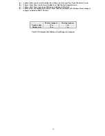
Page 10: ...res are fixed in position When the ship reaches a certain position on the screen approx 2 3 of screen size the ship is placed back to the opposite side on the screen The top of the screen faces north Note Navigation equipment such as a gyrocompass or magnet compass must be connected to your radar system before it can be operated in NU CU and TM modes Refer to Section 3 9 for details on how to conn...

Page 11: ...hat the received signal levels coming from a short distance are lowered and those from a long distance are raised This function should prove useful when there are large reflected waves from sea surfaces during rough weather FTC Fast Time Constant When it rains or snows fine noise may appear over the entire screen making it difficult to identify echoes In such a case echo images on the screen can b...

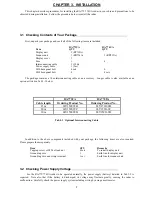
Page 12: ...in Tab 3 1 below Tab 3 1 Optional Interconnecting Cable In addition to the above components included with your package the following items are also required Please prepare them separately Item QTY Remarks Tapping screw or M5 bolt and nut 6 sets To install display unit Grounding wire 1 Earth line for display unit Grounding wire and crimp terminal 1 set Earth line for scanner unit 3 2 Checking Power...

Page 13: ...hoes install the scanner at a position nearer to the ship s bow away from obstacles When installing the scanner on a mast position it in front of the mast If obstacles cannot be avoided for the ship s structural reasons refer to Shifting away from obstacles described Page 13 d Do not install the scanner near hot or heat generating items Do not install the scanner at a position where it may be subj...

Page 14: ...id display temperature up c A place where there is good ventilation and minimum vibration d A place where the display unit is apart more than the minimum safe distance from a magnet compass as listed in Tab 3 3 below Tab 3 3 Minimum Safe Distance from Magnetic Compass Master compass Steering compass Scanner unit 2 0m 1 4m Display unit 2 0m 1 4m ...

Page 15: ...2 m when R 15m Ls 0 025R D 2 m when R 15m where Ls distance to be shifted from keel line D diameter of obstacle on keel line R distance from scanner to obstacle symbol 130 f Wingdings s 10 Obtaining sufficient dip angle Raise the scanner position so that there is a sufficient dip angle symbol 113 f Symbol s 10θ available between the line of sight from the scanner to the obstacle and the horizontal...

Page 16: ...vature of more than 2mm repair it or use spacers Referring to Fig 3 4 open holes in diameter of 12 mm 0 47 in at five locations in the mount base and use these holes to fix the scanner unit to the mount base with hexagonal bolts Use the template included with this manual The bolts included with your radar equipment will suffice for mount base thickness of 9 to 14 mm 0 35 to 0 55 in If the mount ba...

Page 17: ...rks 1 4mm 0 04 0 16 in M10 M12 symbol 180 f Symbol s 10 15 1 5mm pitch Stainless 4 9mm 0 16 0 35 in M10 M12 symbol 180 f Symbol s 10 20 1 5mm pitch Stainless 9 14mm 0 35 0 55 in M10 M12 symbol 180 f Symbol s 10 25 1 5mm pitch Stainless Included with radar 14 19mm 0 55 0 75 in M10 M12 symbol 180 f Symbol s 10 30 1 5mm pitch Stainless ...

Page 18: ... bolt length according to the thickness of the surface on which you are going to install the display unit Hole diameter is different using bolts from using tapping screw When using tapping screw open holes in adequate holes When using bolts and nuts open holes in diameter of 6 mm 0 24 in When you have opened holes install the pedestal part first and then the display unit Note When you install the ...

Page 19: ...me from the scanner unit Avoid bumping it against the antenna by lifting vertically There are four fixing screws symbol 131 f Wingdings s 10 Remove the tape fixing the antenna symbol 132 f Wingdings s 10 Remove the shield cover located on the astern side There are four fixing screws symbol 133 f Wingdings s 10 Remove the cable clamping plate and rubber ring pass cable through the introduction open...

Page 20: ...16 Fig 3 8 Fitting interconnecting cable seq Fig 22__Fitting_interconnecting_cable Arabic 1 ...

Page 21: ...ve the four bolts securing the fixing plate at the cable entrance symbol 133 f Wingdings s 10 Remove the metal fixing plate rubber seal and washer that secure the cable Pass the cable through as shown in the diagram below replace the above items and tighten the bolts symbol 134 f Wingdings s 10 Return the transceiver to its original position and secure it with the removed bolts symbol 135 f Wingdi...

Page 22: ...rounding terminal on the rear panel of the display unit to the ship s hull as shown below Connect grounding wire from one of the bolts you have attached when installing the scanner unit to the ship s hull as shown in Fig 3 11 The crimp terminal and grounding wire are not included with the radar equipment Fig 3 10 Grounding display unit to earth ...

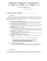
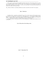
Page 23: ...onductor Cable max length cross section 12Vdc 3 5 mm2 3 m 6 0 mm2 5 m 24Vdc 2 0 mm2 6 m 3 5 mm2 10 m 3 8 Adjustment Be sure to operate the following adjustment If this is not adjusted properly the radar picture does not display true image When you have finished installing the scanner and display units and connecting cables turn on the power to the display and scanner units and check to see if they...

Page 24: ...e from Anritsu Refer to CHAPTER 8 4 External interface Junction box with OPTION cable Order No RZ704A 3 10 When Discarding Your Radar When discarding your RA773UA RA774UA radar consult Anritsu or its distributor to get information on precautions to be followed Tab 3 5 below lists the primary component materials of the RA773UA RA774UA radar for your reference Tab 3 seq Tab Arabic 5 Component Materi...

Page 25: ...21 ...

Page 26: ...sor key that lets you move a cursor in any desired direction A combination of these keys allows you to utilize all functions of your radar providing a comfortable easy way to operate 4 1 Key layout Key No SET1 SET2 SET3 SET4 1 EBL1 EBL2 RINGS PPI 2 VRM1 VRM2 TUNE PPI 3D 3 VAR RNG FL EBL2 ST PPI PPI 4 TRACK FL VRM2 ZOOM PPI NAV 5 TARGET GZ SLEEP ALL PPI 6 SEL WIN OFF C PICTURE ALL PPI2 7 NEXT NEXT ...

Page 27: ...minal to connect grounding wire Refer to Section 3 6 3 Grounding wire symbol 131 f Wingdings s 10 Option connector Use this connector to connect NMEA an external monitor external buzzer and GYRO I F A dedicated cable or dedicated module box is required to connect these pieces of equipment Refer to Section 3 8 Connecting External Equipment to Display Unit symbol 132 f Wingdings s 10 Scanner connect...

Page 28: ...24 4 4 Radar screen Dual screen ex PPI PPI screen 4 5 Radar screen All PPI screen ...

Page 29: ... your ship seawater temperature and other navigation information Note Heading angle will be displayed COG when Course Over Ground data is used Note Cruising speed will be displayed SOG when Speed Over Ground data is used Indicates starboarding the helm right Indicates porting the helm left Deviation from Indication mark 0 00 0 02 or 0 04 or 0 08 or 0 16 or Tab 6 Indication of deviation from course...

Page 30: ...g off Keep pressing the POWER key more than 3 seconds then the radar system will power off 5 2 Adjusting contrast and brilliance of the screen and key backlight 1 Press the BRILL key Bar indicating contrast brilliance and key backlight appears on the screen 2 Adjust each items with the control knob Items can be selected by up down cursor 3 When the adjustment is finished press either the BRILL key...

Page 31: ...x Control knob Adjust brilliance with knob key backlight eq x Up Down Select key backlight eq x Control knob Adjust key backlight with knob eq x ENT Press ENT key to return Radar turn into ST BY mode when 2 minutes timer is finished and ST BY displayed 5 3 2 Transmitting eq x POWER Press POWER key to operate radar picture appears on the screen Another press POWER key radar turn to stand by mode Ke...

Page 32: ...nge RANGE UP RANGE DOWN Pressing RANGE UP key produces a long distance range and RANGE DOWN key a short distance range RADOME SCANNER RANGE 0 125 0 25 0 5 0 75 1 5 3 6 12 24 36 Number of rings 2 2 2 3 6 6 6 6 6 6 Range ring interval 0 0625 0 125 0 25 0 25 0 25 0 5 1 2 4 6 OPEN SCANNER RANGE 0 125 0 25 0 5 0 75 1 5 3 6 12 24 48 Number of rings 2 2 2 3 6 6 6 6 6 6 Range ring interval 0 0625 0 125 0 ...

Page 33: ...n will take place a To make adjustments by MANUAL When the GAIN key is pressed under AUTO operation shift to a manual operation will take place eq x GAIN eq x Control knob eq x GAIN The adjustment state is ended eq x Other function key Shift to other functions eq x AUTO eq x AUTO GAIN STC and FTC are set at AUTO and the adjustment state is ended b To switch from the MANUAL state eq x AUTO Set GAIN...

Page 34: ...to exit from the adjustment state If some other function key is pressed shift to that function will take place a To make adjustments by MANUAL When the FTC key is pressed under AUTO operation shift to a manual operation will take place eq x FTC eq x Control knob eq x FTC The adjustment state is ended eq x Other function key Shift to other functions eq x AUTO eq x AUTO GAIN STC and FTC are set at A...

Page 35: ...q x 1 xxx x indicates EBL1 eq x EBL1 eq x Control knob eq x EBL1 EBL1 is displayed and the process is finished eq x Other function key EBL1 is displayed and the function is shifted eq x EBL1 EBL1 is turned off b b To turn off the EBL1 When the EBL1 key is pressed twice EBL1 disappears EBL1 OFF Note Please refer to 5 5 1 1 Bearing measurement EBL1 5 4 2 Bearing measurement EBL2 The operation is the...

Page 36: ...EBL2 key SET START POINT is displayed and a small cross mark appears eq x FL EBL2 FL EBL2 is turned ON and Select FL EBL2 the small cross mark appears 2 Use the left right and up down cursor keys to place the small cross mark on one of the two echoes whose angle will be measured and press the ENT key eq x Up Down eq x Left Right eq x ENT Criterion of the reference point is set Place the cross curs...

Page 37: ...t will be the distance between the two points 5 4 7 Changing the group of Soft Keys NEXT Any function can be optionally allocated to the key upon which numbers 1 7 are indicated A maximum of 4 groups of functions can be allocated to each soft key and switching between those functions is conducted by the NEXT key The NEXT key switches between allocated function groups on the soft key which numbers ...

Page 38: ...NG function is on and it changes in steps with the RANGE UP or RANGE DOWN keys If pressing other keys return to the normal state from continuously range change state 5 4 12 Changing display modes MODE 1 Select MODE from the pull down display items using the up down cursor keys and press either the ENT key or the Right key 2 When the HU HS NU CU TM sign is displayed beside the MODE item select disp...

Page 39: ...eft Right eq x ENT Setting completed Setting the center of GZ Setting the scope of GZ eq x GZ Canceling GZ Stop the alarm tone Press the MENU key or ENT key during the alram tone sounds alarm tone will stop note Set the mode IN or OUT at the GZ MODE of the PRESET2 function in the CUSTOM menu of the SETUP Set the alarm level IN or OUT at the GZ LVL of the PRESET2 function in the CUSTOM menu of the ...

Page 40: ...en at the fixed time another 30 second transmission begins This series of actions are repeated If any one key is pressed during the course of this action the SLEEP function will be canceled Note Please refer to 5 5 2 4 Setting of the SLEEP function SLEEP 1 Setting procedure eq x SLEEP Select 5min eq x ENT eq x POWER 30 second transmission every 5 min transmission ON eq x SLEEP Select 10min eq x EN...

Page 41: ...ndicates the length of the track and displays a maximum of 15 second long sailing track Note Please refer to 5 5 3 6 Displaying locus of target TRACK Every time this key is pressed the course length switches as follows 15sec30sec 1min3min 6min CONT OFF Note The OFF state will not displayed on the screen and the TK xx display will disappear 5 4 19 Enlarging selected areas ZOOM The video image cente...

Page 42: ...Select SHORT Set to short pulse or Select LONG Set to long pulse 5 4 21 Switching the screen SEL WIN Switching to the desired screen for activation on a 2 screen display PPI PPI When change the range or adjust the GAIN STC or FTC or control the VRM EBL select the desired screen first ex To be used for switching the range on the PPI PPI screen When the SEL WIN key is pressed the range of the select...

Page 43: ...y the screen will change to PPI PPI screen Use to change the screen from other modes to PPI PPI Note 1 The radar picture is refreshed with two scanning interval for each screen Right screen picture is holded during refreshing left screen left screen holded during refreshing right screen LEFT screen ime ROGHT screen 2 The ZOOM OFF C FL EBL2 and FL VRM2 could not be used on this mode 3 The range GAI...

Page 44: ...e displayed on the upper left of the screen 2 Return to PPI screen mode pressing a key except MENU range UP or DOWN or POWER key 5 4 28 Change to ALL PPI PPI screen ALL PPI2 Press the ALL PPI2 key the screen will change to ALL PPI PPI screen Use to change the screen from other modes to ALL PPI PPI Note 1 The range rings interval display mode are displayed on the upper left of each screen 2 Return ...

Page 45: ... SUB MENU PRESET2 SUB MENU ADJUST SUB MENU CSR ON OFF ZOOM ON OFF RINGS ON OFF PL S L VAR RNG ON OFF TARGET MK LINE ON OFF List of Custom Menu PRESET1 SUB MENU PRESET2 SUB MENU HM FLSH ON OFF GZ LEVEL 17 STERN M ON OFF GZ MODE IN OUT NORTH M ON OFF HOLD ON OFF ST BY DISPLAY NAV RDR DISPLAY RDR MONI NAV BUZ VOL HIGH LOW OFF EXT BUZ OFF CONT INT RM UNIT NM KM SM IN P R 360 1024 2048 4096 DEPTH M FT ...

Page 46: ...r the ENT key 2 When the ON OFF sign is displayed beside the EBL1 item select ON with the up down cursor keys and press the ENT key 3 When the ENT key is pressed electric bearing lime EBL1 appears and the angle from the direction of the ship s head which is set at 0 degree will appear in a reverse display at the lower left of the screen 4 Place the marker on the center of the target with the contr...

Page 47: ...nction of that key with the VRM1 display still on the screen eq x Up Down eq x ENT eq x Up Down eq x ENT eq x Control knob eq x ENT a Select VRM1 Select ON VRM1 operation eq x MENU b eq x Other function key c Note eq x 1 NM indicates VRM1 5 5 1 3 Bearing measurement EBL2 Refer to the section Bearing measurement EBL1 The EBL2 will appear in a reverse display at the lower right of the screen Note eq...

Page 48: ...nts Note EBL2 and VRM2 are not follow to ZOOM and OFF C function 5 5 1 6 Measuring the angle between two points FL EBL2 a Preparation for the measurement 1 Use the up down cursor keys to select FL EBL2 from among the pull down display items and press either the ENT key or the right cursor key 2 Use the up down cursor keys to select ON from the ON OFF display beside the FL EBL2 items and press the ...

Page 49: ... key to select HDG OFF from among the pulled down and displayed items 2 Press the ENT key The heading maker is not displayed as long as you hold it down eq x Up Down eq x ENT The heading maker is not displayed as long as you hold ENT key down Select HDG OFF 5 5 1 8 Using parallel cursors CSR Normally EBL is used to measure the exact bearing from the position of your ship to a target However you ca...

Page 50: ...own Select OFF eq x ENT Range rings non appears Number of range rings and range interval Radome antenna Range 0 125 0 25 0 5 0 75 1 5 3 6 12 24 36 Number of Rings 2 2 2 3 6 6 6 6 6 8 Interval 0 062 5 0 125 0 25 0 25 0 25 0 5 1 2 4 4 Open antenna Range 0 125 0 25 0 5 0 75 1 5 3 6 12 24 48 Number of Rings 2 2 2 3 6 6 6 6 6 8 Interval 0 062 5 0 125 0 25 0 25 0 25 0 5 1 2 4 6 5 5 1 10 Variable range f...

Page 51: ...ct TARGET from among the pull down display items and press the ENT key The L L data of the position will be output to NMEA port with TLL format eq x Up Down eq x output the L L position of the cursor Select TARGET Note When activate this function nothing happened on the screen 5 5 1 12 Follow the Distance and Bearing marker on the cursor MK LINE 1 Use the up down cursor keys to select MK LINE from...

Page 52: ...48 ...

Page 53: ...cursor key and press either the ENT key 2 When the MODE sign is displayed beside the MODE item select a mode with the up down cursor keys and press the ENT key 3 The display mode indicates upper left on the screen eq x UP DOWN eq x eq x UP DOWN Select MODE Select HU eq x Head up Select HS eq x Head set Select NU eq x North up Select CU eq x Course up Select TM eq x True motion Note1 Navigation equ...

Page 54: ... setting state 3 Use the up down and left right cursor keys to move the cross cursor to the center of the warning zone to be set and press the ENT key 4 From the cross cursor position set in 2 above as the center expand the guard zone in the 5 After the setting the guard zone finish by pressing the ENT key To cancel the guard zone function select OFF by common operation for the GZ menu and press t...

Page 55: ...sor keys and press the ENT key 3 OFF C is displayed at the upper right and SET OFF CENTER POINT at the bottom of the screen and setting is ready to be entered Move the cross cursor with the cursor keys to move the ship s to the intended location and press the ENT key The ship s location will be displayed at the cursor s location The display at the upper right will be normalized from the reverse st...

Page 56: ...pressed during the course of this action the SLEEP function will be canceled a Setting procedure eq x Up Down eq x ENT eq x Up Down Select OFF eq x ENT SLEEP function is turned OFF Select SLEEP Select 5min eq x ENT eq x POWER 30 second transmission every 5 min Select 10min eq x ENT eq x POWER 30 second transmission every 10 min Select 15min eq x ENT eq x POWER 30 second transmission every 15 min T...

Page 57: ...peration for the ECHO menu has already been completed 5 5 3 1 Sensibility adjustment GAIN 1 Use the up down cursor keys to select GAIN from among the pull down display items and press either the ENT key or the right cursor key 2 Select MANU from the MANU AUTO display beside the GAIN item using the up down cursor keys and press the ENT key 3 The present state of GAIN is displayed in reverse on the ...

Page 58: ...eq x ENT eq x Control knob eq x ENT Set to MANU mode FTC adjustment Select AUTO eq x ENT Set to AUTO mode 5 5 3 4 Adjusting receiver tuning TUNE Refer to the section Sensibility adjustment GAIN eq x Up Down eq x ENT eq x Up Down Select TUNE Select MANU eq x ENT eq x Control knob eq x ENT Set to MANU mode TUNE adjustment Select AUTO eq x ENT Set to AUTO mode 5 5 3 5 Echo expansion ST Expanding the ...

Page 59: ...3 7 Enlarging selected areas ZOOM The video image centering around the cross cursor is doubled as it is displayed on the screen 1 Use the up down cursor keys to select ZOOM from among the pull down display items and press the ENT key 2 Select ON the using up down cursor keys from the ON OFF display beside the ZOOM item and press the ENT key 3 A small cross cursor for setting and SET ZOOM POINT are...

Page 60: ...on during a floating state Note 2 Normal screen returns when you change the range scale Note 3 ZOOM function is usable only in PPI screen Note 4 ZOOM function is unusable in OFF C Note 5 Center of ZOOM can be set any desired position within the set range ...

Page 61: ...ensitivity and shows targets in large size for easy identification although distance resolution is reduced 1 Use the up down cursor keys to select S L from among the pull down display items and press the ENT key 2 Select Pulse length SHORT or LONG using the up down cursor keys from the SHORT LONG display beside the S L item 3 The setting will be completed when the ENT key is pressed after the sele...

Page 62: ...n for the SETUP menu has already been completed 5 5 4 1 Initiating the screen display WINDOW A function to switch the display method of the screen A selection can be made from among the 7 patterns of screen arrangements from the ordinary PPI display to the 2 screen PPI display etc a PPI screen b PPI screen SEMI3D screen c PPI screen PPI screen Range can be operate in each screen d PPI screen Navig...

Page 63: ...reen SCREEN ITEM PPI SEMI3 D PPI NAV PPIPPI ALL PPI ALL PPI PPI MOB RANGE VRM1EBL1 VRM2EBL2 FL VRM2EBL2 RINGS ON OFF ZOOMOFF CENT CSR HDG OFF STERN M NORTH M GAINSTCFTC TUNE ST GZ SEL WIN CONTRAST TXON OFF Independent control at time as two screen Switching the screen is necessary SEL WIN It becomes simultaneous control at the time as two screen It can be used only at the time of PPI screen It can...

Page 64: ...ected screen Operation a Changing RANGE of LEFT screen When the RIGHT range indicator displayed in reverse change to LEFT screen with SEL WIN function Press RANGE UP or RANGE DOWN key to change the LEFT screen RANGE b Adjusting GAIN of LEFT screen When the RIGHT range indicator displayed in reverse change to LEFT screen with SEL WIN function Press the GAIN key G 55 will displayed in reverse and re...

Page 65: ...and Display mode are displayed on the upper left of the screen Note2 When press the key except MENU RANGE UP DOWN BRILL and POWER return to PPI screen f ALL PPI PPI Screen Note1 The RANGE RINGS interval and Display mode are displayed on the top of the screen Note2 When press the key except MENU RANGE UP DOWN BRILL and POWER return to PPI PPI screen g MOB Screen The MOB key has been pressed the MOB...

Page 66: ...Reversing the screen PICTURE Reversing to the screen for easy viewing on weather temperature and day night environment conditions When PICTURE is selected with the up down cursor keys from among the pull down display items select DAY and the ENT key is pressed a normal display will appear A reverse display will appear if NIGHT selected eq x Up Down eq x eq x Up Down select DAY eq x normal display ...

Page 67: ...it and its voltage value at video circuit normally about 5 V hHigh voltage at SU Indicates the status of th high voltage supplied from the display unit to the scanner unit and its voltag value normally about 250 V at scanner unit iHigh voltage at DU Indicates the status of th high voltage supplied from the display unit to the scanner unit and its voltag value normally about 250 V at display unit j...

Page 68: ... the common operations for the SETUP menu and press either the ENT key eq x MENU eq x Left Right eq x Up Down eq x ENT Select SETUP Select CUSTOM Common operation for SETUP When the above operations have been conducted 4 items namely KEY ASSIGN PRESET1 PRESET2 and ADJUST are displayed beside the CUSTOM item Further explanation concerning the CUSTOM menu items will be done on the assumption that th...

Page 69: ...l be canceled The current settings for SET1 4 will be displayed below NEXT In order to switch the settings SET1 4 use the right left cursor keys Double settings setting 1 item for more than 1 key are possible When settings are to be conducted for more than 1 key repeat the operations 3 1 to 3 2 Example 3 4 Completing the setting After the setting has been finished press the ENT key to exit from KE...

Page 70: ...from Select HDG OFF The display beside key 6 ST to HDG OFF changes to HDG OFF eq x Left Right eq x Up Down eq x eq x ENT Key Select SEL WIN SEL WIN is displayed Exit fromis altered to SEL WIN From SET1 beside key 1 KEY ASSIGNMENT to SET2 ...

Page 71: ...reen Setting the screen display in stand by NAVI Navigation Data screen NOR Normal screen e Buzzer Volume Setting the volume of the buzzer VRM Unit Setting VRM unit NM Nautical mile KM Kilometer SM Statute mile g Water temperature Setting water temperature unit C Celsius F Fahrenheit h Depth Unit Setting Depth unit M Meter FT Feet FM Fathom i EBL Mode Setting Mode of EBL REL Relative bearing from ...

Page 72: ...0 1 LONG 0 0 1 1 2 P TABLE 1 SHORT 0 0 0 1 1 LONG 0 1 1 2 2 P TABLE 2 SHORT 0 0 1 1 1 LONG 1 1 2 2 2 Note1 Pulse width 0 0 08uS 1 0 25uS 2 0 8uS Note2 The pulse width for 0 125 to 0 25NM Ranges are always 0 08us Note3 The pulse width for 12NM to 36 48 NM Ranges are always 0 8us ...

Page 73: ...OLD state Note1 d Display Unit Mode Display Unit Operation Mode setting RDR Radar mode normal MONI Monitor mode for slave display use NAV Navigation mode for DATA indicator use e External Buzzer External Buzzer control setting OFF Buzzer off CONT Continuous tone INT Intermittent tone f Bearing pulse rot IN Change the setting when connected to the other type of radar g Bearing pulse rot OUT Change ...

Page 74: ...LD is function which you want to hold the currently displayed radar screen conditions while standby state After finished operation such as EBL VRM about 30 seconds the screen return to standby screen Setting HOLD eq x POWER Operation Under Tx Under HOLD modeST BY DISPLAY Turn to transmissin off EBL VRM operation seconds 30seconds Time used NOTE EBL and VRM function is usable in HOLD state Note2 15...

Page 75: ...rol knob If there is a linear target such as a bridge or breakwater adjust timing until the target appears straight in the screen 2 3 When the adjustment is finished press the ENT key to exit from the distance adjustment screen eq x Up Down eq x ENT eq x Control knob eq x ENT select TIMIG ADJ Timing adjustmentfinished 2 Adjusting angle HEAD ADJ This adjustment is necessary to adjust the head direc...

Page 76: ...ny symptom suggesting improper tuning you may need to adjust this circuit following the procedure below 1 Choose several stable video images in the 3 NM range or more 2 Select ADJUST by common operations for CUSTOM use the up down cursor keys to select TUNING CAL from among the pull down display items and press the ENT key 3 As the tuning circuit adjustment screen TUNING CALIBRATION is displayed s...

Page 77: ... from among the pull down display items and press the ENT key 2 As the adjustment screen is displayed using up down key to choose your desired value from 1 to 9 3 Press the ENT key to exit from the adjusting antenna height screen eq x Up Down eq x ENT eq x Control knob eq x ENT Select ANTENNA Choose value Complete 5 Setting automatic GAIN circuit AUTO GAIN Here you set the automatic and manual gai...

Page 78: ...tting automatic STC circuit AUTO STC Here you set the automatic STC and automatic FTC level Adjust this setting to be slight sea clutter appears on the screen when you observe a small target ex Small buoy 1 Select ADJUST by common operations for CUSTOM use the up down cursor keys to select AUTO STC from among the pull down display items and press the ENT key 2 As the adjustment screen is displayed...

Page 79: ...ck light This part is mounted in the display unit If the display screen is extremely dark and its illumination cannot be corrected by adjusting brightness the LCD back light may be faulty or may have burnt out In such a case replace it Consult your distributor for replacement of this part Period of the replacement 15000hour typ 1000hour at 0 3 Fuse The fuse is built in the power supply cable If th...

Page 80: ...76 Note Before maintenance of scanner you can hang a radome upper using cord through hole as follows Fig 6 3 Method for replacing fuse ...

Page 81: ...ring number indicated on the back of the display unit 4 Fault symptoms and inspection results There are high voltage circuit inside of this radar Do not attempt to open the rear cover of display unit or disassemble internal parts When you open the radome for installation power must be off Even power switch is OFF this radar is still supplied power inside This chapter explains how to identify troub...

Page 82: ...oes not appear although characters are displayed Interconnecting cable is out of place Connect interconnecting cable correctly 5 Echo image on screen differs from actual image Ship s heading is incorrectly set Set ship s heading correctly See Section 5 5 4 5 4 Timing adjustment is incorrectly set Set timing adjustment correctly See Section 5 5 4 5 4 6 Echo images are blurred GAIN STC or FTC is imp...

Page 83: ... of the scale in use or 8m whichever is the greater Minimum detecting distance Within 25 m Bearing resolution Within 4 5symbol 176 f Symbol s 10 RA773UA Within 3 0symbol 176 f Symbol s 10 RA774UA Bearing accuracy 1symbol 176 f Symbol s 10 or less Warm up time 2 minutes Environment conditions Ambient temperature range S U 25 to 55 symbol 176 f Symbol s 10 C D U 0 to 55 symbol 176 f Symbol s 10 C Hu...

Page 84: ...80 Interconnecting cable 100 m max Noise D U 65 dB or less S U 65 dB or less RA773UA S U 75 dB or less RA774UA ...

Page 85: ...4UA with 3 4ft antenna Pulse width 0 11 0 02 us 0 25 0 05 us 0 8 0 1 us peak power output 4 kW 20 50 Radio wave type and frequency P0N 9410 symbol 177 f Symbol s 10 30 MHz Antenna revolution 24 rpm symbol 177 f Symbol s 10 20 Transmit receive switching Circulator and limiter type Intermediate frequency 60 MHz logarithmic amplifier Noise figure 6 5 dB or less typ 8 3 Display Unit Type RF718A Indica...

Page 86: ... Navigation data display mode Panel brightness 4 levels Language support Chinese Danish English French German Greek Italian Japanese Korean Norwegian Portuguese Russian Spanish Swedish and Turkish 8 4 External Interface NMEA0183 2 channels One standard channel Optional cable is required for 2nd channel connections L L GGA GLL RMA RMC Heading HDT HDG HDM HSC VHW VTG Speed VHW VTG RMA RMC Way point ...

Page 87: ...Fuse 1 set Interconnecting cable 1 10m Power supply cable 1 2m M10 M12 hexagonal bolt 4 sets 8 6 Options Interconnecting cable 15 20 and 30 m Flush mount installation kit Junction box for external connection with cable 1 5m Option connector kit 249J153058 8 7 External dimensions and weight See APPENDIX ...

Reviews: