background image


L

A N

B

O Y  

A

I R


T

HE 

M

OST 

M

ODULAR

,


M

OST 

C

USTOMIZABLE 

O

PEN

-

AIR 

C

HASSIS


U

S E R    

M

A N U A L


All manuals and user guides at all-guides.com

all-guides.com

Summary of Contents for Super LANBOY

Page 1: ...L A N B O Y A I R THE MOST MODULAR MOST CUSTOMIZABLE OPEN AIR CHASSIS U S E R M A N U A L All manuals and user guides at all guides com a l l g u i d e s c o m...

Page 2: ...a power supply Make sure you choose a power supply that is compatible with your computer components and has a long enough power harness to reach your motherboard and peripheral devices We recommend o...

Page 3: ...rboard PSU 13 2 6 Motherboard Installation 15 2 7 Power Supply Installation 17 2 8 Cable Management 17 SECTION 3 FRONT I O PORTS 3 1 USB 2 0 19 3 2 USB 3 0 19 3 3 AC 97 HD audio ports 19 3 4 Front Pan...

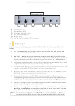
Page 4: ...4 INTRODUCTION SECTION 1 All manuals and user guides at all guides com...

Page 5: ...supply mount 3 2 5 internal SSD bay 12 Front I O ports 4 Built in toolbox for spare screws parts 13 8 expansion slots Cooling 5 2 x 120 mm top fan mounts and water cooling radiator fitting 6 1 x 120...

Page 6: ...B 3 0 2 x USB 2 0 AC 97 HD Audio In and Out 1 3 INCLUDED SCREWS The LanBoy Air is designed to be extremely flexible A variety of screws are included to accommodate the multitude of configurations that...

Page 7: ...a connector or screw on the back of this computer or by using a wrist grounding strap Before you connect a cable ensure that both connectors are correctly aligned and oriented Bent pins can be diffic...

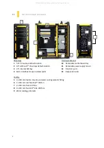
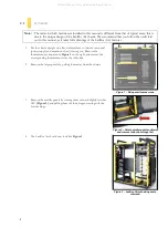
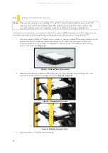
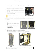
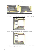
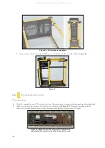
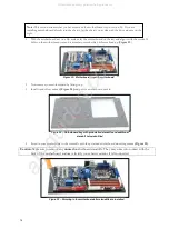
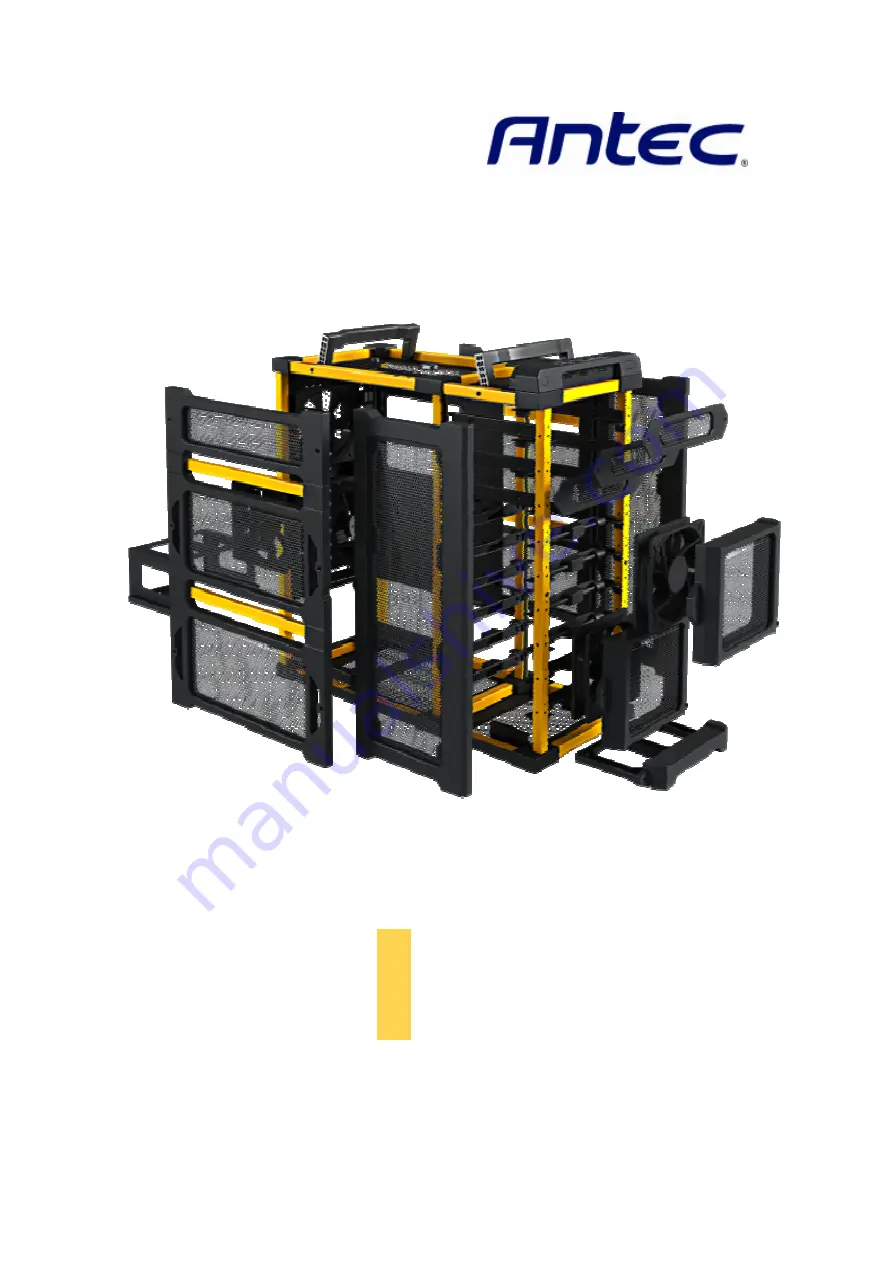
Page 8: ...8 HARDWARE INSTALLATION SECTION 2 All manuals and user guides at all guides com...

Page 9: ...ng them off their hinges starting with the bottom hinge 4 The LanBoy Air should now look like Figure 3 Note The order in which hardware is installed in this manual is different from that of typical ca...

Page 10: ...ttom of the bracket is flush with the bottom of the hard drive Figure 4 2 Determine the horizontal orientation of the drive you wish to use and attach the mounting hooks to the attachment openings clo...

Page 11: ...sure to install the mounting rails based on the orientation you would like to use Figure 8 Figure 9 3 Slide the drive into the drive bay and secure it to the mounting rails using four 5 25 external m...

Page 12: ...ils themselves can be relocated to accommodate top mounting the PSU Removing the PSU Mount 1 Place the chassis upright with the front facing right 2 Remove the left larger panel 3 Remove the thumb scr...

Page 13: ...13 4 Remove the four screws holding the PSU mount in place Lift and remove the mount moving it towards the front of the chassis Figure 18 All manuals and user guides at all guides com...

Page 14: ...l the rails in the lower slots indicated in Figure 20 and secure using the screws you just removed 7 Install the PSU mount at the top of the chassis flipping the PSU mount and installing screws in the...

Page 15: ...e installing the motherboard Make sure you have the correct I O panel for your motherboard Figure 23 If the panel provided with the chassis isn t suitable please contact your motherboard manufacturer...

Page 16: ...ove any unused motherboard standoffs They may come into contact with the back of the motherboard and may electrify your chassis exterior if left connected Note This section assumes that you have remov...

Page 17: ...to the PSU mount with the screws provided Figure 27 2 Insert the PSU mount with PSU into the chassis along the rails Secure the PSU mount with the thumbscrew 3 Connect the PSU connectors to your devi...

Page 18: ...anel You may also need to remove the smaller side panel depending on the horizontal orientation of your drives 2 Choose the cables you would like to pass through the open sections to behind the mother...

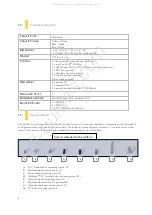
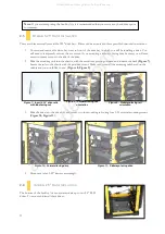
Page 19: ...19 FRONT I O PORTS SECTION 3 All manuals and user guides at all guides com...

Page 20: ...manual to ensure that it matches the table below 3 2 USB 3 0 There is a USB 3 0 connector in the front I O panel To use this connector please refer to the instruction sheet included with the chassis 3...

Page 21: ...Attach these to the corresponding connectors on your motherboard Consult your motherboard manual for specific pin header locations For LEDs colored wires are positive White or black wires are negativ...

Page 22: ...er to rewire your plug to match the USB pin outs on your motherboard refer to your motherboard user s manual Working on one connector at a time use a very small flathead screwdriver or similar tool to...

Page 23: ...23 COOLING SYSTEM SECTION 4 All manuals and user guides at all guides com...

Page 24: ...0 MM TWOCOOL LED FANS The LanBoy Air comes with one rear and two side 120 mm TwoCool LED fans These fans have a two speed switch that lets you choose the speed best suited to your need The rear fan sw...

Page 25: ...ontrol fan Rated Voltage 12V DC Operating Voltage 10 8V 13 2 V Speed Input Current Air Flow Static Pressure Noise Input Power Highest 2000RPM 0 3A 1 9m min 66 6 CFM 2 6 mm H2O 0 1inch H2O 34 5 dBA 3 6...

Page 26: ...he top fan mounting screws identified in section 1 3 When installing optional side mounted fans use the side fan mounting screws identified in section 1 3 4 5 WATER COOLING The LanBoy Air is water coo...

Page 27: ...31 0 10 437 1752 Technical Support US Canada 1 800 22ANTEC customersupport antec com Europe 31 0 10 462 2060 europe techsupport antec com www antec com Copyright 2010 Antec Inc All rights reserved Al...

Reviews: