background image

Measure
what is measurable
and make measurable
that which is not.

Galileo Galilei (1564-1642)

Instruction Manual and Safety Information

DHS 1100

Domed Hot Stage with 

CCU 100 Control Unit

(Original Instruction)

Summary of Contents for DHS 1100

Page 1: ...easure what is measurable and make measurable that which is not Galileo Galilei 1564 1642 Instruction Manual and Safety Information DHS 1100 Domed Hot Stage with CCU 100 Control Unit Original Instruction ...

Page 2: ......

Page 3: ...uding translation This document or any part of it may not be reproduced changed copied or distributed by means of electronic systems in any form print photocopy microfilm or any other process without prior written permission by Anton Paar GmbH Trademarks registered trademarks trade names etc may be used in this document without being marked as such They are the property of their respective owner F...

Page 4: ...eration 19 4 1 Alignment 19 4 2 Starting CCU 100 19 5 Operating CCU 100 20 5 1 Front Panel of the Instrument 20 5 2 Keypad 20 5 3 Display 21 5 4 Turning the Heater On and OFF 22 5 5 Controlling the Compressed Air Cooling 23 5 6 Manual Control of CCU 100 23 5 7 Remote Control of CCU 100 23 6 Operation 24 6 1 Preparing the Instrument 24 6 2 Mounting the Sample 24 6 3 Mounting and Removing the Dome 2...

Page 5: ...nt safely and correctly before starting any applicable operations In case of damage or malfunction do not con tinue operating DHS 1100 Do not operate the instrument under conditions which could result in damage to goods and or injuries and loss of life Check DHS 1100 for chemical resistance to the samples and cleaning agents Maintenance and service The results delivered by DHS 1100 not only depend...

Page 6: ...e situation at hand WARNING Description of risk Warning indicates a hazardous situation which if not avoided could result in death or serious injury CAUTION Description of risk Caution indicates a hazardous situation which if not avoided could result in minor or moderate injury NOTICE Description of risk Notice indicates a situation which if not avoided could result in damage to property CAUTION H...

Page 7: ...rface Fig 1 Position of warning signs on the instrument CAUTION Hot surface This symbol calls attention to the fact that the respective surface can get very hot Do not touch this surface without adequate protective measures 1 NOTICE Take care that the warning symbols remain clearly legible ...

Page 8: ...00 attachment is achieved by using com pressed air The cooling air supply is controlled with the CCU 100 Combined Control Unit The CCU 100 monitors if sufficient cooling air is available and au tomatically turns on the cooling air if the heater tem perature exceeds 200 C Below 200 C heater temperature the instrument can be run without dome and without cooling air The main applications for the DHS ...

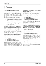
Page 9: ... on the cooling air when the heater tem perature reaches 200 C In order to achieve the maximum movability of the DHS 1100 on the goniometer the number of hoses to the instrument is kept to a minimum Besides the hose for the cooling gas there is only one additional hose 5 which contains the electrical wires for ther mocouple and heater and which is used to evacuate the dome or to fill it with gas 2...

Page 10: ... the sur rounding atmosphere The heating plate of the DHS 1100 is made of alu minium nitride AlN a ceramics with excellent tem perature conductivity and good chemical resistance In case of damage the sample plate can be easily replaced by a new one The springs for fixing the sample are made of Inco nel and can be loosened very easily by using twee zers TIP For a diffractogram of aluminium nitride ...

Page 11: ... or the gas supply Fig 5 Connection device 1 Supply hose with wires to thermocouple and heater 2 Connector for thermocouple 6 poles 3 Connector for heating 4 poles 4 Flange for gas supply vacuum pump DN16KF 2 3 CCU 100 Combined Control Unit CCU 100 is designed to control the sample plate temperature in DHS 1100 and to guarantee safe op eration of the entire instrument In order to reach and maintai...

Page 12: ...is required depending on the configura tion this could be dSP 1 C or 200 C see Chapter 5 a valve inside CCU 100 connects the AIR IN to the AIR OUT connector which is connect ed to the quick coupling connector for cooling air supply at the DHS 1100 Fig 2 1 4 In case that no cooling is required the valve be tween AIR IN and AIR OUT closes 2 3 4 Overheat Protection DHS 1100 has a protective thermoswi...

Page 13: ...g pressure and purity Anton Paar GmbH recommends to use the following pres sure regulator with filters Air Service Unit cat no 6931 Fig 8 Air service unit 1 air pressure regulator 2 air pressure gauge 3 coarse filter cartridge 4 fine filter cartridge For further details see Chapter 5 5 Controlling the Compressed Air Cooling 2 3 4 1 ...

Page 14: ...ents Optional Vacuum equipment requirements Pumping speed acc DIN 28400 4 2 m3 h Ultimate partial pressure acc DIN 28400 1E 4 mbar Ultimate total pressure acc DIN 28400 2E 3 mbar Vacuum connector on sample chamber DN16 ISO KF 3 2 Unpacking the Instrument TIP Anton Paar GmbH gives no warranty for the dome if it is not handled according to our instruc tions If the dome is already broken when unpacki...

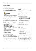
Page 15: ...0 Install the compressed air cooling device on the sample chamber as follows Connect the compressed air supply to CCU 100 1 Connect the female connector of the pneumatic hose supplied with CCU 100 to the AIR INLET connector on the rear panel of CCU 100 2 Connect the Air Service Unit to the compressed air supply of the laboratory 3 Connect the male connector of the pneumatic hose to the outlet of t...

Page 16: ...KF 8 Vent valve DN10KF The connection device for the gas supply vacuum equipment is described in chapter 2 2 4 Connection Device TIP For further information about operation of the DHS 1100 under vacuum or various gases please refer to chapter 6 5 2 Creating a Sample Environ ment 3 6 Installing the CCU 100 Combined Control Unit CCU 100 Combined Control Unit is prepared for rack mounting in a 19 4HE...

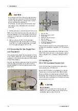
Page 17: ...ection device of DHS 1100 The tempera ture sensor cable contains the wires for the type S thermocouple measuring the sample tem perature inside the DHS 1100 and the wires for the thermoswitch which protects the DHS 1100 housing from being overheated Connect the electrical cables to the CCU 100 rear panel as follows 1 Connect the side with the cable holder to the connector sensors heater on the rea...

Page 18: ... helium 25 to 900 C with air nitrogen vacuum 25 to 750 C with helium Heating rate max 300 C min max 300 C min Cooling air pressure min 2 5 max 4 bar rel min 2 max 4 bar rel All other specifications are the same as for DHS 1100 with graphite dome CAUTION For operation of DHS 1100 with PEEK dome the cooling nozzle must be mounted properly If possible limit the range for the temperature set point to ...

Page 19: ... for a few seconds After a few seconds the micro controller switches to the normal mode of operation CCU 100 is in the following status the temperature set point SP is set to the default value of 25 C the HEATER is off the Error LED is flashing 2 Check whether the correct Cooling Type param eter is set as described in Chapter 5 3 cON turns the compressed air cooling on off at a temperature of dSP ...

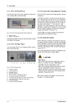
Page 20: ... manual that was delivered with the instru ment 5 1 Front Panel of the Instrument The front panel of CCU 100 contains the keypad the status LEDs and the display which are described in the following section Fig 5 1 Front panel of CCU 100 5 2 Keypad The keypad of CCU 100 has 6 keys to select param eters and enter values Fig 10 Keypad of CCU 100 5 2 1 Status LEDs There are three types of status LEDs ...

Page 21: ... The display in this case contains infor mation about the number of errors that are currently active and also the corresponding error code This is shown in the following way XExy X number of actual active errors E indicates an error xy corresponding error code By pressing the UP DOWN button it is possible to switch between all active error codes The complete list of all possible errors is shown in...

Page 22: ...ng is switch ed on above dSP 1 C when cooling to a lower set point tem perature Cooling of the housing is always active above 200 C cOFF Cool ing of the housing is only switched on at tem peratures above 200 C GrA d PE d Configuration for graphite dome and PEEK dome Limits the operating tem perature depending on the used dome Graphite dome max 1100 C PEEK dome max 900 C OP shows the actual heating...

Page 23: ... the desired heating cooling rate on the parameter page of CCU 100 See Chapter 5 3 1 3 Push the scroll button one time SP LED green and set the desired target temperature by using the UP DOWN buttons 4 Wait until the displayed sample plate tempera ture has reached the target value TIP If you have chosen a large heating cooling rate wait 1 minute before you start the X ray scan to make sure the sam...

Page 24: ...e recommended sample diameter is 15 20 mm and the recommended sample thick ness is 1 mm This ensures good clamping of the sample to the heating plate and maximum tempera ture homogeneity across the sample The sample is fixed on the sample plate with springs The springs are supplied in the accessory box and can be easily exchanged by pulling them out of the small bore holes Depending on the sam ple...

Page 25: ...nce guide C58IB002EN Fig 6 1 Powder Sample Carrier PSC Fig 15 PSC with Anti Scatter slit ASS Both the powder sample carrier cup depth 1mm cup diameter 15 mm and the anti scatter slit are made of Inconel Two different heights of the anti scatter slit are available 0 5 mm and 1 mm Mounting without Anti Scatter Slit 1 Put the PSC in the middle of the heating plate 2 Fix the PSC with the short 5 mm fi...

Page 26: ... on the CCU 100 We recommend to carry out a temperature validation measurement to determine this deviation before starting with the actual experiments 6 2 3 Sample Temperature Be aware that depending on the sample thickness and the thermal conductivity of the sample the tem perature of the heating plate will be different from the temperature of the sample surface The temperature gradients across t...

Page 27: ...sen the 3 screws using the screw driver from the accessory box 4 Take the dome by the fixing ring and turn it until the three clasps are free 5 Lift the dome off the housing 6 4 Operation of DHS 1100 with PEEK Dome For operation with a PEEK dome the dome cooling nozzle or the HT dome cooling nozzle must be mounted When you operate DHS 1100 with a graphite dome remove the dome cooling nozzle and mo...

Page 28: ...o the DHS 1100 refer to chapter 3 4 Installing the Compressed Air Cooling If the PEEK dome is required make sure that the dome cooling nozzle is installed see chap ter 3 8 Installing the Cooling Nozzle 6 5 2 Creating a Sample Environment With DHS 1100 samples can be investigated in vac uum or different gas atmospheres 6 5 2 1 Operation with Air No special measures must be taken if the sample is me...

Page 29: ... 4 2 m3 h capacity When applying vacuum to the instrument the pres sure relief valve is automatically closed For vacuum measurements we recommend to mount the blind plug which is supplied in the DHS 1100 accessory box see also chapter 2 2 3 Housing and Internal Parts To replace the pressure relief valve proceed as follows The pressure relief valve can be replaced with the blind plug by loosening t...

Page 30: ...epend on the operating conditions gas type temperature range Information about the physical range of heating and cooling rates is given in the ref erence guide C58IB002EN Temperature control of CCU 100 has been opti mized in such a way that it can be used for all spec ified sample environments without any adjustments to the internal control parameters Due to the differ ent thermal properties of th...

Page 31: ...switch does not detect the lid of the instrument E08 Current cable dis connected The contact switch does not detect the current cable E09 CCU 100 Air Cool ing Fail The protective thermoswitch inside CCU 100 is activated E10 Other Messages Internal errors of CCU 100 contact Anton Paar GmbH E11 Sensor Spread Failure Activated in case of too big temperature difference between the sensors sample holde...

Page 32: ... If the inner surface of the dome has become coated with evaporated sample components clean it with a dry cloth If cracks are observed replace the dome refer to the reference guide C58IB002EN NOTICE The cavities between the heating wires are filled with a ceramic paste This paste provides a good thermal contact between the heater and the hot plate Moreover it acts as electrical insulation between ...

Page 33: ...k the fuse or exchange the defective fuse The two mains fuses are made of ceramic Spec 2 x T 6 3 A 5 Put the fuse box back into the cavity of the power supply CAUTION High voltage CCU 100 contains electrical components which may carry dangerous voltage Always switch off the CCU 100 and disconnect it from mains before you open the housing Do not operate the CCU 100 when the housing is open CAUTION ...

Page 34: ...ses other than specified Any damage caused by disregarding of instruc tions or specifications in the documentation 9 2 Repair Performed by an Authorized Anton Paar Representative In case your instrument needs repair contact your local Anton Paar representative who will take care of the necessary steps If your instrument needs to be returned request an RMA Return Material Au thorization Number It m...

Page 35: ...N2 vacuum Helium 25 to 900 C 25 to 750 C Heating rate max 300 C min Gases Overpressure inside dome Vacuum Air N2 inert gas max 0 35 0 05 bar rel 6 x 10 1 mbar Temperature Control Unit CCU 100 Temperature sensor thermocouple Pt Pt10Rh type S Heater type Resistance heater Diameter 128 mm Weight without adapter 430 g Sample plate diameter 29 mm Sample diameter max 25 mm Sample thickness max 2 mm Heig...

Page 36: ...e Cooling Nozzle with PEEK Dome HT Dome Cooling Nozzle min 2 bar rel max 4 bar rel min 2 5 bar rel max 4 bar rel min 2 bar rel max 4 bar rel Air flow rate at 2 bar 0 12 m min Gas hose material inner x outer diameter polyamide 4 x 6 mm Sample plate aluminium nitride Sample fixing springs Inconel Thermocouple Pt Pt10Rh type S Heater Kanthal Dome PEEK graphite Housing aluminium Inconel Supply hose st...

Page 37: ...ol and laboratory use Part 1 General requirements IEC 61010 2 010 2014 Safety requirements for electrical equipment for measurement control and labora tory use Part 2 Particular requirements for laboratory equipment for the heating of materials Voltage mains AC 100 240 V Frequency mains 50 60 Hz Power consumption max 594 VA Mains fuses 2 x T 6 3 A H 5 x 20 mm ceramic tube Overvoltage category II a...

Page 38: ...Appendix B Declaration of Conformity 38 C58IB004EN D Appendix B Declaration of Conformity ...

Reviews: