
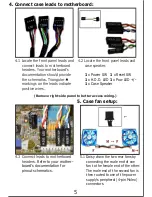


5.1 Daisy chain the two rear fans by
connecting the male end of one
fan to the female end of the other.
The male end of the second fan is
then routed to one of the power
supply’s peripheral (4-pin Molex)
connectors.
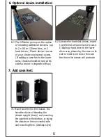
6.1 The X-Master gives you the option
of installing additional devices. (up
to 2 x 80 or 120mm fans, or 2
hard drives.) Mount device to area
of your choice and screw to case.
(If adding a case fan to the lower
area, chassis should be laid on its
side so as not to impede airflow.)
5. Case fan setup:
6
(Remove right-side panel to better access wiring.)
2. :
Install 3½” and 5¼” drives
4
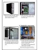
3.1 Remove the metal PCI slot cover(s)
from the slots to be used and install
devices into their respective slots.
(i.e. x1, x8, x16, etc.)
The X-Master can accommodate PCI
cards up to 9” in length.
3. Install PCI components:
3
2.4 Remove the front panel drive bay cover.
Remove the ‘drive-rail pins’ and remount
into notch #2. Mount rails to the sides to
the optical drive and install.
2.7 If installing a 3½” device that needs
to be accessible from the front panel,
you will need to place the device into
the preferred position, then screw to
case.
2.5 Remove the right-side panel. Extract
the two rear screws and slide the
panel outward to release.
2.6 Install hard-drive(s) into the side and
/or upper 3½” drive bay(s) and se-
cure to the case.
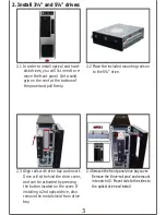
2.2 Place the included mounting rails on
to the
drive.
5¼”
2.1 In order to install optical and hard-
disk drives, you will 1st need to re-
move the front panel. Get a solid
grip on the vent at the bottom of
the panel and pull firmly.
2.3 Align rails with drive bay and insert.
Drive will sit behind the drive cover,
and can be activated by pressing
the button located on the cover. If
installing a 2nd optical drive, also
remove the metal shield from drive
bay.
2
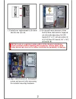
1.4 For standoff screw placement, follow
the M/B Holes Index which is engraved
onto the motherboard tray. Full ATX
boards (9.6” x 12”) will use notches A1-
A10. Full Micro ATX boards (9.6” x 9.6”)
will use B1-B9.
1.5 Align motherboard over the standoff
screws and secure to the case using
the included mounting hardware.
NOTE: Touch an unpainted metal section of the chassis to discharge
static electricity before handling PC components. An anti-static wrist
strap should also be worn to further minimize the possibility of damage.
1.3 Install your motherboard’s I/O shield
into the rear I/O slot.
1
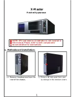
1. Motherboard installation:
1.1 Remove thumbscrews from the
rear of the chassis.
NOTE:
CPU and memory installation is not covered in
this manual. Please refer to each components’
documentation for instructions.
1.
Motherboard installation........................
3.
Install PCI components..........................
4.
Connect case leads to motherboard..........
6.
Optional device installation.....................
7.
Add case feet.....................................
8.
Complete the installation..................................
9.
USB/1394/Audio cable pin-assignments..............
5.
Case fan setup......................................
X-Master
Finished Appearance
1.2 Remove left-side panel from case
by sliding it in the direction shown.
CONTENTS
2.
Install 3½” and 5¼” drives......................
5
4.1 Locate the front panel leads and
connect leads to motherboard
headers. Your motherboard’s
documentation should provide
the schematics. Triangular
markings on the leads indicate
positive wires.
4. Connect case leads to motherboard:
4.3 Connect leads to motherboard
headers
. Refer to your mother-
board’s documentation for
pinout schematics.
4.2 Locate the front panel leads and
case speaker.
1
x Power SW
1
x Reset SW
1
x H.D.D. LED
1
x Pow LED +/-
1
x Case Speaker
*Please note the position of your PCI card’s external
power connector (if any). Some cards require extra
space in order to accommodate their power connectors.
6. Optional device installation:
6.2 Likewise for hard-disk drives, mount
to preferred area and screw to case.
If adding a hard drive to the lower
drive area, please lay the case on its
side or make sure to use the case
feet since the screws will protrude.
7. Add case feet:
7.1 Mount case feet to the chassis. You
have the choice of standing the
chassis upright (tower) and mounting
the case feet to the bottom, or laying
the chassis on the non-vented side
and mounting them. (desktop style)
7
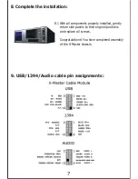
9. USB/1394/Audio cable pin assignments:
8. Complete the installation:
8.1 With all components properly installed, gently
return side panels to their original positions
and replace all screws.
Congratulations! You have completed assembly
of the X-Master chassis.
1
3
4
5
5
6
6
7
7


