
Extreme Power SPEC Pak
™
Receptacle
Assembly Instructions
Connector
“ X ”
“ X ”
Series
Amps
inches
m m
PP15/45
15-45
5/16
7.9
PP75
75
9/16
14.5
PP120
120
15/16
24
PP180
180
1-1/8
28.6
Hood Up
Hood Down
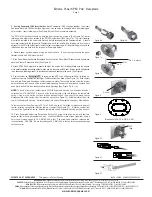
SPEC Pak Receptacle Kit Components
Powerpole
®
Holder Receptacle Shell Panel Mount Gasket Hardware Bag
Figure 1
Receptacle Side -
Hood Up
Plug Side -
Hood Down
www.andersonpower.com
1. Cable and / or Wire Preparation
a. Jacketed Cable – Strip approximately 4 inches (51 mm) of the outer jacket. Strip insulation from
individual wires per Table 1 (See Figure 1), being careful not to damage the copper conductors. See
Powerpole assembly instructions (1S1072) for more detail, if necessary.
b. Discrete Wire – Strip insulation from individual wires per Table 1 (See Figure 1), being careful not to
damage the copper conductors. See Powerpole assembly instructions (1S1072) for more detail if necessary.
Table 1
2. Terminate Powerpole contacts to individual wires by inserting contact into the recommended Anderson
crimping tool and crimp. For a full list of crimp tools see the connector Tooling section of the Extreme Data
Sheet or on the APP website. It is important to keep all contacts parallel to each other while
crimping. This will ensure that contacts remain in the proper position for mating and unmating
once installed into Powerpole Housings and will make installation into Powerpole Holder easier
(See Figure 2).
NOTE: Crimping with non-APP recommended tools may produce high resistance or contact distortion
resulting in improper seating of the contact in the Powerpole Housing. Use of other tools may also affect
UL & CSA approval.
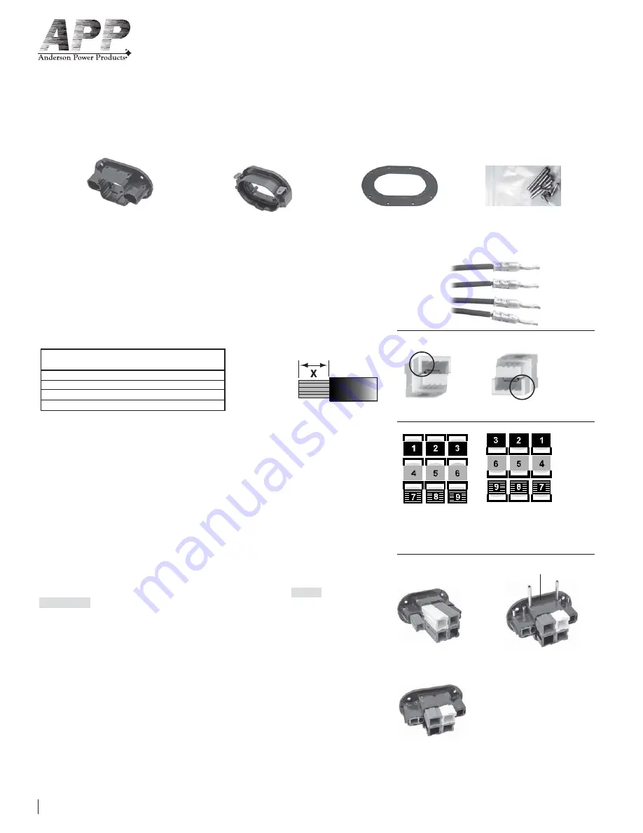
3. Block Powerpoles together where appropriate by interlocking dovetails on Powerpole housings.
Standard orientation for Powerpoles in the SPEC Pak Receptacles is Hood Up (See Figure 3a). Standard
orientation in the SPEC Pak Plugs is Hood Down (See Figure 3b). Individual Powerpoles maintain their
row within mating blocks of Powerpoles, but are reversed in their column order (See Figure 4).
4. The Powerpole Holder is labeled on the back of the holder flange with Plug
on one side and
Receptacle
on the opposite side. Position Powerpole Holder so that the receptacle is facing up. Insert
pre-blocked Powerpole Housings into Powerpole Holder from the rear (See Figure 5a). Powerpole block
should be oriented Hood Up for Receptacles and Hood Down for Plugs (See Figures 3a & 3b). Line up
holes in the Powerpole block with retaining pin holes in the Powerpole Holder.
Insert retaining pins into the
Holder until flush with edges (See Figure 5b). Retaining pins should be inserted into all holes in the holder.
For the PP120 4 position holder, DO NOT insert a retaining pin in the center hole (See Figure 5c).
NO CENTER PIN
with PP120 4
position
Figure 2
Figure 3a Figure 3b
Figure 4
Figure 5a Figure 5c
Figure 5b


