background image

READ AND SAVE THESE INSTRUCTIONS

 CAUTION

1.  Read all instructions before beginning installation.
2.  Improper installation may cause property damage or injury. Installation, service, and maintenance must be performed by a 

qualified service technician.

3.  Do not use in pool applications. Pool chemicals can damage the dehumidifier.
4.  Do not use solvents or cleaners on or near the circuit board. Chemicals can damage circuit board components.
5.  Wait 24 hours before running the unit if it was not shipped or stored in the upright position

 WARNING

1.  120 Volts may cause serious injury from electric shock. Disconnect electrical power before starting installation or servicing. 

Leave power disconnected until installation/service is completed.

2.  Sharp edges may cause serious injury from cuts. Use care when cutting plenum openings and handling duct work.
3.  Dropping may cause personal injury or equipment damage. Handle with care and follow installation instructions.

SAFETY INSTRUCTIONS

TABLE OF CONTENTS

Safety Instructions

 .  .  .  .  .  .  .  .  .  .  .  .  .  .  .  .  .  .  .  .  .  .  .  .  .  .  .  .  .  .  .  .  .  .  .  .  .  .  .  .1

Specifications

 .  .  .  .  .  .  .  .  .  .  .  .  .  .  .  .  .  .  .  .  .  .  .  .  .  .  .  .  .  .  .  .  .  .  .  .  .  .  .  .  .  .  .  .2

Set Up Dehumidifier for Installation

   .  .  .  .  .  .  .  .  .  .  .  .  .  .  .  .  .  .  .  .  .  .  .  .2 

  Packaging Content  .  .  .  .  .  .  .  .  .  .  .  .  .  .  .  .  .  .  .  .  .  .  .  .  .  .  .  .  .  .  .  .  .  .  .  .  .  .  .2 
  Duct Collars   .  .  .  .  .  .  .  .  .  .  .  .  .  .  .  .  .  .  .  .  .  .  .  .  .  .  .  .  .  .  .  .  .  .  .  .  .  .  .  .  .  .  .  .2

Location Considerations

 .  .  .  .  .  .  .  .  .  .  .  .  .  .  .  .  .  .  .  .  .  .  .  .  .  .  .  .  .  .  .  .  .  .  .3

Installation

 .  .  .  .  .  .  .  .  .  .  .  .  .  .  .  .  .  .  .  .  .  .  .  .  .  .  .  .  .  .  .  .  .  .  .  .  .  .  .  .  .  .  .  .  .  .  .3 

 Leveling   .  .  .  .  .  .  .  .  .  .  .  .  .  .  .  .  .  .  .  .  .  .  .  .  .  .  .  .  .  .  .  .  .  .  .  .  .  .  .  .  .  .  .  .  .  .  .3 
  Ductwork Installation .  .  .  .  .  .  .  .  .  .  .  .  .  .  .  .  .  .  .  .  .  .  .  .  .  .  .  .  .  .  .  .  .  .  .  .  .3 
  Drain Tubing and Condensate Pump Installation   .  .  .  .  .  .  .  .  .  .  .  .  .  .  .4

Model 76 – Crawl Space Control and Wiring

   .  .  .  .  .  .  .  .  .  .  .  .  .  .  .  .5

Air Cycling

 .  .  .  .  .  .  .  .  .  .  .  .  .  .  .  .  .  .  .  .  .  .  .  .  .  .  .  .  .  .  .  .  .  .  .  .  .  .  .  .  .  .  .  .  .  .  .5

System Set-Up, Check & Start-Up

   .  .  .  .  .  .  .  .  .  .  .  .  .  .  .  .  .  .  .  .  .  .  .  .  .  .6 

  Remote Control – Crawl Space .  .  .  .  .  .  .  .  .  .  .  .  .  .  .  .  .  .  .  .  .  .  .  .  .  .  .  .  .6 
  Ventilation / Air Cycling .  .  .  .  .  .  .  .  .  .  .  .  .  .  .  .  .  .  .  .  .  .  .  .  .  .  .  .  .  .  .  .  .  .  .7 
  System Check .  .  .  .  .  .  .  .  .  .  .  .  .  .  .  .  .  .  .  .  .  .  .  .  .  .  .  .  .  .  .  .  .  .  .  .  .  .  .  .  .  .  .7 
  Crawl Space Using the Dehumidifier Control .  .  .  .  .  .  .  .  .  .  .  .  .  .  .  .  .  .8 
  Crawl Space Remote Control Using Model 76  .  .  .  .  .  .  .  .  .  .  .  .  .  .  .  .  .8 
 Start-Up   .  .  .  .  .  .  .  .  .  .  .  .  .  .  .  .  .  .  .  .  .  .  .  .  .  .  .  .  .  .  .  .  .  .  .  .  .  .  .  .  .  .  .  .  .  .  .8

Troubleshooting

   .  .  .  .  .  .  .  .  .  .  .  .  .  .  .  .  .  .  .  .  .  .  .  .  .  .  .  .  .  .  .  .  .  .  .  .  .  .  .  .  .  .9 

  Table 1 – Diagnostic Codes .  .  .  .  .  .  .  .  .  .  .  .  .  .  .  .  .  .  .  .  .  .  .  .  .  .  .  .  .  .  .  .9 
  Table 2 – Troubleshooting Guide .  .  .  .  .  .  .  .  .  .  .  .  .  .  .  .  .  .  .  .  .  .  .  .  .  .  .10

Service Parts

 .  .  .  .  .  .  .  .  .  .  .  .  .  .  .  .  .  .  .  .  .  .  .  .  .  .  .  .  .  .  .  .  .  .  .  .  .  .  .  .  .  .  .  .11

Model 1820 Dehumidifier

Installation Instructions

1

Summary of Contents for 1820

Page 1: ... is completed 2 Sharp edges may cause serious injury from cuts Use care when cutting plenum openings and handling duct work 3 Dropping may cause personal injury or equipment damage Handle with care and follow installation instructions SAFETY INSTRUCTIONS TABLE OF CONTENTS Safety Instructions 1 Specifications 2 Set Up Dehumidifier for Installation 2 Packaging Content 2 Duct Collars 2 Location Consi...

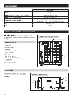
Page 2: ...current Dehumidifier Inlet Air Conditions Dehumidification 50 F 104 F 40 F dew point minimum Ventilation 40 F 140 F 0 RH 99 RH non condensing Filter MERV 8 washable Airflow 200 CFM 1 Dehumidifier 2 Inlet Outlet Collars 3 Literature a Installation Instructions b Owner s Manual 4 Parts Bag a 10 x 1 2 Screws 9 b Threaded Barbed Fitting for Drain Connections c Torx Bit 5 10 foot 3 4 Drain Tube PACKAGI...

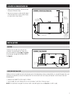
Page 3: ...quired to accommodate drain fittings and a secondary condensate pan Leveling is required to ensure proper drainage from the dehumidifier See Figure 4 Adding 5 10 feet of insulated ductwork to the inlet and outlet of the dehumidifier will ensure dehumidified air is circulated throughout the crawl space and will reduce the noise level of the dehumidifier Point the inlet and outlet ducts in opposite ...

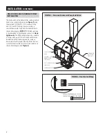
Page 4: ...ction Hand tighten only The 4856 condensate pump is capable of lifting water up to 22 feet The dehumidifier can be elevated while remaining level to increase downward slope for proper draining Wire the float switch terminals to the normally closed contacts on the condensate pump see Figure 6 8 DIAMETER INSULATED FLEX DUCT 3 4 CLEAR PVC TUBING INCLUDED CONDENSATE PUMP FLOAT SWITCH WIRE 3 4 MNPT x 3...

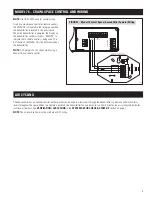
Page 5: ...s not an option when using a Model 76 as a remote control A B ODT Sensor Remote Gh Rf Cf Gs Y W HVAC EQUIP DH DH R C B A MODEL 76 CONTROL FIGURE 7 Model 76 Crawl Space Sealed Attic Remote Wiring 90 1860 AIR CYCLING The dehumidifier has an optional ventilation feature that can be used to circulate air through the dehumidifier to promote uniform humidity levels throughout the space When this feature...

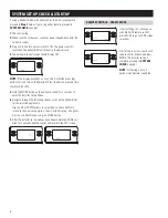
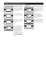
Page 6: ...n the on board control for 3 seconds to enter the Installer Set up Menu 6 Navigate through the following screens to set up the dehumidifier for the installed application Use the UP or DOWN arrows to select items and use MODE to switch to the next set up option To exit installer set up all options must be scrolled through using the MODE button 7 After the installer set up options have been complete...

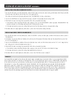
Page 7: ...TEM SET UP CHECK START UP CONTINUED VENTILATION AIR CYCLING 90 1854 If not using the dehumidifier to periodically cycle air in the crawl space press MODE to go to ZONE screen selections 90 1854 If using the dehumidifier for air cycling Enable and press MODE 90 1854 Press MODE at the VENT TIMED screen to go to ventilation time selection screen 90 1854 Press the UP or DOWN arrows to adjust the venti...

Page 8: ...ng will be replaced by the measured humidity and AIR SAMPLING will show on the display 2 Use the UP or DOWN button to adjust the humidity setting as desired The recommended initial setting is 59 3 After three 3 minutes of sampling the measured humidity will be compared to the setting a If the humidity is above the setting the dehumidifier compressor turns on and AIR SAMPLING will be replaced by DE...

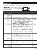
Page 9: ...ed to the refrigeration line proceed to the next step 4 Reset the fault by cycling power to the dehumidifier 5 Turn the humidity setting down below room home humidity level to make a dehumidification call 6 Allow the fan and compressor to run for approximately 10 15 minutes and then enter diagnostic test mode by simultaneously pressing the UP ARROW and MODE buttons for 3 seconds The LCD will displ...

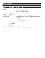
Page 10: ...at control board and empty condensate pan If no float switch installed check that the jumper is installed at the float switch terminals on the control board Coil frosting Lack of or reduced airflow Check dehumidifier air filter and wash or replace Check for blocked duct work Inlet air conditions below 60 F Increase the humidity setting Inlet air temperature is outside of the 50 F 104 F range or th...

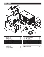
Page 11: ...eh 5699 8 Fan with 6MFD Capacitor 5694 9 Wire Harness Power Deh 5454 10 Sensor Low Temperature Deh 5455 No Part Description Part No 11 Sensor High Temperature Deh 5456 12 Leveling Foot Deh 5457 13 Capacitor 45MFD 370VAC 5458 14 Capacitor 6MFD 250VAC 5582 15 RH Sensor Deh 5460 16 Drain Tube Fitting 5665 17 Compressor Overload Switch 5697 Not Shown Condensate Pump with Tubing 4856 SERVICE PARTS 1 4 ...

Page 12: ...AprilairePartners com P O Box 1467 Madison WI 53701 1467 800 334 6011 F 608 257 4357 Printed in USA 2017 Aprilaire Division of Research Products Corporation 10012343 B2207621B 9 17 ...

Reviews: