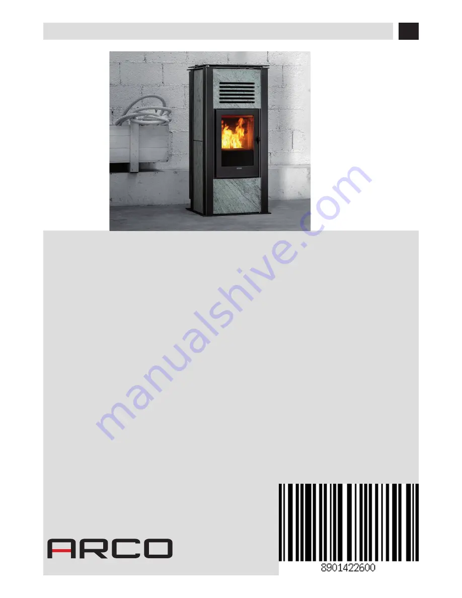
background image

INSTALLATION GUIDE

EN

PELLET STOVE

ASKO PC10

comfort air

Instructions in English

Summary of Contents for ASKO PC10

Page 1: ...INSTALLATION GUIDE EN PELLET STOVE ASKO PC10 comfort air Instructions in English ...

Page 2: ...OP DISASSEMBLY 37 7 REMOVING THE BACK FOR MAINTENANCE 38 8 CONNECTIONS TO ADDITIONAL DEVICES 39 9 ELECTRICAL CONNECTION 41 10 ANTENNA ASSEMBLY 42 11 LOADING THE PELLETS 43 12 FIRST START UP 44 13 REMOTE CONTROL MAX 46 14 EMERGENCY PANEL 53 15 SAFETY DEVICES 54 16 ALARMS 56 17 RECOMMENDATIONS FOR SAFE USE 59 18 CLEANING 60 19 FAULTS CAUSES SOLUTIONS 66 20 AIR COMFORT STOVE CIRCUIT BOARD 69 ...

Page 3: ... for the system installed By system one means Stove Chimney Air inlet REVISIONSTOTHE PUBLICATION The content of this manual is strictly technical and the property of MCZ Group Spa No part of this manual may be translated into other languages adapted or reproduced even in part in other mechanical or electronic forms photocopies recordings or other without the prior written authorisation from MCZ Gr...

Page 4: ...e hopper The instructions provided in this manual must always be complied with to ensure the product and any electronic appliances connected to it are used correctly and accidents are prevented This appliance can be used by children aged 8 years and above and persons with reduced physical sensory or mental capabilities or lack of experience and knowledge if they have been given supervision or inst...

Page 5: ...oduct with the door open or the glass broken The doors covers on the appliance must remain closed when it is not used The product must be powered by an electrical system that is equipped with an effective earthing device Switch the product off in the event of a fault or malfunction Accumulated unburned pellets in the burner after each failed start up must beremovedbeforelightingagain Checkthattheb...

Page 6: ...the surface on which the weight of the product willrestandprovidesuitableinsulationifitismadeofflammablematerial e g wood fitted carpet or plastic Live electrical parts only power the product once it has been fully assembled Disconnect the product from the 230V power supply before performing any maintenance operation Improperuseorpoormaintenanceoftheproductcancausehazardoussituations to arise It i...

Page 7: ...e attested by a document to serve as proof of purchase invoice and or receipt that shows the name of the vendor and the date on which the purchase was made forwarding of the completed certificate of guarantee within 8 days of purchase Furthermore the product must be installed and started by specialised personnel who must where provided issue a declaration of conformity of the plant and of the prop...

Page 8: ... maintenance performed by an authorised technician or qualified personnel will result in the loss of the warranty Also excluded from this guarantee are parts subject to normal wear such as gaskets glass claddings and cast iron grids painted chrome plated or gilded parts handles and electric cables bulbs indicator lights knobs all parts which can be removed from the hearth Variations in colour of t...

Page 9: ...out authorisation Allpartsmustbereplacedwithoriginalspareparts WARNINGS FORTHE CORRECT DISPOSAL OFTHE PRODUCT The owner is the sole party responsible for demolishing and disposing of the product This must be performed in compliance with laws related to safety and environmental protection in force in his her country At the end of its working life the product must not be disposed of as urban waste I...

Page 10: ...o ensure good combustion the pellets must be stored in a dry place and protected from dirt Pellets are usually supplied in 15 kg bags therefore storing them is very convenient Good quality pellets guarantee good combustion thereby decreasing harmful emissions into the atmosphere The poorer the quality of the fuel the more often the internal parts of the brazier and combustion chamber must becleane...

Page 11: ...nd the integrity of the home The installation of the appliance must ensure easy access to clean the appliance itself the smoke outlet pipes and the flue It is forbidden to install the stove in rooms with a fire hazard Installation in studio flats bedrooms and bathrooms is only allowed with sealed or closed appliances equipped with suitable combustion air ducting directly outside Always maintain ad...

Page 12: ... in force SMOKE FLUE The flue or chimney is of great importance for the proper operation of a solid fuel burning heating appliance with natural draught as modern heating appliances have high efficiency with cooler flue gasses and consequently less draught it is therefore essential that the flue is built up to standard and always kept in perfect working order A flue that serves a pellet wood fuelle...

Page 13: ...nd reduce smoke cooling It should be separated from combustible or flammable materials with an air gap or insulating materials check the distance specified by the manufacturer of the fireplace according to EN1443 The chimney opening must be in the same room as the appliance oratmostintheadjoiningroom andhaveasootandcondensationcollectionchamberbeneaththeopening andbeaccessible via a sealed metal h...

Page 14: ...imensioned in accordance with the general method of calculation of UNI EN13384 1 or other proven efficiency methods Below is a list of some flues available on the market Steel chimney AISI 316 with double chamber insulated with ceramic fibre or equivalent resistant up to 400 C Refractory chimney with double insulated chamber and external lightweight concrete cladding with cellular material such as...

Page 15: ...fety of the system CHIMNEY The chimney is a crucial element for the heating appliance to work properly we recommend a wind proof chimney A see Figure 7 The area of the opening for smoke extraction must be at least double the cross section of the smoke duct flue system and arranged so thatsmokeextractionisensuredeven in strong wind The chimney must prevent rain snow or animals from entering the chi...

Page 16: ...cause a depression in the room Make sure that with all appliances on the pressure drop between the room and the outside does not exceed the value of 4 Pa also for Oyster appliances if the combustion air has not been suitably ducted outside If necessary increase the intake section of the air inlet which must be made at floor level and always protected with a bird proof outer protection grid and in ...

Page 17: ...ength with 1 accessible 90 bend 6 5 metres Maximum length with 3 accessible 90 bends 4 5 metres Maximum number of accessible 90 bends 3 Horizontal sections minimum incline 3 4 metres Use smoke ducts with a diameter of 80mm or 100mm depending on the type of system with silicone gaskets or similar gaskets that can withstand the high operating temperatures of the appliance min T200 class P1 The use o...

Page 18: ...lar the minimum safety distances from combustible materials The previous rules also apply for holes made in walls 2 Oldflue minimumpipeØ100mmwiththeinclusionof an external access door for chimney cleaning 3 External flue made of insulated stainless steel pipes i e with double walls minimum Ø100mm all securely mounted on the wall With wind proof chimney See fig 7 type A 4 DuctingsystemusingTjointst...

Page 19: ... 266 151 279 280 384 149 Ø50 Ø50 Ø80 550 532 1196 20 17 3 DRAWINGS ANDTECHNICAL FEATURES Technical Dept All rights reserved Reproduction is prohibited DRAWINGS AND CHARACTERISTICS DIMENSIONS OF ASKO PC10 COMFORT AIR STOVE ...

Page 20: ...let hourly consumption Min 0 7 kg h Max 2 2 kg h Autonomy At min 39 h At max 12 h Heatable volume m3 217 40 248 35 290 30 Combustion air inlet Ø 50 mm Smoke outlet Ø 80 mm Air intlet 80 cm2 Rated electrical power EN 60335 1 130W Max 370W Supply voltage and frequency 230Volt 50 Hz Net weight 240 kg with cladding Weight with packaging 260 kg with cladding Distance from combustible material back side...

Page 21: ...n the packaging over and handle the majolica parts with care The stoves are delivered with two packages one for the structure and one with the stone cladding Open the package remove the cardboard polystyrene and any straps and position the stove in the preset place making sure that it complies with the requirements The stove body or unit must always be kept in a vertical position when handled and ...

Page 22: ...s 20 4 UNPACKING To remove the stove remove the two screws and plate s from the stove s foot There are four brackets s REMOVING THE FASTENING BRACKETS ...

Page 23: ... the connecting pipe If the stove needs to be connected to an outlet pipe which goes through the rear wall to connect to the flue take utmost care to make sure that the joint is not forced If the stove smoke outlet is forced or used improperly to lift it or position it the operation of the stove can be damagedirreparably 1 TURN THE FEET CLOCKWISE TO LOWER THE STOVE 2 TURN THE FEET COUNTERCLOCKWISE...

Page 24: ...have codes on the inside required for correct positioning see image below Take the package with the stone panels picture below prepare them for assembly and follow the instructions on the following pages The stones are delicate therefore handle with care POS DESCRIPTION No LD1 RH SIDE PANEL 1 1 LD2 RH SIDE PANEL 2 1 LS1 LH SIDE PANEL 1 1 LS2 LH SIDE PANEL 2 1 S2 LOWER STONE PANEL 1 S3 UPPER STONE ...

Page 25: ...L To insert panel S2 proceed as follows first insert the panel in the lower section of the stove place the panel S2 close to the stove so that the upper stove rabbet enters the panel Attention Should any difficulties be encountered in inserting the S2 stone panel the upper bracket k may be removedtomakeinsertioneasier ...

Page 26: ... j 24 5 CLADDING ASSEMBLY To remove bracket k open the firebox door and remove the two screws j After inserting stone S2 in the lower part place panel S2 next to the stove and fit bracket k locking panel S2 back on ...

Page 27: ...served Reproduction is prohibited INSTALLINGTHE FRONT UPPER PANEL To install the front upper panel S3 proceed as follows Tilt panel S3 so it enters the upper rabbet place panel S3 next to the stove structure Insert the lower rabbet of panel S3 onto the stove structure ...

Page 28: ...rspacefacingup seepicturebelow Thepanelisnotreversible The nuts under the filling door are not closed for easier insertion of panel S3 Therefore after positioning panel S3 lift the door and tighten the two nuts under the top spacers well in order to lock the panel once and for all ...

Page 29: ...ed INSTALLINGTHE SIDE PANELS To fit the side panels first remove back profiles A as follows lift the pellet filling door V remove the two screws y one for the right hand profile and one for the left hand one remove the two screws x two for the right hand profile and two for the left hand one ...

Page 30: ...A 28 5 CLADDING ASSEMBLY At this stage remove profile A and place it in a safe position until it is used again ...

Page 31: ... 5 CLADDING ASSEMBLY Technical Dept All rights reserved Reproduction is prohibited Before inserting the stone panels also remove the two plates B by removing the two screws x required for locking the side panels ...

Page 32: ...fore proceeding with fitting the stone panels it is recommended to check on the floor to ensure the colour grain ofthepanelstobefittedontothesidesofthestovematch Take stone panel LD1 and insert it in the guide at the bottom of the structure ...

Page 33: ...LD1 x B 31 5 CLADDING ASSEMBLY Technical Dept All rights reserved Reproduction is prohibited Take one bracket B previously removed and fit it back in with the two screws x ...

Page 34: ...LD1 LD1 P P 32 5 CLADDING ASSEMBLY Take separator P supplied with the stove one for the right side and one for the left side and insert it in the rabbet of panel S1 ...

Page 35: ...LD2 LD1 LD1 P 33 5 CLADDING ASSEMBLY Technical Dept All rights reserved Reproduction is prohibited Take panel LD2 and insert it in the guide of separator P which you have just fitted on the lower panel LD1 ...

Page 36: ...B LD2 x 34 5 CLADDING ASSEMBLY At this stage take the other bracket B and fit it back in its seat securing it with the two screws x ...

Page 37: ...A 35 5 CLADDING ASSEMBLY Technical Dept All rights reserved Reproduction is prohibited Take profile A you have previously taken down and fit it back onto the structure ...

Page 38: ...SEMBLY At the rear fasten profile A with the two screws x while at the top lift the tank door and fasten the two screws y Fit the panels on the left side in the same way paying attention to use panels marked with LS1 and LS2 ...

Page 39: ...eserved Reproduction is prohibited DISASSEMBLINGTHETOP In case of need it is possible to remove the upper cover U from its seat simply by lifting it whereas to remove the profile underneath R it is required to unscrew the two pins T the two screws w and lift it ...

Page 40: ...must be performed on a component of the stove the rear panel can be removed if the distances from the walls allow it otherwise the maintenance can be performed by removing the side of the stove To remove the rear panel remove the 8 rear screws a and pull the panel L away ...

Page 41: ...eb Wi Fi Interface N using the holes on the back of the product and follow the instructions on the product chosen USB SOCKET ThereisaUSBsocketonthebackofthestove ifasoftwareupdateisrequired theceramic metalpartsdonothavetoberemovedtoreach the socket directly in the circuit board pos 5 in the PCB Attention TheUSBsocket mustbeusedbyskilledtechnicians Riskofdamagingtheproduct ...

Page 42: ... Air stoves can channel the air into other rooms through the two rear vents see image below Remove the vents as follows remove the two screws V extract vent B remove grid G channel the air If you do not wish to channel the air the hot air may be let out through the rear via these vents ...

Page 43: ...anyotherpartofthestove STOVE POWER SUPPLY After connecting the power cable to the back of the stove turn the switch to I or ON The stove is then powered Thereisafuseboxalsointheswitchblocknexttothepowersocket Openthiscompartmentbysimplyliftingthecover usingascrewdriver as a lever from inside the power outlet compartment Inside there are two fuses 3 15 A delayed which may need to be replaced if the...

Page 44: ...ANTENNA Take the antenna A from the bag containing the instructions Screw the antenna A clockwise on screw V near the control panel until the mobile part is positioned upwards Attention Tightentheantennacompletelywithoutforcingittopreventreceptiondamage ...

Page 45: ...n that comes with the stoveitself Whenloading donotletthepelletbagcomeintocontactwithhotsurfaces Neverremovetheprotectiongridinsidethehopper No other type of fuel other than pellets is to be inserted into the hopper in compliance with above mentioned specifications Storethesparefuelatanadequatesafedistance Donotpourpelletsdirectlyontothebrazierbutonlyintothehopper Whentheapplianceisrunningandwheni...

Page 46: ...ct can be operated in safe mode via the rear emergency panel In this configuration the stove can only operate in manual mode and with the possibility to choose between 3 power levels SWITCHINGTHE STOVE ONWITHOUTTHE REMOTE CONTROL To switch the stove on move selector D to the ON position The RED LED goes off upon start up while the GREEN LED starts to flash until the start up stage is complete Once...

Page 47: ...lose to the stove and as mentioned air the room The smoke and smell of paint will disappear after about an hour of operation however they are not harmful in any case The boiler will be subject to expansion and contraction during the lighting and cooling down stages and may therefore make slight creaking noises This is absolutely normal as the structure is made of laminated steel and must not be co...

Page 48: ...When the remote control is powered it automatically prompts to set the time The remote control has a special icon on the display to indicate when the batteries are almost flat If the flat battery icon appears the batteries are almost flat and the remote control is about to switch off Used batteries contain metals which are harmful to the environment so they must be disposed of separately in approp...

Page 49: ...r 24h and finally the day will start to flash Confirm this data to exit the settings NOTE each time the remote control is powered the time is reset and the display automatically enters the time setting mode C F setting Only with the stove switched off by pressing key B for 5 one changes the unit of measure of the temperature from Celsius to Fahrenheit and vice versa SETTINGTHE OPERATING MODE With ...

Page 50: ...lame is automatically set to a minimum when the set temperature value is reached if the bars are all full the stove is on flame power 5 if only one bar is full the stove is on flame power 1 If the ventilation is MANUALLY set the function which limits the maximum power of the stove according to the ventilation is enabled COMFORT AIR 2 FANS maximum power level total of the levels of ventilation Even...

Page 51: ... product switches off and remains on stand by until the room temperature drops 2 degrees below the desired temperature and in any case for at least 5 minutes from the last shutdown The product is then switched on again Figure 4 Iftheroomisnotsufficientlyinsulated flamemodulationdoesnotallowthesettemperaturetostaysatisfiedfor20consecutiveminutes and the product will not switch off NOTE It is recomm...

Page 52: ...emains set on 3 for silent operation as it is in automatic mode The speed of each fan identified with 1 or 2 above the level bars in products with 2 fans comfort air models can be scrolled and set via key D NOTE In the event a replacement remote control is purchased if you need to change the default setting proceed as follows with the remote control switched on press buttons D E at the same time f...

Page 53: ...the dashes appear and confirm NO AIR FUNCTION SF The NO AIR function allows the stove to operate at the minimum power throughout the night with no room ventilation This function is only available in AUTO and MAN mode not in TIMER mode Proceed as follows to set it from the VENTILATION setting by pressing key D press key D again and you will access theSLEEP setting mode From when the dashes are disp...

Page 54: ...time slot editing mode saving all variations confirmed with key E up to that time and one goes back to the time slot display condition While by pressing key A or leaving the keypad idle for 30 one goes directly to the basic display saving all variations confirmed with key E up to that time Activating theTIMER ECO time slots In ECO mode one can activate up to 6 time slots customising switch on and ...

Page 55: ...ree position selector for the following functions OFF Stove switched off manually without remote control REMOTE Stovecontrolledexclusivelyfromtheremote control ON Stove switched on manually without the remote control E Three position selector to select the power MIN Selector to make the stove work at MINIMUM power without the remote control and with selector 4 on ON MED Selector to make the stove ...

Page 56: ... fan stops the circuit board promptly blocks the supply of pellets and the alarm is displayed GEAR MOTOR BREAKAGE If the gear motor stops the product switches off and the relative alarm is signalled TEMPORARY POWER CUT If a power cut occurs during operation the product automatically sets itself in cooling mode when the power is restored and then it restarts FAILED START UP If no flame lights durin...

Page 57: ... being empty Enable the function as follows Set the first selector to OFF Set the second selector to MED Make sure that OFF appears on the display because this function can only be activated with the stove completely cold off and the selector set to OFF Press the TEST key 3 times consecutively within 2 seconds FEED SCREW will appear on the display in two subsequent intervals Press the TEST key onc...

Page 58: ...e pellet hopper exceeds the required safety threshold The structure overheats due to reduced heat dissipation The structure is too hot because the product has been used for too long at the maximum power or there is poor ventilation When the product is sufficiently cold press button B on the control panel or OFF on the remote control to cancel alarm A03 Once the alarm is cancelled the product can b...

Page 59: ...replaced SER Routine maintenance warning after 2000 hours of operation When this flashing message appears upon start up it indicates that the preset operating hours before maintenance is due have elapsed and that an MCZ qualified technician must be contacted for maintenance Exiting the alarm conditions Follow the procedure described below to restore normal stove operation after an alarm has been t...

Page 60: ...ion When the product is sufficiently cold press button B on the control panel or OFF on the remote control to cancel alarm A03 Once the alarm is cancelled the product can be switched on normally If A04 appears The stove switches off automatically Let the stove cool down for a few minutes and then switch it on again Check the smoke expulsion and verify the type of pellet used according to the instr...

Page 61: ... to guarantee that the product is installed in compliance with standards in force Furthermore it is of the utmost importance to respect the following simple rules Every time the brazier is removed for cleaning it must always be put back properly in the work position before using the product completely removing any residual filth left on the support base Pellets must never be loaded in the brazier ...

Page 62: ...quality pellets DAILY ORWEEKLY CLEANING PERFORMED BYTHE USER Brazier cleaning Before ignition always clean the T brazier and remove any ash or incrustation from it that might obstruct the air flow holes paying attention to hot ash In the case of ignition failure or if fuel in the tank runs out unburned pellets may accumulate in the brazier Always empty the residue in the brazier before each start ...

Page 63: ...ic glass with a dry brush or if it is very dirty spray a little specific detergent and clean with a cloth ATTENTION Do not use abrasive products and do not spray the glass cleaning product on the painted parts and on the door gaskets ceramicfibrecord CLEANINGTHE AIR FILTER A wire mesh air filter is found at the back of the stove whose purpose is to prevent dirt entering the motor body and the inte...

Page 64: ...isedandskilledtechniciansothateven thesealscanbereplaced CLEANINGTHE EXCHANGER Open the stove door remove the brazier and the ash pan Then remove the inside of the firebox starting from the two side pieces M and N Extract these parts by lifting them slightly upward and pulling them towards you Then remove the back L following the same procedure Attention Once the back L is removed part P which is ...

Page 65: ... the first ceramic C on the right and left side of the stove see the specific pages in this manual to remove the ceramics Then remove the two screws r the seal S and the plate T and clean the lateral walls of the firebox with a rigid rod or a bottle brush so that the dirt falls on the lower compartment CAUTION Ifnecessary replacetheseals Airstovesdonotrequirethiscleaning ...

Page 66: ...rizontalsectionsofthesmokeduct For information on periodically cleaning the flue contact a skilled chimney sweep Check the seal of the ceramic fibre gaskets on the door of the stove If necessary order new replacement seals from the retailer or contact an authorized service centre to carry out this task CAUTION The frequency with which the smoke outlet system is cleaned depends on the use of the bo...

Page 67: ...on the side of the product near the power socket Open the fusebox cover with a screwdriver and replace the fuses if necessary 3 15 A delayed seek assistance from an authorised and qualified technician CHECKINGTHE INTERNAL COMPONENTS ATTENTION Theinternalelectromechanicalcomponentsmustonlybecheckedbyqualifiedpersonnelwhosetechnicalexpertise includescombustionandelectricity Werecommendthatanannualma...

Page 68: ...lets are not fed See the previous anomaly The pellet temperature safety probe has been triggered Let the product cool down restore the thermostat until the lockout is off and switch the appliance back on If the problem persists contact Technical Assistance Chrono active Check if the chrono setting is active The door is not closed properly or the gaskets are worn Close the door and replace the gask...

Page 69: ...oles are clear Perform a general cleaning of the combustion chamber and the smoke duct Check the condition of the door gaskets Damp or unsuitable pellets Change the type of pellets Faulty smoke evacuation motor Check the motor and replace it if necessary The smoke evacuation motor does not work No electrical supply to the stove Check the mains voltage and the protection fuse The motor is faulty Ch...

Page 70: ...beandreplaceitifnecessary Faulty or malfunctioning control panel Check the panel and replace if necessary The product does not switch on No power supply Check that the plug is inserted and the main switch is in the I position Fuse tripped due to a fault Replace the fuse with one of the same characteristics 5x20 mmT 3 15A Check the brazier Clean the brazier and remove any deposits or residues of no...

Page 71: ... 2 GEAR MOTOR ENCODER 3 PRESSURETRANSDUCER 4 SMOKETEMPERATURE PROBE 5 SOFTWARE UPDATE USB 6 MODBUS COMMUNICATION FOR MODEM WI FI ETC 7 EMERGENCY PANEL 8 HOPPER OVERLOAD CUT OUT 9 AIR FAN 1 10 GEAR MOTOR 11 SMOKE FAN 12 SPARK PLUG 13 SWITCH 14 AIR FAN 2 PLEASE NOTEThe electrical wiring of individual components is fitted with pre wired connectors of different sizes LIVE ELECTRICAL CABLES DISCONNECT ...

Page 72: ...25 11 15 REV 2 8901422600 MCZ GROUP S p A Via La Croce n 8 33074Vigonovo di Fontanafredda PN ITALY Telephone 39 0434 599599 r a Fax 39 0434 599598 Internet www mcz it e mail mcz mcz it ...

Reviews: