background image

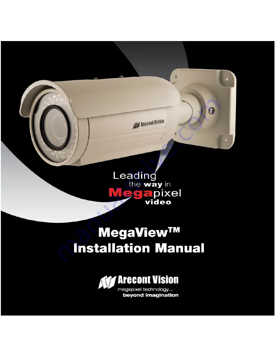
Arecont Vision MegaView

TM

 Installation Manual 

0 | P a g e


Summary of Contents for MegaView

Page 1: ...Arecont Vision MegaViewTM Installation Manual 0 P a g e ...

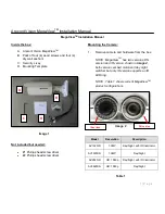
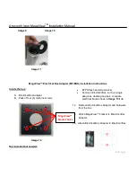
Page 2: ...r Mounting the Camera 1 Remove camera and hardware from the box NOTE MegaView TM has two versions DN version and IR version shown in image 2 both versions embed motorized day night switcher but only IR version supports an IR LED ring NOTE Table 1 shows current MegaView TM product configurations Image 2 Model Resolution Description AV1325IR 1 3MP Day Night with IR Illuminator AV1325DN 1 3MP Day Nig...

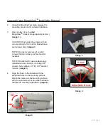
Page 3: ...camera body Image 4 NOTE Bracket screws are all security screws that are tamper proof and vandal resistant NOTE Bracket with 3 axes enables easy installation in any location including 360 camera body rotation 90 tilt 360 bracket rotation image 5 4 Align the holes in the camera with the prepared holes on the mounting surface Attach the camera to the mounting surface with the wood screws or any othe...

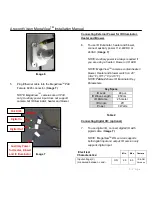
Page 4: ...re using a heater blower or IR LED NOTE MegaView TM cameras contain heater blower Heater and blower switch on 4C 39 2 F Off 7 C 44 6 F NOTE Table 2 shows IR Illuminator Key Parameters Key Specs IR Leds 48 pcs IR Wave Length 850nm IR Distance 25 meter IR Angle 45 Power 3 Watts Table 2 Connecting Digital I O optional 7 To use digital I O connect digital I O with pigtail cable Image 7 NOTE MegaView T...

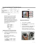
Page 5: ...comply with the requirements of the debouncing circuit Yellow OUT Red OUT Green IN Black IN Table 2 Adjusting the Focus Iris and Field of View 8 To adjust focus iris and field of view use security L key to adjust external lens screws shown in Image 8 NOTE The focus length range of MegaView TM is 4 5mm 10mm FOV as following Table 3 H FOV 4 5mm 10mm AV1325IR DN 48 22 AV2825IR DN 73 34 Table 3 Image ...

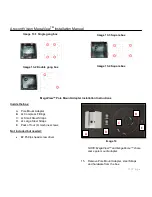
Page 6: ... Pack of four 4 machine screws Image 12 Not included but needed 2 Phillips head screw driver Common Electrical Box such as single gang box double gang box or square electrical boxes shown in Image 13 1 4 12 Remove Electrical Box Adapter and hardware from the box 13 Attach MegaView bracket to Electrical Box Adapter 14 Attach Electrical Box Adapter to Electrical Box MegaView Bracket holes ...

Page 7: ...unt Adapter Installation Instructions Inside the box A Pole Mount Adapter B 2x Compress Fittings C 2x Small Steel Straps D 2x Large Steel Straps E Pack of four 4 machine screws Not included but needed 2 Phillips head screw driver Image 14 NOTE MegaView and MegaDome share same pole mount adapter 15 Remove Pole Mount Adapter steel Straps and hardware from the box A B C D E ...

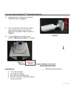
Page 8: ...the compression screws as shown in Image 16 18 To adjust MegaView bracket please reference Mounting the Camera if needed Image 15 Image 16 MegaView Corner Mount Adapter Installation Instructions Inside the box A Corner Mount Adapter B 2x Compression Fittings C Pack of four 4 machine screws D 2x Packs of four 4 wood screws and four 4 dry wall anchors Not included but needed 2 Phillips head screw dr...

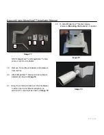
Page 9: ...unt Adapter and hardware from the box 20 Attach MegaView bracket to Corner Mount Adapter as shown in Image 18 21 Using the screws provided or other hardware to attach the Corner Mount Adapter to an exterior 90 corner wall as shown in Image 19 22 To adjust MegaView bracket please reference Mounting the Camera if needed Image 18 Image 19 A B C D ...

Page 10: ...Arecont Vision MegaViewTM Installation Manual 9 P a g e ...

Reviews: