background image


ARNAV Systems, Inc. 

16923 Meridian East 

P.O. Box 73730 

Puyallup, Washington 98375 

(253) 848-6060 


RCOM-100 

Installation GUIDE 


PART NUMBER 570-8050B 


27 November 2002 


Proprietary Notice 

The Information contained in this document is proprietary to ARNAV Systems, 
Inc., and shall not be reproduced or disclosed in whole or in part to persons not 
authorized by ARNAV. 


Summary of Contents for RCOM-100

Page 1: ...75 253 848 6060 RCOM 100 Installation GUIDE PART NUMBER 570 8050B 27 November 2002 Proprietary Notice The Information contained in this document is proprietary to ARNAV Systems Inc and shall not be reproduced or disclosed in whole or in part to persons not authorized by ARNAV ...

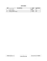
Page 2: ...ARNAV Systems Inc 1 Document No 570 8050B 27 November 2002 REVISIONS REV DESCRIPTION DATE APPROVAL Initial Release August 2002 LAJ A Minor Changes 11 15 02 LAJ B Added Antenna Doubler 11 27 02 LAJ ...

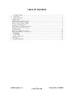
Page 3: ... Locations 4 Table 3 1 Transmit Cable Lengths 5 Table 3 2 Receive Cable Lengths 5 Securing The Mounting Tray 6 Transmit Receive Antenna Installation 7 Mounting the NAT PTA 12 Dialer 9 VC28 Mounting 10 Route Coax Cables for Tx and Rx 10 Wiring the RCOM 100 VC28 PTA 12 11 Description 12 4 DATA PORT 13 Asynchronous Services 13 Packet Services 13 5 SYSTEM TESTING 14 ...

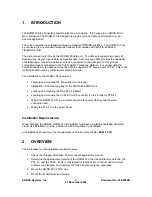
Page 4: ...uters for dial up services The installation to the RCOM 100 consists of Locating and mounting the transmit receive antenna Installation of the mounting tray for the ARINC 600 2MCU box Locating and mounting the NAT PTA 12 Dialer Locating and mounting the VC28 DC to DC converter 14 to 28 volts for PTA 12_ Wiring the RCOM 100 37 pin circular connector for power tip ring and the data connection port W...

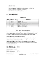
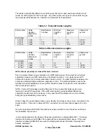
Page 5: ...stance between the equipment mounting location and the transmit receive antenna location The second restrictions is the distance allowed between the transmit antenna and any GPS antenna located on the aircraft The data below will help identify proper equipment and antenna locations Transmit Receive antenna and equipment location The Transmit Receive antenna and associated coaxial lines have a mini...

Page 6: ...enna For a typical active GPS antenna for aviation the minimum separation should be 2 feet For least interference between the antennas a preferred distance between antennas is 4 feet The preferred distance may not be practical on aircraft installations so every effort should be made to provide the most separation that circumstances permit NOTE Some GPS antennas provide a filter prior to the pre am...

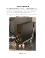
Page 7: ...G 4985 drawing shows the RCOM 100 in the mounting tray with dimensions Page 2 of ENG 4985 shows the RCOM 100 center of gravity Prepare the mounting location to provide a good electrical bond between the mounting tray and the airframe If the removal of paint is required to obtain this electrical bond it should be done Prepare the mounting holes and secure the equipment mounting tray Place the RCOM ...

Page 8: ...facturer In addition to the location for the mounting the aircraft surface should be prepared by removing the paint where the antenna will attach to the skin Note The bond between the airframe and the antenna needs to be 10 milliohms or less Make sure that this antenna has a spatial separation of 45dB between it and any GPS antennas as defined above You should note and mark on the antenna which te...

Page 9: ...ARNAV Systems Inc 8 Document No 570 8050B 27 November 2002 Antenna Mount Outside View ...

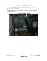
Page 10: ...TA 12 Dialer Refer to the NAT PTA12 000 Installation and Service Manual SM55 in Appendix B for dimensions and mounting information For locating the PTA 12 refer to the picture below The PTA 12 is mounted in the panel just above the pilots left knee PTA 12 Dialer Install Location ...

Page 11: ...d VC28 Mounting The VC28 is just to the left of the RCOM 100 and is mounted to the equipment shelf Route Coax Cables for Tx and Rx Refer to Drawing ENG 5021 to see Coax routing location The coax pair routes from the Antenna down the right side of the aircraft then back to the RCOM 100 Make sure the correct coax for the Tx and Rx channels is selected and make sure they are attached to the correct a...

Page 12: ... below the doorframe to the area behind the control panel where the wires connect to the audio panel and PTA 12 Assured that the cables are secured and avoid routing near any control cables or moving surfaces Connect the aircraft equipment per wire diagram ENG 5024 Add a 5 amp circuit breaker for the RCOM 100 and a 1 amp circuit breaker for the PTA 12 The telephone audio can come from either the P...

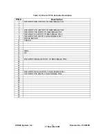
Page 13: ...UTPUT TO DB9 FEMALE PIN 8 6 DATA PORT TXD INPUT TO DB9 FEMALE PIN 3 7 DATA PORT RI OUTPUT TO DB9 FEMALE PIN 9 8 DATA PORT RFR INPUT TO DB9 FEMALE PIN 7 9 POWER RETURN 10 POWER 11 12 13 14 15 RING 16 TIP 17 18 19 DATA PORT SIGNAL RETURN TO DB9 FEMALE PIN 5 20 21 22 23 24 25 DATA PORT RLSD OUTPUT TO DB9 FEMALE PIN 1 26 DATA PORT DTR INPUT TO DB9 FEMALE PIN 4 27 28 29 30 31 32 33 34 35 36 37 ...

Page 14: ... can be transmitted Sending the followed by a delay of longer than 1 second then the ATH terminates the connection Packet Services The data connection is established by the computer issuing a dialing command ATD 777 enter This starts a PPP session using the TCP IP protocol Sending the followed by a delay of longer than 1 second then the ATH terminates the connection The PPP connection using TCP IP...

Page 15: ...st Using the PTA 12 with Phone capable audio panel Move the aircraft out of any hanger or enclosed area so the antenna has a clear view of the sky The RCOM 100 is taken off hook by selecting TEL on the audio panel After selecting TEL there will be a dial tone Press the Hook switch on the PTA 12 then dial the number to place a call Dial a phone number and verify that you are able to connect with th...

Page 16: ...n front of the area code Data Port Test With the aircraft out of any enclosed hanger hook up a laptop computer to the Data Port Assumes that you have terminated the Data Port with a DB 9 female connector Using a terminal emulator program with the serial port set up for 19200 8 n 1 You should be able to type AT ENTER and get an OK back from the RCOM 100 This verifies that the data port is wired cor...

Page 17: ...ARNAV Systems Inc 16 Document No 570 8050B 27 November 2002 Appendix A Drawings ...

Page 18: ...N CONTAINED IN THIS DRAWING IS THE SOLE PROPERTY OF ARNAV SYSTEMS INC ANY REPRODUCTION IN PART OR WHOLE WITHOUT THE WRITTEN PERMISSION OF ARNAV SYSTEMS INC IS PROHIBITED REVISIONS REV DESCRIPTION DATE APPROVED ARNAV SYSTEMS INC ENG 7069 DECIMAL XX 010 XXX 005 XXXX 0010 ANGULAR 5 JR 10 08 02 1 1 16923 MERIDIAN EAST PUYALLUP WA 98373 B ORIGINAL RELEASE A 452 0161 MOUNTING FRAME ASSY ATR 10 08 02 TIT...

Page 19: ...LUP WA 98373 OUTLINE MOUNTING TRAY INSTALL RCOM 100 DWG NO ARNAV SYSTEMS INC ENG 4985 SHEET 1 of 2 B REV A CONTRACT NO PROPRIETARY INFORMATION ARNAV SYSTEMS INC May Not Be Reproduced Or Disclosed Without Prior Written Consent of REVISIONS ORIGINAL RELEASE 01 15 02 DR LWRGH CK APR DATE DESCRIPTION REV GH FOR MOUNTING USE 8 32X3 8 PAN HEAD PHILLIPS SCREW 8 PLCS NOT SUPPLIED OUTLINE OF PLUG Tx Rx 1 6...

Page 20: ... TRAY INSTALL RCOM 100 THE INFORMATION CONTAINED IN THIS DRAWING IS THE SOLE PROPERTY OF ARNAV SYSTEMS INC ANY REPRODUCTION IN PART OR WHOLE WITHOUT THE WRITTEN PERMISSION OF ARNAV SYSTEMS INC IS PROHIBITED ARNAV SYSTEMS INC ENG 4985 16923 MERIDIAN EAST PUYALLUP WA 98373 REVISIONS SEE SHEET 1 A TITLE ...

Page 21: ......

Page 22: ...S C 5541 10 G s COLOR GLOSS WHITE 17925 PER FED STD 595B LENGTH FINISH WEIGHT HEIGHT LIGHTNING FREQUENCY IMPEDANCE POLARIZATION AXIAL RATIO POWER HANDLING GAIN ANTENNA VSWR SKYDROL RESISTANT ENAMEL 7 85 INCHES 199 4 mm 16 5 OUNCES 468 GRAMS BASE IRIDITE PER AMS C 5541 88 INCH 22 3 mm DC GROUNDED 3 0 dB ZENITH J1 Tx 60 WATTS GAIN AT Tx 1610 2 0 1 Gavg 1 dBic 10 0 90 50W LHCP 3 0 INCHES 76 2 mm WIDT...

Page 23: ...NCES ARE DECIMALS ANGULAR XX 010 XXX OO5 XXXX 0010 MATERIAL FINISH DO NOT SCALE DRAWING ITEM NO PART OR IDENTIFYING NO NOMENCLATURE OR DESCRIPTION MATERIAL SPECIFICATION QTY REQD PARTS LIST THE INFORMATION CONTAINED IN THIS DRAWING IS THE SOLE PROPERTY OF ARNAV SYSTEMS INC ANY REPRODUCTION IN PART OR WHOLE WITHOUT THE WRITTEN PERMISSION OF ARNAV SYSTEMS INC IS PROHIBITED REV DESCRIPTION REVISIONS ...

Page 24: ...ISSUED UNLESS OTHERWISE SPECIFIED DIMENSIONS ARE IN INCHES TOLERANCES ARE DECIMALS ANGULAR XX 010 XXX OO5 XXXX 0010 MATERIAL FINISH DO NOT SCALE DRAWING ITEM NO PART OR IDENTIFYING NO NOMENCLATURE OR DESCRIPTION MATERIAL SPECIFICATION QTY REQD PARTS LIST THE INFORMATION CONTAINED IN THIS DRAWING IS THE SOLE PROPERTY OF ARNAV SYSTEMS INC ANY REPRODUCTION IN PART OR WHOLE WITHOUT THE WRITTEN PERMISS...

Page 25: ...ALE SIZE CAD FILE DWG NO A SHEET OF REV DATE APPROVALS DRAWN CHECKED PROJ ENGR ISSUED THE INFORMATION CONTAINED IN THIS DRAWING IS THE SOLE PROPERTY OF ARNAV SYSTEMS INC ANY REPRODUCTION IN PART OR WHOLE WITHOUT THE WRITTEN PERMISSION OF ARNAV SYSTEMS INC IS PROHIBITED REV DESCRIPTION REVISIONS DATE APPROVED ORIGINAL RELEASE 11 27 02 JR 11 27 02 16923 MERIDIAN EAST PUYALLUP WA 98373 RCOM 100 ANTEN...

Page 26: ...ROJ ENGR ISSUED UNLESS OTHERWISE SPECIFIED DIMENSIONS ARE IN INCHES TOLERANCES ARE DECIMALS ANGULAR XX 010 XXX OO5 XXXX 0010 MATERIAL FINISH DO NOT SCALE DRAWING ITEM NO PART OR IDENTIFYING NO NOMENCLATURE OR DESCRIPTION MATERIAL SPECIFICATION QTY REQD PARTS LIST THE INFORMATION CONTAINED IN THIS DRAWING IS THE SOLE PROPERTY OF ARNAV SYSTEMS INC ANY REPRODUCTION IN PART OR WHOLE WITHOUT THE WRITTE...

Page 27: ...ARNAV Systems Inc 17 Document No 570 8050B 27 November 2002 Appendix B PTA 12 Install Manual ...

Page 28: ......

Page 29: ......

Page 30: ......

Page 31: ......

Page 32: ......

Page 33: ......

Page 34: ......

Page 35: ......

Page 36: ......

Page 37: ......

Page 38: ......

Page 39: ......

Page 40: ......

Page 41: ......

Page 42: ......

Reviews: