background image

ARRIS FPV250 Assembling User Manual 


Thank you for purchasing ARRIS FPV250 FPV Racing Quad copter. Here is a simple 
assembling manual to assemble it.   
 
 
Before we start, please prepare the following tools: 
 
1.5mm screw driver x 1 
2.0mm screw driver x 1 
3.0mm sleeve x 1 
Scissors x 1 
Tweezers x 1 
Thread Lock 


Summary of Contents for FPV250

Page 1: ...r purchasing ARRIS FPV250 FPV Racing Quad copter Here is a simple assembling manual to assemble it Before we start please prepare the following tools 1 5mm screw driver x 1 2 0mm screw driver x 1 3 0mm sleeve x 1 Scissors x 1 Tweezers x 1 Thread Lock ...

Page 2: ...1 Installation of the Frame 1 1 The picture below is the all the plate of the FPV250 Install the damper balls to the vibration damper plate ...

Page 3: ...1 2 Install the vibration damper plate to the battery plate The picture below is battery plate and vibration damper plate It should be look like this after you assemble it ...

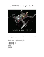
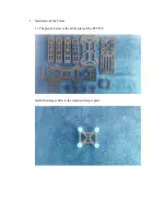
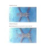
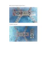
Page 4: ...1 3 Install the arms Use M3 x 12 screws on the arm like the picture below ...

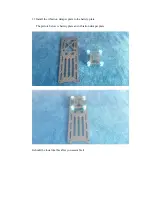
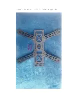
Page 5: ...1 4 Put the red aluminum column on the screws ...

Page 6: ...1 5 Install the lower plate 1 6 Install the landing skid Prepare the landing skid here we need to use M3 x 6 screws and M3 nut ...

Page 7: ...kid to the its position and use the screw to tighten it For the BNF due to the package limitation we changed the landing skid to the rubber one as below For this one we use the M3 x 12 screws with M3 nut to assemble it ...

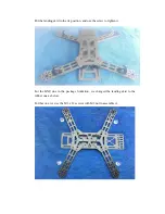
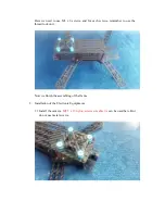
Page 8: ...1 7 Install the Aluminum column In this step we need to use the thread lock and M3 x 6 screws ...

Page 9: ...Install the aluminum column on the center frame by M3 x 6 screws and use some thread lock 1 8 Install the camera fixed plate Prepare the parts ...

Page 10: ...Put the camera fixed plate in front part as below 1 9 Install the upper plate ...

Page 11: ...r each screws remember to use the thread lock on it Now we finish the assembling of the frame 2 Installation of the Electronic Equipments 2 1 Install the camera M2 5 x 12 nylon screws or cable tie can be used here But do not use metal screws ...

Page 12: ...ounting 2 2 Install the motors Here we take the ARRIS 1806 2300KV brushless motor as example For CW motor the cap is black for the CCW motor the cap is silver please pay attention to it when you do it And the screws used to install the motor are M2 x 4 ...

Page 13: ......

Page 14: ...2 3 Solder the motor with ESC Cut off the motor wire just leave 1 5 to 2 CM length will be OK Cut off the extra wires of the ESC like the pictures below ...

Page 15: ...M heat shrink tube on the motor wire Solder the motor with ESC For the black cap CW motor the wire is one to one correspondence with the ESC wire For the CCW motor you need to change any two of the wire and solder them and then the heat shrink tube Please check the wire diagram in the following picture ...

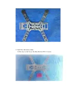
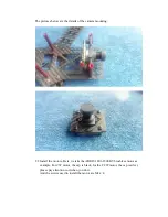
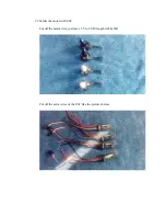
Page 16: ...2 4 Use the M2 x 6 screws to mount the motor to the frame remember to use the thread lock ...

Page 17: ...For the ESC use the 3M double side tape to paste it on the arm And pass the ESC wire through the arm ...

Page 18: ...he lower plate All the red wires put in one side and all the black wires put in the other side and tight them by the cable tie Here we need to add two pairs of wires one is the JST plug it used to power the video TX the other is main power wires it used to power the quad Please look at the following picture ...

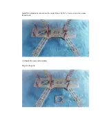
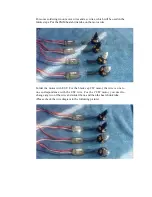
Page 19: ...Cut off the extra wires ...

Page 20: ...Solder them one color to one color correspondence like the picture below Fixed the main power wire by cable tie ...

Page 21: ...On the other side tighten the ESC by cable tie on the arm Solder the XT60 connector Pay attention to the and the red is and the black is ...

Page 22: ...l the CC3D flight controller Paste the CC3D flight controller on the lower plate by 3M double side tape It should be not crooked or it will influence the future flight Connect the ESC wire like the below diagram ...

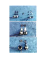
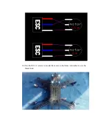
Page 23: ...Here is the ESC plugged well on the flight controller Arrange the long ESC wires ...

Page 24: ...Here we finished the assembling Next you need to set the settings on the CC3D software with your radio you can check another manual ...

Reviews: