background image


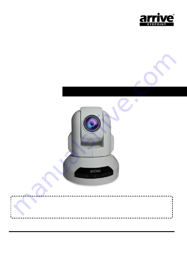
Arrive EyePoint

TM

AEP-3030


Please note the serial number of your purchased product for future reference:

Model No.: _________________        Serial No.:___________________________________________

USER MANUAL

AEP-3030-804-001

AEP-3030-UPTZ

USB 3.0 HD CAMERA

Summary of Contents for EyePoint AEP-3030

Page 1: ... 3030 Please note the serial number of your purchased product for future reference Model No _________________ Serial No ___________________________________________ USER MANUAL AEP 3030 804 001 AEP 3030 UPTZ USB 3 0 HD CAMERA ...

Page 2: ... Arrive Systems Inc All Rights Reserved 2 We reserve the right to introduce changes after the printing of this document Please refer to our website www arrivesys com for updated documentation and information ...

Page 3: ... 2014 Arrive Systems Inc All Rights Reserved 3 CONTENTS 1 INTRODUCTION 9 2 FEATURES AND SPECIFICATIONS 9 3 INSTALLING THE DEVICE 12 4 USING THE DEVICE 15 5 CONNECTING THE CAMERA 21 6 TROUBLESHOOTING 25 ...

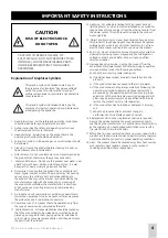
Page 4: ... not likely to be walked on or pinched by items placed upon or against them paying particular attention to cords at plugs convenience receptacles and the point where they exit from the product 12 Lightning For added protection for this product during a lightning storm or when it is left unattended and unused for long periods of time unplug it from the ethernet and or from the power socket This wil...

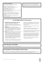
Page 5: ... A digital devices Compliance with these requirements provides a reasonable level assurance that your use of this product in a residential environment will not result in harmful interference with other electronic devices This equipment generates uses radio frequencies and if not installed and used according to the instructions found in the user manual may cause interference harmful to the operatio...

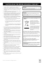
Page 6: ...ng to use this unit for long periods of time disconnect the cable from the ethernet and or power sockets to prevent fire 13 When disconnecting any cable grasp the plug do not pull the cable 14 Do not clean this unit with chemical solvents this might damage the finish Use a clean or dry cloth 15 Do not attempt to modify or fix this unit Contact qualified ARRIVE service personnel when any service is...

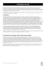
Page 7: ...UT OF THE USE OR INABILITY TO USE THIS MANUAL EVEN IF ARRIVE OR ITS SUPPLIERS HAVE BEEN ADVISED OF THE POSSIBILITY OF SUCH DAMAGES ALL TRADEMARKS AND INFORMATION ARE OWNED BY THE RESPECTIVE OWNERS OF THE TRADEMARKS AND INFORMATION WHETHER ACKNOWLEDGED OR NOT IN THIS MANUAL ARRIVE DOES NOT CLAIM ANY OWNERSHIP OF ANY TRADEMARK OR TRADENAME MENTIONED IN THE INFORMATION EXCEPT FOR THE ARRIVE TRADENAME...

Page 8: ...30 UPTZ this unit device About Trademarks All other trademarks are owned by their respective owners whether acknowledged or not in this manual Specifications of this unit and contents of this document are subject to change without notice ARRIVE does not accept any liability for any loss or damage resulting from any use of this unit the warranty covers this unit only ...

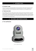
Page 9: ...030 UPTZ comes from the family of USB 3 0 super speed HD cameras from Arrive It offers unparalleled clarity and resolution for a host of applications irrespective of room sizes and light conditions They are ideal solutions for video conferencing distance learning training meeting courtroom and any other application that involves high quality color video cameras with the flexibility of remote opera...

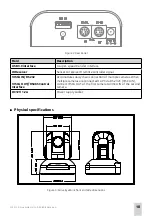
Page 10: ...R remote controller signal VISCA IN RS232 VISCA OUT RS485 Control Interface Accomodates daisy chain connection of multiple cameras When multiple cameras are connected to PC via RS 232C VISCA IN connect VISCA OUT of the first camera to VISCA IN of the second camera DC12V 1 2A Power supply socket Physical specifications Figure 3 Arrive EyePoint front and side dimensions ...

Page 11: ...mage Sensor Sensor 1 3 color CMOS 2 1 M compatible Minimum illumination 1Lux at F1 8 White Balance Auto Manual Gain Control Auto Back light compensation ON OFF Electronic shutter 1 5 1 4000S S N Ratio 50db Lens Focus Auto Iris Auto Manual Lens 10 X Optical Zoom 1 3 6 model f 5 50 0mm F2 0 2 8 Horizontal View 50 degrees Video Output USB 3 0 UY2 Video format YUY4 1920x1080 30p Control Decoder EIA RS...

Page 12: ...can Supported Boundary Scan 0 359degrees Programable Remoter Control IR Wireless remote control P T Z Power DC12V 10 1 2A Operation Temperature 10oC 60oC Environmental humidity 0 95 RH non condensaion Length X width X height 124 x 120 x 145mm Net 220 x 175 x 220mm Package Weight 800g Net 1300g Package Mounting Desktop Ceiling Wall mount Standard Tripod 3 INSTALLING THE DEVICE Package contents HD C...

Page 13: ...Rights Reserved 13 Bracket installation STEP 1 STEP 2 STEP 3 STEP 4 Figure 4 Bracket Installation After the bracket is fixed to the camera base the camera can be installed on the ceiling wall or any flat surface as per requirement ...

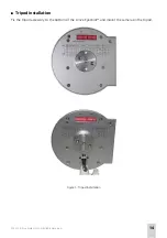
Page 14: ... 2014 Arrive Systems Inc All Rights Reserved 14 Tripod installation Fix the tripod accessory to the bottom of the Arrive EyePoint and mount the camera on the tripod Figure 5 Tripod Installation ...

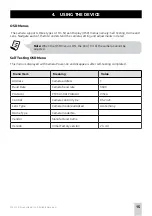
Page 15: ...en the OSD menu is ON the Pan Tilt of the camera cannot be adjusted Self Testing OSD Menu This menu is displayed with Camera Power on and disappears after self testing completed Menu Item Meaning Value Address Camera address 1 Baud Rate Camera baud rate 9600 Protocol PTZ Control Protocol VISCA Control Camera control type RS 232C Lens Type Camera module adopted Acute Sony Dome Type Camera model No ...

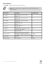
Page 16: ...ange 1 63 30 Tilt Speed Adjustable tilt movement speed Range 1 63 30 Scan Speed Adjustable pan movement speed Range 1 63 6 Tour Path Optional tour path Range 1 4 1 Tour Dwell Tour duration time Range 1 60 5 Proportion Enable disable speed match function Possible values ON OFF ON Auto Rev Image auto flip Vlaues P positive N inverted OFF P Frame Format 1080p 30 1080p 25 1080p 24 1080i 60 1080i 50 72...

Page 17: ...ode Manual PAE AAE SAE PAE Aperture mode F1 8 F11 F1 8 Shutter speed Shutter speed range 1 5 1 4000 1 5 Ev correction 2 1 66 1 33 1 0 66 0 33 0 0 33 0 66 1 1 33 1 66 2 0 ISO sensitivity Auto Manual Auto Manual setup ISO80 ISO100 ISO200 ISO400 ISO800 ISO1000 IS080 Flicker reduction ON OFF ON White balance Auto Custom Manual Daylight Cloudy Shade FLW FLN FLD Tungsten Auto Digital effect Normal Sepia...

Page 18: ... 2014 Arrive Systems Inc All Rights Reserved 18 Device Remote Control Figure 6 Remote control 1 2 3 4 5 6 7 8 9 10 11 ...

Page 19: ...Choose the preset position Set Set the preset position 4 Zoom Fast Zoom Fast Increase the Zoom In speed Increase Zoom Out speed 5 Pan Tilt control Move camera upwards Move camera downwards Move camera left Move camera right Enable Pan movement scanning 6 Auxiliary Freeze Image Freeze BL Backlight compensation WB White Balance AE Auto Exposure DZOOM Digital Zoom HDMI N A DVI N A Format N A ...

Page 20: ...peed Reduce Zoom out speed 10 Lens Focus Auto Auto focus Manual Manual focus Far Far end lens zoom Near Near end lens zoom 11 Pan Tilt Function area L Limit Set left limit points for boundary scanning Scan Enable scanning automatically R Limit Set right limit point for boundary scanning Home Home position of camera Tour Enable touring Rev Image up side down option ...

Page 21: ...VISCA RS 232C IN Reference 1 2 3 5 6 7 8 VISCA RS 232C IN Figure 7 VISCA RS 232 C IN Pin S N Function 1 DTR IN 2 DSR IN 3 TXD IN 4 GND 5 RXD IN 6 GND 7 IR Commander Signal OUTPUT 8 NO Connection VISCA Out Reference 1 2 3 5 6 7 8 VISCA RS 232C OUT Figure 8 VISCA RS 232C OUT ...

Page 22: ... 8 RS 485 Pin Configuration for Connecting Camera to PC Camera Computer 9 Pin 1 DTR IN 1 CD 2 DSR IN 2 RXD 3 TXD IN 3 TXD 4 GND 4 DTR 5 RXD IN 5 GND 6 GND 6 DSR 7 IR OUT 7 RTS 8 N C 8 CTS 9 RI Camera Computer 25 Pin 1 DTR IN 1 FG 2 DSR IN 2 TXD 3 TXD IN 3 RXD 4 GND 4 RTS 5 RXD IN 5 CTS 6 GND 6 DSR 7 IR OUT 7 GND 8 N C 20 DTR ...

Page 23: ... 1 DTR OUT 1 DTR IN 2 DSR OUT 2 DSR IN 3 TXD OUT 3 TXD IN 4 GND 4 GND 5 RXD OUT 5 RXD IN 6 GND 6 GND 7 RS485 7 IR OUT 8 RS485 20 N C References Note Switch off the power supply prior to altering the DIP switch settings DIP switch settings ON DIP 1 2 3 4 5 6 ON DIP 1 2 3 4 5 6 8 7 SW1 SW2 底部拨码开关视图 Figure 9 DIP switch overview ...

Page 24: ... ON OFF OFF 6 OFF OFF OFF OFF OFF ON OFF 7 OFF OFF OFF OFF OFF OFF ON Firmware upgrading Firmware software upgrade Set SW1 DIP 8 to ON Normal Work Mode Set SW1 DIP 8 to OFF Baud rate communication protocol assignment Baud rate SW 2 DIP 1 Communication SW 2 DIP 2 Protocol SW 2 DIP 3 38400bps ON RS 485 ON PELCO D ON 9600bps OFF RS 232 OFF VISCA OFF IR Remote control Input settings R C Address SW 2 D...

Page 25: ...re setting Check the connection between video cable camera and monitor fix the connector on each end Check and rectify the exposure settings Unable to Pan Tilt and Zoom camera OSD Menu is active Pan and tilt range is limited Exit the OSD Menu and then re operate Remote control is not working Mismatch between the camera select on the remote and IR select switch number Choose the right IR select num...

Page 26: ...www arrivesys com Arrive Systems Inc 6737 Katella Ave Cypress CA 90630 USA Toll Free 1 844 427 7483 USA Canada Email info arrivesys com 2014 Arrive Systems Inc All Rights Reserved ...

Reviews: