
Ascon Tecnologic - TRH-MINI - ENGINEERING MANUAL - PAG. 1
TRH-MINI
HUMIDITY AND TEMPERATURE
SENSOR
Engineering manual
19/12 - Cod.: ISTR_M_TRH-MINI_E_00_--
ASCON TECNOLOGIC S.r.l.
Viale Indipendenza 56, 27029 - VIGEVANO (PV) ITALY
TEL.: +39 0381 69871 - FAX: +39 0381 698730
http:\\www.ascontecnologic.com
e-mail: info@ascontecnologic.com
FOREWORD
D
D
This manual contains the information necessary for the
installation of the product, we therefore recommend that
the utmost attention is paid to the following instructions
and to save it.
This document is exclusive property of Ascon Tecnologic which
forbids any reproduction and disclosure, even in part, of the
document, unless expressly authorized. Ascon Tecnologic
reserves the right to make any formal or functional changes at
any moment and without any notice.
D
D
Ascon Tecnologic and its legal representatives do not as-
sume any responsibility for any damage to people, things or
animals deriving from violation, wrong or improper use or
in any case not in compliance with the instrument features.
D
D
Whenever a failure or a malfunction of the device
may cause dangerous situations for persons, thing
or animals, please remember that the plant must be
equipped with additional electromechanical devices
which will guarantee safety.
Disposal
The appliance (or the product) must be
disposed of separately in compliance
with the local standards in force on
waste disposal.
INSTRUMENT DESCRIPTION
General description
The Humidity and Temperature sensor adopt high quality digital
sensors, with reliable performance, high precision, small year
drift, fast response. It is suitable for temperature and humidity
measurement of communication rooms, offices, workshops,
warehouses, hospitals, HVAC, and building automation etc..
The Relative Humidity and the Temperature measurements can be
read through the RS485 Modbus RTU c
o
mmunications port.
The sensor can be mounted horizontally (on the ceiling) or verti-
cally (on the wall) using 2 screws or a DIN rail. The connections
are really easy: only 4 wires to complete the installation.
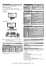
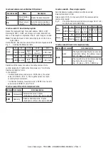
Instrument description
Power supply: 8... 24 DC
Range: -20... +80°C, 0... 100% RH
TRH-MINI
GND VDC B A
3
2
1
1. +8... 24 VDC
Power terminal;
2. GND
Power supply ground terminal;
3. A, B
RS485 Modbus RTU terminals.
INSTALLATION INFORMATION
Mounting requirements
This instrument is intended for permanent installation, for indoor
use only, in an electrical panel which encloses the rear housing,
exposed terminals and wiring on the back.
Select a mounting location having the following characteristics:
1.
It should be easily accessible;
2.
There is minimum vibrations and no impact;
3.
There are no corrosive gases;
4.
There are no water or other fluids (i.e. condensation).
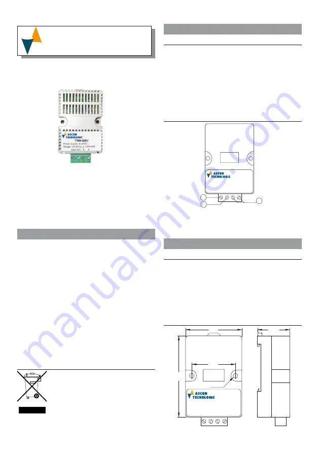
Dimensions
Power supply: 8... 24 DC
Range: -20... +80°C, 0... 100% RH
TRH-MINI
GND VDC B A
45
28
65
35
Ø3.5


