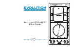
Aspen Avionics EFD1000 Dual EFI, Pilot'S Manual
The Aspen Avionics EFD1000 Dual EFI is a state-of-the-art electronic flight instrument. Pilots can access the Pilot's Manual for this product through a free download available at 88.208.23.73:8080. This comprehensive manual provides detailed instructions on how to operate and maximize the features of the EFD1000 for a smooth and efficient flight experience.
Share
Download


Reviews:
No comments
Related manuals for EFD1000 Dual EFI

M 1000 VC
Brand: Tecnodom Pages: 68
microLink
Brand: uAvionix Pages: 6
Apollo GX 50
Brand: II Morrow Pages: 207
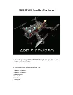
FPV250
Brand: Arris Pages: 24
G500
Brand: Garmin Pages: 104

FDU-268
Brand: Barco Pages: 2

ST3400
Brand: Sandel Pages: 116

DW-CN-0660
Brand: Omcan Pages: 12

50082
Brand: Omcan Pages: 20

44639
Brand: Omcan Pages: 20

RC Allen Instruments RCA 2610-2
Brand: Kelly Manufacturing Pages: 18


