
EP2C612D16FM / EP2C612D16FM-N
Quick Installation Guide
www.asrockrack.com
No. Description
No. Description
1
USB 2.0 Ports (USB_1_2)
5
LAN RJ-45 Port (LAN1)
2
Serial Port (COM1)
6
LAN RJ-45 Port (LAN2)
3
VGA Port (VGA1)
7
LAN RJ-45 Port (IPMI_LAN)
4
UID Switch (UID)
8
USB 3.0 Ports (USB3_1_2)
4
2
P/N: 15G065016100AK V1.0
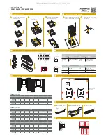
Install the Server Board
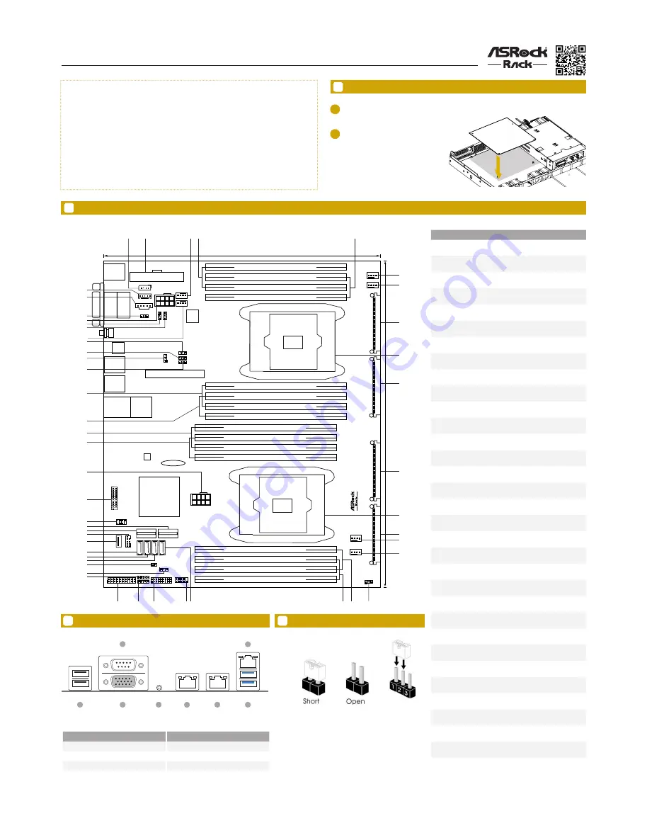
Motherboard Layout
Jumper Cap On/Off
The server board User's Manual is available for download from the ASRock Rack's official website
at http://www.asrockrack.com.
Take note of the following precautions before you install server board components or change any
server board settings.
1.
Unplug the power cord from the wall socket before touching any components.
2.
To avoid damaging the server board’s components due to static electricity, NEVER place your
server board directly on the carpet or the like. Also remember to use a grounded wrist strap or
touch a safety grounded object before you handle the components.
3.
Hold components by the edges and do not touch the ICs.
4.
Whenever you uninstall any component, place it on a grounded anti-static pad or in the bag
that comes with the component.
5.
When placing screws into the screw holes to secure the server board to the chassis, please do
not over-tighten the screws! Doing so may damage the server board.
1
1
Insert the server board into the chassis.
2
Affix the screws clockwise into the
mounting holes in all of the corners of
the server board.
Do not over-tighten the screws
When the jumper cap is placed on the pins, the
jumper is “Short”. If no jumper cap is placed on the
pins, the jumper is “Open”.
The illustration shows a 3-pin jumper whose pin1
and pin2 are “Short” when a jumper cap is placed on
these 2 pins.
I/O Panel
26.7cm (10.5 in)
3
0
.5
c
m (
1
2
.0
in
)
ATXPWR1
1
2
1
V
G
A
1
C
O
M
1
Top:
IPMI_LAN
USB 3.0
T: USB2
B: USB1
DDR4_H2 (64 bit, 288-pin module, White)
DDR4_H1 (64 bit, 288-pin module, Blue)
DDR4_G2 (64 bit, 288-pin module, White)
DDR4_G1 (64 bit, 288-pin module, Blue)
1
PSU_SMB1
1
E
P
2
C
6
1
2
D
1
6
F
M
Intel
C612
64Mb
BIOS
BMC
ROM
DDR4_E1 (64 bit, 288-pin module, Blue)
DDR4_E2 (64 bit, 288-pin module, White)
DDR4_F1 (64 bit, 288-pin module, Blue)
DDR4_F2 (64 bit, 288-pin module, White)
DDR4_A1 (64 bit, 288-pin module, Blue)
DDR4_A2 (64 bit, 288-pin module
)
, White
DDR4_B1 (64 bit, 288-pin module
)
, Blue
DDR4_B2 (64 bit, 288-pin module
)
, White
DDR4_D2 (64 bit, 288-pin module, White)
DDR4_D1 (64 bit, 288-pin module, Blue)
DDR4_C2 (64 bit, 288-pin module, White)
DDR4_C1 (64 bit, 288-pin module, Blue)
R
o
H
S
LAN1
LAN2
CMOS
Battery
MEZZ_MB2
IPMB_1
BMC_SMB_1
1
1
ATX12V3
REAR_FAN1
REAR_FAN2
CPU2_FAN1
FRNT_FAN1
1
1
1
1
ATX12V2
AUX_PANEL1
PANEL1
SPEAKER1
TPM1
USB_3_4
C
O
N
3
0
C
O
N
3
1
C
O
N
2
8
C
O
N
2
9
3 4
5
6
7
8
10
11
13
16
18
19
21
22
23
24
25
26
27
29
30
31
35
37
38
39
40
UID
1
ME_RECOVERY1
20
USB3 TYPE A
28
32
33
9
12
1
SATA_SGPIO2
34
CPU2
CPU1
CPU1_FAN1
FRNT_FAN2
1
PECI1
1
USB3_3_4
1
USB 2.0
T: USB2
B: USB1
1
1
FRONT_LED_LAN34
SATA0-3
sSATA0-3
NMI_BTN1
SATA4
SATA5
M_SATA_0
M_SATA_1
Chassis ID1
Chassis ID0
14
15
17
36
46
41
42
43
44
45
Super
I/O
1
1
1
1
1
47
48
49
50
51
Chassis ID2
NCSI_SEL1
PMBUS_SEL_ALT1
PMBUS_SEL_CLK1
PMBUS_SEL_DAT1
No.
Description
1
Intelligent Platform Management Bus header
(IPMB_1)
2
ATX Power Connector (ATXPWR1)
3
Rear Fan Connector (REAR_FAN1)
4
2 x 288-pin DDR4 DIMM Slots (DDR4_H1, DDR4_
G1, Blue)
5
2 x 288-pin DDR4 DIMM Slots (DDR4_H2, DDR4_
G2, White)
6
Front Fan Connector (FRONT_FAN1)
7
CPU 2 Fan Connector (CPU2_FAN1)
8
PCIE Switch Board Connector (CON30) (CPU2)*
9
LGA 2011 CPU Socket (CPU2)
10
PCIE Switch Board Connector (CON31) (CPU2)*
11
PCIE Switch Board Connector (CON28) (CPU1)*
12
LGA 2011 CPU Socket (CPU1)
13
PCIE Switch Board Connector (CON29)(CPU1)*
14
CPU 1 Fan Connector (CPU1_FAN1)
15
Front Fan Connector (FRONT_FAN2)
16
CPU PECI Jumper (PECI1)
17
2 x 288-pin DDR4 DIMM Slots (DDR4_A2, DDR4_
B2, White)
18
2 x 288-pin DDR4 DIMM Slots (DDR4_A1, DDR4_
B1, Blue)
19
SATA3 Connector (M_SATA_1), White
20
System Panel Header (PANEL1)
21
Auxiliary Panel Header (AUX_PANEL1)
22
Speaker Header (SPEAKER1)
23
TPM Header (TPM1)
24
Front Lan LED Connector (FRNT_LAN34)(For Mez-
zanine Card)
25
ME Recovery Jumper (ME_RECOVERY1)
26
Non Maskable Interrupt Button (NMI_BTN1)
27
SATA3 Connector (M_SATA_0), White
28
SATA3 Connector (SATA5), White
29
SATA3 Connector (SATA4), White
30
Vertical Type A USB 3.0 (USB3_5)
31
USB 2.0 Header (USB_3_4)
32
mini SAS Connector (SATA0-3)
33
mini SAS Connector (sSATA0-3)
*For EP2C612D16FM only
6
5
3
2
4
1
7
8
*15G065016100AK*
3
All manuals and user guides at all-guides.com
all-guides.com


