background image

®

ASSA ABLOY

ElectroLynx® is a registered trademark of ASSA ABLOY Inc.

Copyright © 2014 Corbin Russwin, Inc. All rights reserved.

Reproduction in whole or in part without the express written 

permission of Corbin Russwin, Inc. is prohibited.

1

Attention Installer

A

ccess


800

®

C A U T I O N

DOOR MUST REMAIN OPEN

DURING INSTALLATION.

USE DOOR STOP.

TEST

FOR PROPER

OPERATION

BEFORE

CLOSING

DOOR

For installation assistance contact Corbin Russwin Inc., at 1-800-810-WIRE (9473)

FM335   10/18

Please read these instructions carefully to prevent missing important steps.

Please Note: 

Improper installation may result in damage to the lock and void the factory warranty.

Important: 

The accuracy of the door preparation is critical for proper functioning and security of this lock.

                   Misalignment can cause premature wear and a lessening of security. 

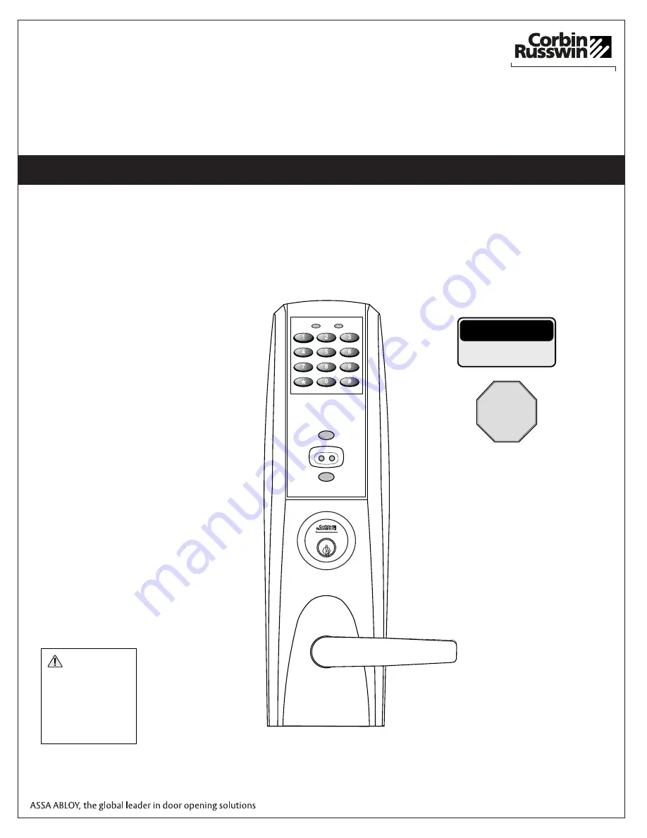
Installation Instructions

Mortise Lockset

For ML20800 TCWI1/TCIP1 Series

In U.S.:
Corbin Russwin, Inc.
225 Episcopal Road
Berlin, CT 06037 USA
www.corbinrusswin.com

In Canada:
ASSA ABLOY Door Security Solutions Canada
160 Four Valley Drive
Vaughan, Ontario, Canada L4K4T9
www.assaabloy.ca

®

ASSA ABLOY

 WARNING

This product can expose  

you to lead which is  

known to the state of  

California to cause cancer 

and birth defects or other 

reproductive harm. For 

more information go to  

www.P65warnings.ca.gov.

08/2018

Summary of Contents for Corbin Russwin Access 800 Series

Page 1: ... Improper installation may result in damage to the lock and void the factory warranty Important The accuracy of the door preparation is critical for proper functioning and security of this lock Misalignment can cause premature wear and a lessening of security Installation Instructions Mortise Lockset For ML20800 TCWI1 TCIP1 Series In U S Corbin Russwin Inc 225 Episcopal Road Berlin CT 06037 USA ww...

Page 2: ...ctroLynx is a registered trademark of ASSA ABLOY Inc Copyright 2014 Corbin Russwin Inc All rights reserved Reproduction in whole or in part without the express written permission of Corbin Russwin Inc is prohibited 2 ...

Page 3: ...otection against harmful interference in a residential installation This equipment generates uses and can radiate radio frequency energy and if not installed and used in accordance with the instructions may cause harmful interference to radio communications However there is no guarantee that the interference will not occur in a particular installation If this equipment does cause harmful interfere...

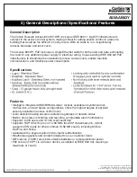
Page 4: ...ing IEEE 802 3af PoE infrastructure to streamline the installation process reduce costs enable real time communication and minimize power consumption Intelligent integrated ANSI BHMA Grade 1 lockset available in cylindrical lock mortise lock and exit device configurations offers the highest degree of physical security available in access control locks Local decision making ensures operation regardl...

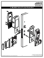
Page 5: ...rademark of ASSA ABLOY Inc Copyright 2014 Corbin Russwin Inc All rights reserved Reproduction in whole or in part without the express written permission of Corbin Russwin Inc is prohibited 5 3 ML20800 Series Product Illustration A SS A AB L OY ...

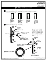
Page 6: ...se Bevel Hinges Right Open Outward RHR 7 8 1 1 2 1 8 Dia holes 2 required Slot Attach fire stop plate using self tapping screws 8 32 x 1 2 long for wood metal doors C of 1 1 2 Dia L Outside of Door Hole for ribbon cable Non Fire Rated Exterior Doors install weather conduit Hollow Doors Only Outside of Door Non Fire Rated Door Hole for ribbon cable Install conduit half with recessed panel Not For Us...

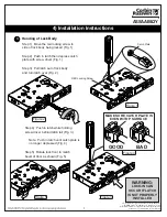
Page 7: ... screw to side of lock body being locked Fig 1 Step 2 Push in latch then depress catch plate with screw driver Fig 1 Step 3 Pull latch out of lock body and turn latch over Fig 2 Figure 1 Figure 2 Figure 3 Figure 5 Step 4 Push in latch while holding screw driver behind latch tail Fig 3 Note Push in latch until catch plate is no longer depressed Fig 4 Step 5 Rotate lock front to match bevel of door ...

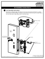
Page 8: ... Lock Assembly Instructions 4 4 Installation Instructions 2 12x1 Combination Screws Lock Body 7 64 Allen Wrench Align bevel accordingly Engage 7 64 Allen wrench onto cap screw required for Step 5 3 on page 9 Feed connector and wires through 1 25 dia wire access hole Insert lock body into mortise cutout in door and hold loosely in place with 2 12x1 lock body screws Inside of Door Feed conn through ...

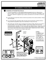
Page 9: ...from outside escutcheon through weather seal gasket if used then conduit sleeve in door not shown 3 With outside lever horizontal insert mounting posts into the door Make certain the lever spindle is properly engaged in lock see diagram and Note A below Screw cylinder into mortise lock ensuring the cylinder orientation is in the correct position see diagram below Using the 7 64 allen wrench provid...

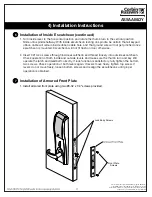
Page 10: ... Feed Trim assembly motor harness through gasket opening as shown and firmly press gasket to escutcheon aligning edge of gasket with the edge of the escutcheon Inside of door Keypad Ribbon Cable Thumb Turn C A U T I O N DOOR MUST REMAIN OPEN DURING INSTALLATION USE DOOR STOP NOTE Connectors go on only one way Do not offset connector and be sure they are completely seated 1 Remove black battery cove...

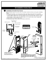
Page 11: ... hole and that ground wire will not get pinched once escutcheon is mounted Escutcheon will not fit flush on door otherwise 2 Insert 3 10 24 screws through inside escutcheon and thread loosely into outside escutcheon Check operation of both inside and outside levers and make sure the thumb turn and key still operate the latch and deadbolt correctly If lock function is satisfactory fully tighten the b...

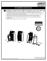
Page 12: ...screw of the battery keeper and remove the battery keeper being careful not to break the tabs at top holding it in place Fig 8A 3 Place 6 AA batteries in the compartment being careful to align polarity properly Fig 8B 4 Replace battery keeper being careful to engage tabs at top to hold it in place Fig 8A 5 Attach battery cover to inside escutcheon making sure to line up tabs with retaining slots i...

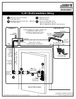
Page 13: ...connector and the Male RJ45 connector from harness to end user provided facility cable Supplied by End User PoE Switch PoE Lock Ceiling Supplied by CI C B A PoE Patch Panel Drain Wire Terminated on Rack D Ground Ring Terminal Secured to Lock Mounting Plate Drain Wire PoE Switch Rack is Terminated to Earth Ground Patch Cable PoE Panel to PoE Switch 4 Pin Molex PoE Frame harness assembly From McKinn...

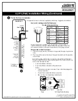
Page 14: ...o not force and do not offset connectors Be sure they are completely seated flush Cut end ceiling side PoE harness TIA 568 B Standard Wiring 1 2 3 4 5 6 7 8 Pair Number Wire PIN 1 White Blue White Blue 5 Blue 4 2 White Orange White Orange 1 Orange 2 3 White Green White Green 3 Green 6 4 White Brown White Brown 7 Brown 8 Do not confuse pair numbers with pin numbers A pair number is used for referenc...

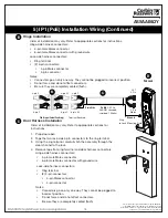
Page 15: ... may vary Refer to appropriate sections for instructions 1 Prop door open 2 Tape the two lock side 4 pin connectors to the ring terminal 3 Using the ring terminal carefully fish the assembly through the door channel to the lock 4 Remove tape from ring terminal and door harness connectors Hinge side harness connectors 4 pin male Molex connector 6 pin male Molex connector with ground wire Lock side h...

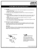
Page 16: ...colors all match 3 If door does not have an ElectroLynx type door harness cut connectors off product and hard wire or consult factory for appropriate mating harness 6 3 ElectroLynx Connector System Notes The system is designed to be installation friendly with pluggable connectors from the electric hinge through the door to the rail The only wiring required is to the loose wires on the pigtail harn...

Page 17: ... in part without the express written permission of Corbin Russwin Inc is prohibited 17 ELECTR O 6 4 Hard Powered Connections END OF INSTALLATION INSTRUCTIONS 6 ML20800 Hardwiring Instructions 120V AC Input 9V DC Power Supply McKinney QC 8 Hinge ElectroLynx Raceway Cable Lock Adapter Harness Provided TB2 TB1 E1 Escutcheon Ground TB1 TB2 ASSA ABLOY ...

Page 18: ...to cylinder and rotate There should be no friction against lock case wire harness or any other obstructions 2 The key will retract the latch key should rotate freely If the deadbolt is thrown the key will first retract the deadbolt and then the latch Inside lever retracts latch and deadbolt if provided 3 Use proximity card or PIN code set up with lock configuration tool This should unlock outside le...

Page 19: ...ctroLynx is a registered trademark of ASSA ABLOY Inc Copyright 2014 Corbin Russwin Inc All rights reserved Reproduction in whole or in part without the express written permission of Corbin Russwin Inc is prohibited 19 ...

Page 20: ...ctroLynx is a registered trademark of ASSA ABLOY Inc Copyright 2014 Corbin Russwin Inc All rights reserved Reproduction in whole or in part without the express written permission of Corbin Russwin Inc is prohibited 20 ...

Reviews: