background image

Motherboard

M2N32 WS

Professional


Summary of Contents for M2N32 WS Professional

Page 1: ...Motherboard M2N32 WS Professional ...

Page 2: ...CHANTABILITY OR FITNESS FOR A PARTICULAR PURPOSE IN NO EVENT SHALL ASUS ITS DIRECTORS OFFICERS EMPLOYEES OR AGENTS BE LIABLE FOR ANY INDIRECT SPECIAL INCIDENTAL OR CONSEQUENTIAL DAMAGES INCLUDING DAMAGES FOR LOSS OF PROFITS LOSS OF BUSINESS LOSS OF USE OR DATA INTERRUPTION OF BUSINESS AND THE LIKE EVEN IF ASUS HAS BEEN ADVISED OF THE POSSIBILITY OF SUCH DAMAGES ARISING FROM ANY DEFECT OR ERROR IN ...

Page 3: ...2 2 2 Screw holes 2 2 2 2 3 ASUS Stack Cool 2 2 3 2 2 5 Motherboard layout 2 4 2 2 4 Layout contents 2 5 2 3 Central Processing Unit CPU 2 7 2 3 1 Installing the CPU 2 7 2 3 2 Installing the heatsink and fan 2 9 2 4 System memory 2 12 2 4 1 Overview 2 12 2 4 2 Memory configurations 2 13 2 4 3 Installing a DIMM 2 15 2 4 4 Removing a DIMM 2 15 2 5 Expansion slots 2 16 2 5 1 Installing an expansion c...

Page 4: ...bootable floppy disk 4 4 4 1 3 ASUS EZ Flash 2 utility 4 5 4 1 4 Updating the BIOS 4 6 4 1 5 Saving the current BIOS file 4 8 4 1 6 ASUS CrashFree BIOS 3 utility 4 9 4 2 BIOS setup program 4 10 4 2 1 BIOS menu screen 4 11 4 2 2 Menu bar 4 11 4 2 3 Legend bar 4 12 4 2 4 Menu items 4 12 4 2 5 Sub menu items 4 12 4 2 6 Configuration fields 4 12 4 2 7 Pop up window 4 13 4 2 8 General help 4 13 4 3 Mai...

Page 5: ...ard Device Configuration 4 30 4 5 Power menu 4 34 4 5 1 ACPI Suspend Type 4 34 4 5 2 ACPI APIC Support 4 34 4 5 3 APM Configuration 4 35 4 5 4 Hardware Monitor 4 37 4 6 Boot menu 4 38 4 6 1 Boot Device Priority 4 38 4 6 2 Removable Drives 4 39 4 6 3 Hard Disk Drives 4 39 4 6 4 CDROM Drives 4 39 4 6 5 Boot Settings Configuration 4 40 4 6 6 Security 4 41 4 7 Tools menu 4 43 4 7 1 ASUS Music Alarm 4 ...

Page 6: ...ling an operating system 5 1 5 2 Support CD information 5 1 5 2 1 Running the support CD 5 1 5 2 2 Drivers menu 5 2 5 2 3 Utilities menu 5 3 5 2 4 Make Disk menu 5 5 5 2 5 Manuals menu 5 6 5 2 6 ASUS Contact information 5 7 5 2 7 Other information 5 7 ...

Page 7: ...ause harmful interference to radio or television reception which can be determined by turning the equipment off and on the user is encouraged to try to correct the interference by one or more of the following measures Reorient or relocate the receiving antenna Increase the separation between the equipment and receiver Connect the equipment to an outlet on a circuit different from that to which the...

Page 8: ... your area If you are not sure about the voltage of the electrical outlet you are using contact your local power company If the power supply is broken do not try to fix it by yourself Contact a qualified service technician or your retailer Operation safety Before installing the motherboard and adding devices on it carefully read all the manuals that came with the package Before using the product m...

Page 9: ...quence and ways of shutting down the system Chapter 4 BIOS setup This chapter tells how to change system settings through the BIOS Setup menus Detailed descriptions of the BIOS parameters are also provided Chapter 5 Software support This chapter describes the contents of the support CD that comes with the motherboard package Where to find more information Refer to the following sources for additio...

Page 10: ...ey1 Key2 Key3 If you must press two or more keys simultaneously the key names are linked with a plus sign Example Ctrl Alt D Command Means that you must type the command exactly as shown then supply the required item or value enclosed in brackets Example At the DOS prompt type the command line awdflash M2N32 WS ROM DANGER WARNING Information to prevent injury to yourself when trying to complete a ...

Page 11: ...system memory Expansion slots 2 x PCI Express x16 slots with NVIDIA SLI support at full x16 x16 speed 2 x PCI E x1 slots 2 x PCI X slots 1 x PCI 2 2 slot Scalable Link Interface SLI Supports two identical NVIDIA SLI ready graphics cards both at x16 mode Storage NVIDIA nForce 590 SLI MCP supports 1 x IDE connector for up to two Ultra DMA 133 100 devices 6 x Serial ATA 3 0 Gb s connectors support si...

Page 12: ...OS Profile overclocking configuration sharing tool ASUS C P R CPU Parameter Recall ASUS AI Booster Adjustable FSB DDR2 ratio Fixed PCI PCIe frequencies Hyper Path 3 Precision Tweaker vDIMM 25 step DRAM voltage control vCore Adjustable CPU voltage at 0 0125 V increment Stepless Frequency Selection SFS allows FSB tuning from 200 MHz up to 400 MHz at 1 MHz increment PCI Express x16 frequency allows P...

Page 13: ...n connectors 2 x IEEE 1394a connectors 1 x Parallel connector 1 x TPM connector Chassis intrusion connector Front panel audio connector CD audio in connector 24 pin ATX power connector 8 pin ATX 2 0 1 1 power connector System panel connector BIOS features 8 Mb AWARD BIOS PnP DMI 2 0 WfM2 0 SM BIOS 2 3 Manageability WOL by PME WOR by PME PXE AI NET 2 Chassis Intrusion Power requirements ATX power s...

Page 14: ...xiv ...

Page 15: ...1 Product introduction This chapter describes the motherboard features and the new technologies it supports ...

Page 16: ...ASUS M2N32 WS Professional Chapter summary 1 1 1 Welcome 1 1 1 2 Package contents 1 1 1 3 Special features 1 2 ...

Page 17: ...low If any of the above items is damaged or missing contact your retailer 1 2 Package contents Check your motherboard package for the following items Motherboard ASUS M2N32 WS Professional I O modules 1 x 2 port IEEE 1394a module 1 x 2 port USB 2 0 module Cables 9 x Serial ATA cables 5 x Serial ATA power cables for up to nine devices 1 x Ultra DMA 133 100 66 cable 1 x Floppy disk drive cable Acces...

Page 18: ...t 32 bit architecture The 64 bit architecture delivers advanced system performance faster memory access and increased productivity This motherboard provides excellent compatibility and flexibility by support either 64 bit or 32 bit architecture See page 2 7 for details DDR2 memory support The motherboard supports DDR2 memory that features data transfer rates of 800 667 533 MHz to meet the higher b...

Page 19: ...four Serial ATA 3 0 Gb s connectors three at mid board and one on the rear panel provide smart setup and hot plug function See pages 2 28 2 31 and 2 32 for details IEEE 1394a support The IEEE 1394a interface provides high speed and flexible PC connectivity to a wide range of peripherals and devices compliant to the IEEE 1394a standard The IEEE 1394a interface allows up to 400 Mbps transfer rates t...

Page 20: ...s use the PCI Express segment to provide faster data bandwidth for your wired or wireless Internet LAN and file sharing requirements See page 2 27 for details AMD Cool n Quiet Technology The motherboard supports the AMD Cool n Quiet Technology which monitors system operation and automatically adjusts CPU voltage and frequency for a cool and quiet operating environment See page 4 26 for details ...

Page 21: ...at that critical components generate See page 2 3 for details 8 Phase Power Design The ASUS 8 Phase Power Design prolongs CPU lifespan and keeps the system stable by preventing high power stress to the CPU and power supply module The design ensures high efficiency operation to generate less heat compared with conventional power solutions thus achieving cool system environment and making this mothe...

Page 22: ...he motherboard to automatically adjust the PCI Express graphics link mode to the correct frequency based on the system configuration Four additional settings are available for overclocking the PEG Link Mode See page 4 23 for details Precision Tweaker This feature allows you to fine tune the CPU memory voltage and gradually increase the memory Front Side Bus FSB and PCI Express frequency at 1MHz in...

Page 23: ...ate ASUS O C Profile The motherboard features the ASUS BIOS Profile that allows users to conveniently store or load multiple BIOS settings The BIOS settings can be stored in the CMOS or a separate file giving users freedom to share and distribute their favorite settings AI NOS Non Delay Overclocking System ASUS Non delay Overclocking System NOS is a technology that auto detects the CPU loading and...

Page 24: ...1 Chapter 1 Product introduction ...
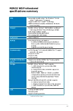
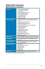
Page 25: ... Hardware information This chapter lists the hardware setup procedures that you have to perform when installing system components It includes description of the jumpers and connectors on the motherboard ...

Page 26: ...2 WS Professional Chapter summary 2 2 1 Before you proceed 2 1 2 2 Motherboard overview 2 2 2 3 Central Processing Unit CPU 2 7 2 4 System memory 2 12 2 5 Expansion slots 2 16 2 6 Jumper 2 25 2 7 Connectors 2 27 ...

Page 27: ... cord from the wall socket before touching any component Use a grounded wrist strap or touch a safely grounded object or to a metal object such as the power supply case before handling components to avoid damaging them due to static electricity Hold components by the edges to avoid touching the ICs on them Whenever you uninstall any component place it on a grounded antistatic pad or in the bag tha...

Page 28: ...ion The edge with external ports goes to the rear part of the chassis as indicated in the image below 2 2 2 Screw holes Place nine 9 screws into the holes indicated by circles to secure the motherboard to the chassis Place this side towards the rear of the chassis Make sure to unplug the power cord before installing or removing the motherboard Failure to do so can cause you physical injury and dam...

Page 29: ...motherboard comes with the ASUS Stack Cool 2 cooling solution that lowers the temperature of critical heat generating components by 20ºC The motherboard uses a special design on the printed circuit board PCB to dissipate heat that critical components generate ...

Page 30: ...AD1988B PCIEX16_1 PCIEX1_1 PCI1 CLRTC USB78 USB56 ATX12V SB_PWR EATXPWR PRI_IDE CR2032 3V Lithium Cell CMOS Power PRI_EIDE COM1 LAN1_USB12 PS 2KBMS T Mouse B Keyboard PARALLEL PORT SPDIF_O1 SPDIF_O2 LAN2_USB34 EXT_SATA4 AUDIO PCIEX16_2 PCIEX1_2 PCIX_1 PCIX_2 USB910 USB910_WFGBT TPM Socket AM2 PCIX_SPEED IE1394_2 CHA_FAN3 CHA_FAN1 SPS_FAN1 EXT_SATA1 EXT_SATA3 EXT_SATA2 SATA5 SATA3 SATA1 SATA6 SATA4...

Page 31: ...ctors Page 1 PS 2 mouse port green 2 27 2 Parallel port 2 27 3 LAN 1 RJ 45 port 2 27 4 LAN 2 RJ 45 port 2 27 5 Rear Speaker Out port black 2 27 6 Center Subwoofer port orange 2 27 7 Line In port light blue 2 27 8 Line Out port lime 2 27 9 Microphone port pink 2 28 10 Side Speaker Out port gray 2 28 11 USB 2 0 ports 1 and 2 2 28 12 USB 2 0 ports 3 and 4 2 28 13 External SATA port 2 28 14 Optical S ...

Page 32: ...ectors 10 1 pin IE1394_1 10 1 pin IE1394_2 2 33 8 CPU chassis power and Power Fan connectors 4 pin CPU_FAN 3 pin CHA_FAN1 3 pin CHA_FAN2 3 pin CHA_FAN3 3 pin CHA_FAN4 3 pin SPS_FAN1 2 34 9 Chassis intrusion connector 4 1 pin CHASSIS 2 35 10 ATX power connectors 24 pin EATXPWR 8 pin ATX12V 2 35 11 Front panel audio connector 10 1 pin AAFP 2 36 12 Internal audio connector 4 pin CD black 2 37 13 Seri...

Page 33: ...ntral Processing Unit CPU The motherboard comes with a 940 pin AM2 socket designed for the AMD Athlon 64 X2 Athlon 64 FX Athlon 64 Sempron processor Socket lever The AM2 socket has a different pinout from the 939 pin socket designed for the AMD Opteron processor Make sure you use a CPU is designed for the AM2 socket The CPU fits in only one correct orientation DO NOT force the CPU into the socket ...

Page 34: ...ith a small triangle 4 Carefully insert the CPU into the socket until it fits in place 5 When the CPU is in place push down the socket lever to secure the CPU The lever clicks on the side tab to indicate that it is locked 6 Install a CPU heatsink and fan following the instructions that came with the heatsink package Gold triangle Small triangle ...

Page 35: ...r boxed CPU heatsink and fan assembly should come with installation instructions for the CPU heatsink and the retention mechanism If the instructions in this section do not match the CPU documentation follow the latter The retention module base is already installed on the motherboard upon purchase You do not have to remove the retention module base when installing the CPU or installing other mothe...

Page 36: ...bracket lock to the retention module base A clicking sound denotes that the retention bracket is in place 4 Push down the retention bracket lock on the retention mechanism to secure the heatsink and fan to the module base Make sure that the fan and heatsink assembly perfectly fits the retention mechanism module base otherwise you cannot snap the retention bracket in place ...

Page 37: ...nnect the CPU fan cable to the connector on the motherboard labeled CPU_FAN Do not forget to connect the CPU fan connector Hardware monitoring errors can occur if you fail to plug this connector M2N32 WS PRO M2N32 WS PRO CPU fan connector CPU_FAN GND CPU FAN PWR CPU FAN IN CPU FAN PWM ...

Page 38: ...hysical dimensions as a DDR DIMM but has a 240 pin footprint compared to the 184 pin DDR DIMM DDR2 DIMMs are notched differently to prevent installation on a DDR DIMM socket The figure illustrates the location of the DDR2 DIMM sockets Channel Sockets Channel 1 DIMM_A1 and DIMM_B1 Channel 2 DIMM_A2 and DIMM_B2 M2N32 WS PRO M2N32 WS PRO 240 pin DDR2 DIMM sockets DIMM_B1 DIMM_A1 DIMM_B2 DIMM_A2 ...

Page 39: ...tions as shown then click Search Click the article titled 4GB memory installed but less memory size detected You also may check the URLs below for third party comments on this issue http dlsvr01 asus com pub ASUS mb 4GB_Rev1 pdf http www intel com support motherboards server sb cs 016594 htm For dual channel configuration the total size of memory module s installed per channel must be the same DIM...

Page 40: ...512U648 C4 Hynix HY5PS12821F C4 Unbuffer Transcend TS128MLQ64V5J SEC K4T51083QC Unbuffer Micron MT16HTF12864AY 53EA1 Micron 4MAII D9CRZ 2048Mbytes Unbuffer Kinston KVR533D2N4 2G Elpida E1108AA 5C E SIZE Type Vendor Module Chip Vendor Chip Component 256Mbytes Unbuffer Hynix HYMP532U64AP6 Y5 AA Hynix HY5PS121621AFP Y5 Unbuffer Micron MT8HTF3264AY 667B5 4SB42D9CZM Unbuffer Samsung M378T3253FZ0 CE6 Sa...

Page 41: ...e retaining clips snap back in place and the DIMM is properly seated 2 4 4 Removing a DIMM To remove a DIMM 1 Simultaneously press the retaining clips outward to unlock the DIMM 2 Remove the DIMM from the socket A DDR2 DIMM is keyed with a notch so that it fits in only one direction Do not force a DIMM into a socket to avoid damaging the DIMM The DDR2 DIMM sockets do not support DDR DIMMs DO not i...

Page 42: ... seated on the slot 5 Secure the card to the chassis with the screw you removed earlier 6 Replace the system cover 2 5 2 Configuring an expansion card After installing the expansion card configure the it by adjusting the software settings 1 Turn on the system and change the necessary BIOS settings if any See Chapter 4 for information on BIOS setup 2 Assign an IRQ to the card Refer to the tables on...

Page 43: ...2 Keyboard Controller 2 Redirect to IRQ 9 4 12 Communications Port COM1 5 13 IRQ Holder for PCI Steering 6 14 Floppy Disk Controller 7 15 Printer Port LPT1 8 3 System CMOS Real Time Clock 9 4 IRQ Holder for PCI Steering 10 5 IRQ Holder for PCI Steering 11 6 IRQ Holder for PCI Steering 12 7 PS 2 Compatible Mouse Port 13 8 Numeric Data Processor 14 9 Primary IDE Channel 15 10 Secondary IDE Channel ...

Page 44: ...gure below for the location of the slot 2 5 5 Two PCI X slots The PCI X slots support cards such as a LAN card SCSI card USB card and other cards that comply with PCI X 1 0 specifications Refer to the figure below for the location of the slots 2 5 6 Two PCI Express x1 slots This motherboard supports PCI Express x1 network cards SCSI cards and other cards that comply with the PCI Express specificat...

Page 45: ...e to NVIDIA nForce4 SLI x16 chipset limitations this motherboard does not support two dual GPU graphics cards total 4 GPUs running in SLI mode Connect a rear chassis fan to the chassis CHA_FAN1 or CHA_FAN2 connector when using two graphics cards for better thermal environment See page 2 33 for details In single card mode you may use either the blue or black slot for PCI Express x16 cards In NVIDIA...

Page 46: ...S V008 015 117 000 PCIEX16_1 Win2003 R2 Standard CHS Pass ATI Radeon X300SE ASUS EAX550 128M BIOS V5B60 8 15 139 AS05 PCIEX16_2 WinXP Home JPN Pass ATI Radeon X550 ASUS EAX550GE 256M BIOS V5B60 8 15 139 AS01 PCIEX16_2 Win2000 Pro Pass ATI Radeon X550 ASUS EAX600XT Rev V1 02 BIOS V113 AA20306 100 AS PCIEX16_1 WinXP 64 Pro Pass ATI Radeon X600XT ASUS EAX700 BIOS V5E4D 9 7 1 3 A901 PCIEX16_2 WinXP Ho...

Page 47: ...eForce 7600GT ASUS EN7900GTX 512MX16 Bios V5 71 22 12 01 PCIEX16_1 SLI PCIEX16_2 SLI WinXP Pro Pass nVIDIA GeForce 7900GTX ATI Radeon X850 CrossFire BIOS V009 010 001 015 PCIEX16_1 Win2003 R2 Enterprise ENG Pass ATI Radeon X850 Elsa Falcox X85 XT 256B3 DTV Rev PN 109 A47401 10 BIOS 009 007 001 004 PCIEX16_1 Win2003 64 R2 Standard Pass ATI Radeon X850 XT ASUS EAX850XT 256MB Rev PN 109 A47401 10 BIO...

Page 48: ... 256MX16 BIOS5 71 22 12 02 PCIEX16_1 WinXP 64 Pro Pass nVIDIA GeForce 7900 GT Gigabyte GV RX70P128D Rev 1 1 BIOS V009 004 001 032 PCIEX16_1 Win2003 64 R2 Standard Pass ATI Radeon X700PRO MSI NX7300GS TD256E Rev V200 BIOS V5 72 22 34 00 PCIEX16_1 Win2003 R2 Enterprise Pass nVidia GeForce 7300GS MSI RX600XT TD128 Rev V2 00 BIOS V8 015 PCIEX16_2 WinXP Pro Pass ATI Radeon X600XT MSI RX700PRO TD128E Re...

Page 49: ...T Pass nVidia GeForce 6600 GIGABYTE GV RX19X512VBRH Bios 113A52021 104 PCIEX16_2 WinXP 64 Pro Pass ATI Radeon X1900XTX Leadtek WinFast PX6200TC 64M Rev A BIOS V5 44 02 18 PCIEX16_1 PCIEX16_2 Win2000 Pro Win2003 64 R2 Enterprise Pass nVidia GeForce 6200 with Turbo cache Leadtek WinFast PX6600GT TDH Rev A BIOS V5 43 02 16 PCIEX16_1 Win2000 Pro Pass nVidia GeForce 6600GT Elsa Gladiac 660LE 256MB Rev ...

Page 50: ...cceleRAID 170 Rev A BIOS V6 01 30 PCI1 Win2003 R2 Standard Pass GC80960RM100 Model Type PCI Connect Interface OS Environment Status Chipset Intel SRCU42E Ultra320 BIOS H420 PCIEX16_2 WinXP Pro Pass Intel 80332 Type PCI X Type PCI Type PCIEX8 Model Type PCI Connect Interface OS Environment Status Chipset 3Com 3C996B T PCIX_2 Win2000 Pro Pass Broadcom BCM5701KHB ASUS PXI G45 PCIX_2 Win2000 Pro Pass ...

Page 51: ...10 seconds then move the cap back to pins 1 2 4 Reinstall the battery 5 Plug the power cord and turn ON the computer 6 Hold down the Del key during the boot process and enter BIOS setup to re enter data Except when clearing the RTC RAM never remove the cap on CLRTC jumper default position Removing the cap will cause system boot failure Make sure to re enter your previous BIOS settings after you cl...

Page 52: ...ot can provide 133 MHz capability and two PCI X cards installed on both PCI X slots can provide 100 MHZ capability for reliability 3 4 the slots will have 133 MHZ capability whether you install one or two cards 5 6 the slots will have 100 MHZ capability whether you install one or two cards M2N32 WS PRO M2N32 WS PRO PCIX Speed setting PCIX_SPEED AUTO by PCIX Card Default Force PCI X 133MHz Force PC...

Page 53: ...r to the table below for the LAN port LED indications 11 4 6 1 16 2 15 14 12 3 5 7 8 9 10 13 5 Rear Speaker Out port black This port connects the rear speakers in a 4 channel 6 channel or 8 channel audio configuration 6 Center Subwoofer port orange This port connects the center subwoofer speakers 7 Line In port light blue This port connects the tape CD DVD player or other audio sources 8 Line Out ...

Page 54: ...Center Subwoofer Center Subwoofer 11 USB 2 0 ports 1 and 2 These two 4 pin Universal Serial Bus USB ports are available for connecting USB 2 0 devices 12 USB 2 0 ports 3 and 4 These two 4 pin Universal Serial Bus USB ports are available for connecting USB 2 0 devices 13 External SATA port This port connects to an external SATA box or a Serial ATA port multiplier 14 Optical S PDIF Out port This por...

Page 55: ... cable blue black and gray Connect the blue connector to the motherboard s IDE connector then select one of the following modes to configure your device Pin 20 on the IDE connector is removed to match the covered hole on the Ultra DMA cable connector This prevents incorrect insertion when you connect the IDE cable Use the 80 conductor IDE cable for Ultra DMA 100 66 IDE devices If any device jumper...

Page 56: ...le to PIN 1 PRI_IDE M2N32 WS PRO M2N32 WS PRO IDE connectors NOTE Orient the red markings usually zigzag on the IDE ribbon cable to PIN 1 PRI_EIDE PIN 1 3 Marvell IDE connector 40 1 pin PRI_EIDE This connector is for the Ultra DMA 133 100 66 signal cable The Marvell IDE connector supports up to 2 IDE hard disk drives for easier data storage ...

Page 57: ...hield controller The RAID function of these connectors is set to Disabled by default If you intend to create a Serial ATA RAID set using these connectors enable the RAID Enabled item in the SATA Configuration sub menu in the BIOS See section 4 4 7 Onboard Device Configuration for details M2N32 WS PRO M2N32 WS PRO SATA connectors SATA5 GND RSATA_TXP5 RSATA_TXN5 GND RSATA_RXP5 RSATA_RXN5 GND SATA3 G...

Page 58: ... are for Serial ATA signal cables These connectors support Serial ATA hard disk drives M2N32 WS PRO M2N32 WS PRO EXT_SATA connectors EXT_SATA1 GND RSATA_TXP1 RSATA_TXN1 GND RSATA_RXP1 RSATA_RXN1 GND GND RSATA_TXP3 RSATA_TXN3 GND RSATA_RXP3 RSATA_RXN3 GND GND RSATA_TXP2 RSATA_TXN2 GND RSATA_RXP2 RSATA_RXN2 GND EXT_SATA3 EXT_SATA2 ...

Page 59: ...ectors USB56 USB78 USB910 USB 5V USB_P10 USB_P10 GND NC USB 5V USB_P9 USB_P9 GND 1 USB 5V USB_P6 USB_P6 GND NC USB 5V USB_P5 USB_P5 GND 1 USB 5V USB_P8 USB_P8 GND NC USB 5V USB_P7 USB_P7 GND 1 7 IEEE 1394a port connectors 10 1 pin IE1394_1 10 1 pin IE1394_2 These connectors are for IEEE 1394a ports Connect the IEEE 1394a module cables to any of these connectors then install the module to a slot op...

Page 60: ...that the black wire of each cable matches the ground pin of the connector Do not forget to connect the fan cables to the fan connectors Insufficient air flow inside the system may damage the motherboard components These are not jumpers Do not place jumper caps on the fan connectors M2N32 WS PRO M2N32 WS PRO Fan connectors CPU_FAN GND CPU FAN PWR CPU FAN IN CPU FAN PWM GND Rotation 12V SPS_FAN CHA_...

Page 61: ...ensor or switch sends a high level signal to this connector when a chassis component is removed or replaced The signal is then generated as a chassis intrusion event By default the pins labeled Chassis Signal and Ground are shorted with a jumper cap Remove the jumper caps only when you intend to use the chassis intrusion detection feature M2N32 WS PRO M2N32 WS PRO Chassis intrusion connector CHASS...

Page 62: ...chassis mounted front panel audio I O module that supports either HD Audio or legacy AC 97 audio standard Connect one end of the front panel audio I O module cable to this connector We recommend that you connect a high definition front panel audio module to this connector to avail of the motherboard s high definition audio capability By default this connector is set to AC97 If you want to connect ...

Page 63: ...G card 13 Serial port connector 10 1 pin COM1 This connector is for a serial COM port Connect the serial port module cable to this connector then install the module to a slot opening at the back of the system chassis M2N32 WS PRO M2N32 WS PRO Internal audio connector CD black Right Audio Channel Left Audio Channel Ground Ground M2N32 WS PRO M2N32 WS PRO COM port connector PIN 1 COM1 ...

Page 64: ...urely store keys digital certificates passwords and data A TPM system also helps enhance network security protects digital identities and ensures platform integrity The TPM module is purchased separately M2N32 WS PRO CK_33M_TPM LFRAMEn LRESETn LAD3 3 3V LAD0 3 3V X GND LPC_PD GND X X LAD2 LAD1 GND SERIRQ X X TPM 1 M2N32 WS PRO TPM connector ...

Page 65: ...aker The speaker allows you to hear system beeps and warnings ATX power button soft off button 2 pin PWR This connector is for the system power button Pressing the power button turns the system on or puts the system in sleep or soft off mode depending on the BIOS settings Pressing the power switch for more than four seconds while the system is ON turns the system OFF Reset button 2 pin RESET This ...

Page 66: ...2 40 Chapter 2 Hardware information ...

Page 67: ...3 Powering up This chapter describes the power up sequence and ways of shutting down the system ...

Page 68: ...ASUS M2N32 WS Professional Chapter summary 3 3 1 Starting up for the first time 3 1 3 2 Powering off the computer 3 2 ...

Page 69: ...el case lights up For systems with ATX power supplies the system LED lights up when you press the ATX power button If your monitor complies with green standards or if it has a power standby feature the monitor LED may light up or switch between orange and green after the system LED turns on The system then runs the power on self tests or POST While the tests are running the BIOS beeps or additiona...

Page 70: ...ndows XP 1 Click the Start button then select Turn Off Computer 2 Click the Turn Off button to shut down the computer 3 The power supply should turn off after Windows shuts down 3 2 2 Using the dual function power switch While the system is ON pressing the power switch for less than four seconds puts the system to sleep mode or to soft off mode depending on the BIOS setting Pressing the power swit...

Page 71: ...4 BIOS setup This chapter tells how to change the system settings through the BIOS Setup menus Detailed descriptions of the BIOS parameters are also provided ...

Page 72: ... 4 ASUS M2N32 WS Professional 4 1 Managing and updating your BIOS 4 1 4 2 BIOS setup program 4 10 4 3 Main menu 4 14 4 4 Advanced menu 4 19 4 5 Power menu 4 34 4 6 Boot menu 4 38 4 7 Tools menu 4 43 4 8 Exit menu 4 48 ...

Page 73: ... future Copy the original motherboard BIOS using the ASUS Update or Award BIOS Flash utilities Installing ASUS Update To install ASUS Update 1 Place the support CD in the optical drive The Drivers menu appears 2 Click the Utilities tab then click Install ASUS Update VX XX XX See page 5 3 for the Utilities screen menu 3 The ASUS Update utility is copied to your system 4 1 1 ASUS Update utility The ...

Page 74: ...k traffic or click Auto Select Click Next Updating the BIOS through the Internet To update the BIOS through the Internet 1 Launch the ASUS Update utility from the Windows desktop by clicking Start Programs ASUS ASUSUpdate ASUSUpdate The ASUS Update main window appears 2 Select Update BIOS from the Internet option from the drop down menu then click Next ...

Page 75: ...pdate BIOS from a file option from the drop down menu then click Next 4 From the FTP site select the BIOS version that you wish to download Click Next 5 Follow the screen instructions to complete the update process The ASUS Update utility is capable of updating itself through the Internet Always update the utility to avail all its features 3 Locate the BIOS file from the Open window then click Ope...

Page 76: ... Click File from the menu then select Format A Format 3 1 2 Floppy Disk window appears e Select Create an MS DOS startup disk from the format options field then click Start Windows 2000 environment To create a set of boot disks for Windows 2000 a Insert a formatted high density 1 44 MB floppy disk into the drive b Insert the Windows 2000 CD to the optical drive c Click Start then select Run d From...

Page 77: ...SB flash disk hard disk or floppy disk with FAT32 16 12 format only Do not shut down or reset the system while updating the BIOS to prevent system boot failure ASUSTek EZ Flash 2 BIOS ROM Utility B312 Current ROM Update ROM BOARD M2N32WS Professional VER 0122 DATE 04 24 2006 BOARD Unknown VER Unknown DATE Unknown PATH C M2NPVOC Enter Select S Save ESC Exit Tab Switch Up Down Home End Move WIN98E D...

Page 78: ...table floppy disk CD ROM or a USB flash disk you created earlier 4 Under the DOS mode use X X stands for the name of the disk assignment to switch to the folder of floppy disk CD ROM or USB flash disk you saved the BIOS file and Award BIOS Flash Utility 5 At the prompt type awdflash then press Enter The Award BIOS Flash Utility screen appears AwardBIOS Flash Utility for ASUS V1 14 C Phoenix Techno...

Page 79: ...ower Or Reset System 9 The utility displays a Flashing Complete message indicating that you have successfully flashed the BIOS file Remove the floppy disk then press F1 to restart the system AwardBIOS Flash Utility for ASUS V1 14 C Phoenix Technologies Ltd All Rights Reserved F1 Reset For C51XEMCP55PXE M2N32 WS 00 DATE 04 13 2006 Flash Type Unknown Flash File Name to Program 0107 bin Flashing Comp...

Page 80: ...ashing process AwardBIOS Flash Utility for ASUS V1 14 C Phoenix Technologies Ltd All Rights Reserved Message For C51XEMCP55PXE M2N32 WS 00 DATE 04 13 2006 Flash Type Unknown Flash File Name to Program 0107 bin Save current BIOS as AwardBIOS Flash Utility for ASUS V1 14 C Phoenix Technologies Ltd All Rights Reserved Message Please Wait For C51XEMCP55PXE M2N32 WS 00 DATE 04 13 2006 Flash Type Unknow...

Page 81: ...e USB flash disk with FAT 32 16 12 format and single partition can support ASUS CrashFree BIOS 3 The device size should be smaller than 8GB DO NOT shut down or reset the system while updating the BIOS Doing so can cause system boot failure Award BootBlock BIOS v1 0 Copyright c 2000 Award Software Inc BIOS ROM checksum error Detecting IDE ATAPI device Found CDROM try to Boot from it Pass When found...

Page 82: ...am Press Del during the Power On Self Test POST to enter the Setup utility otherwise POST continues with its test routines If you wish to enter Setup after POST restart the system by pressing Ctrl Alt Delete or by pressing the reset button on the system chassis You can also restart by turning the system off and then back on Do this last option only if the first two failed The Setup program is desi...

Page 83: ...None HDD SMART Monitoring Disabled Installed Memory 512MB Usable Memory 511MB 4 2 2 Menu bar The menu bar on top of the screen has the following main items Main For changing the basic system configuration Advanced For changing the advanced system settings Power For changing the advanced power management APM configuration Boot For changing the system boot configuration Tools For changing the system...

Page 84: ...hlighted when selected To change the value of a field select it then press Enter to display a list of options Refer to 4 2 7 Pop up window 4 2 3 Legend bar At the bottom of the Setup screen is a legend bar The keys in the legend bar allow you to navigate through the various setup menus The following table lists the keys found in the legend bar with their corresponding functions Navigation Key Func...

Page 85: ...Menu Item Specific Help Specifies the capacity and physical size of diskette drive A System Time 15 30 36 System Date Thu Apr 6 2006 Language English Legacy Diskette A 1 44M 3 5 in Primary IDE Master ST321122A Primary IDE Slave ASUS CDS520 A SATA 1 SATA 2 SATA 3 SATA 4 SATA 5 SATA 6 HDD SMART Monitoring Disabled Installed Memory 512MB Usable Memory 512MB 4 2 8 General help At the top right corner ...

Page 86: ...ing Disabled Installed Memory 512MB Usable Memory 511MB 4 3 Main menu When you enter the BIOS Setup program the Main menu screen appears giving you an overview of the basic system information Refer to section 4 2 1 BIOS menu screen for information on the menu screen items and how to navigate through them 4 3 1 System Time xx xx xx Allows you to set the system time 4 3 2 System Date Day xx xx xxxx ...

Page 87: ...y IDE Master Slave Auto Select Auto to automatically detect an IDE hard disk drive If automatic detection is successful the BIOS automatically fills in the correct values for the remaining fields on this sub menu If the hard disk was already formatted on a previous system the setup BIOS may detect incorrect parameters Select Manual to manually enter the IDE hard disk drive parameters If no drive i...

Page 88: ...ic detection of an IDE hard disk drive Select CHS for this item if you set the IDE Primary Master Slave to Manual Configuration options CHS LBA Large Auto Before attempting to configure a hard disk drive make sure you have the correct configuration information supplied by the drive manufacturer Incorrect settings may cause the system to fail to recognize the installed hard disk After entering the ...

Page 89: ... Sets the sector addressing mode Configuration options Large Auto F1 Help Select Item Change Value F5 Setup Defaults ESC Exit Select Menu Enter Select SubMenu F10 Save and Exit Phoenix Award BIOS CMOS Setup Utility Main Select Menu Item Specific Help Selects the type of fixed disk connected to the system SATA 1 Extended IDE Drive Auto Access Mode Auto Capacity 0 MB Cylinder 0 Head 0 Landing Zone 0...

Page 90: ... use a disk utility such as FDISK to partition and format new IDE hard disk drives This is necessary so that you can write or read data from the hard disk Make sure to set the partition of the Primary IDE hard disk drives to active 4 3 7 HDD SMART Monitoring Disabled Allows you to enable or disable the HDD Self Monitoring Analysis and Reporting Technology SMART feature Configuration options Disabl...

Page 91: ...10 Save and Exit 4 4 1 JumperFree Configuration F1 Help Select Item Change Value F5 Setup Defaults ESC Exit Select Menu Enter Select Sub menu F10 Save and Exit Select Menu Item Specific Help Press Enter to select overclock profile JumperFree Configuration AI Tuning Auto x Overclock Options Disabled x N O S Option Disabled x CPU Frequency 200 0 x PCIE X16_1 Clock Auto x PCIE X16_2 Clock Auto x DDR2...

Page 92: ...y the bus multiple equals the CPU speed The BIOS auto detects the value of this item The values range from 200 0 to 400 0 Setting a very high CPU frequency may cause the system to become unstable If this happens revert to the default setting PCIEX16_1 Clock Auto Allows you to set the clock of the PCI Express_1 Configuration options Auto 100MHz 200MHz PCIEX16_2 Clock Auto Allows you to set the cloc...

Page 93: ...s ESC Exit Select Menu Enter Select Sub menu F10 Save and Exit Select Menu Item Specific Help Set NB Core PCI E Voltage Advanced Voltage Control P_ 1 2V Voltage Auto P_VTTDDR_SW Voltage 0 5 1 8V P_ 1 5V Voltage Auto Vcore Offset Voltage 50mV P_ 1 2V HT Voltage 1 250V P_ 1 3V HT MCP Voltage Auto P_ 1 5VSB Voltage 1 500V Phoenix Award BIOS CMOS Setup Utility Advanced P_ 1 2V Voltage Auto Allows you ...

Page 94: ...heck LAN Cable Disabled POST Check LAN2 Cable Disabled Pair Status Length LAN1 1 2 Open N A LAN1 3 4 Open N A LAN1 5 6 Open N A LAN1 7 8 Open N A LAN2 1 2 Open N A LAN2 3 4 Open N A LAN2 5 6 Open N A LAN2 7 8 Open N A Phoenix Award BIOS CMOS Setup Utility Advanced POST Check LAN Cable Disabled POST Check LAN2 Cable Disabled Enables or disables checking of the LAN LAN2 cable during the Power On Sel...

Page 95: ...ing and control CPU Configuration CPU Type AMD Athlon tm 64 FX 62 Dual Core Processor CPU Speed 2940 MHz Cache RAM 1024K x2 DRAM Configuration AMD Cool n Quiet Function Disabled Phoenix Award BIOS CMOS Setup Utility Advanced F1 Help Select Item Change Value F5 Setup Defaults ESC Exit Select Menu Enter Select SubMenu F10 Save and Exit Select Menu Item Specific Help Setting platform Memclock or limi...

Page 96: ...e memory timing Configuration options Auto 1T 2T Advance Memory Settings CPU On die Termination Configuration options Auto 300ohm 150ohm 75ohm Trc Configuration options Auto 11 12 13 25 26 Twr Configuration options Auto 3 4 5 6 Trrd Configuration options Auto 2 3 4 5 Trwt Configuration options Auto 2 3 4 5 6 7 8 9 Twtr Configuration options Auto 1 2 3 Trtp Configuration options Auto 2 4 3 5 Twrrd ...

Page 97: ... options Auto 1 5 2 2 5 3 3 5 Disable Jitter Configuration options Auto OFF ON DRAM Bank Interleaving Configuration options Disabled Enabled DRAM Timing Control CKE Fine Delay Configuration options Auto No delay 1 64 MEMCLK delay 2 64 MEMCLK delay 3 64 MEMCLK delay 4 64 MEMCLK delay 5 64 MEMCLK delay 30 64 MEMCLK delay 31 64 MEMCLK delay CKE Setup Time Configuration options Auto 1 2 MEMCLK 1 MEMCL...

Page 98: ...0 ps 400 ps 8550 ps 8600 ps 8650 ps 8700 ps Output Driver Control CKE Drive Strength Configuration options Auto 1 00x 1 25x 1 50x 2 00x CS ODT Drive Strength Configuration options Auto 1 00x 1 25x 1 50x 2 00x Add CMD Drive Strength Configuration options Auto 1 00x 1 25x 1 50x 2 00x MEMCLK Drive Strength Configuration options Auto 0 75x 1 00x 1 25x 1 50x Data Drive Strength Configuration options Au...

Page 99: ...02 0 400 0 CPU NB HT Speed Auto Allows yout o set the CPU to Northbridge HT Speed Configuration options Auto 1xCPU Frequency 2xCPU Frequency 3xCPU Frequency 5xCPU Frequency 5xCPU Frequency NB SB HT Speed 5xNB to SB HT Frequency Allows you to set the Northbridge to Southbridge HT Speed Configuration options 1xNB to SB HT Frequency 2xNB to SB HT Frequency 3xNB to SB HT Frequency 4xNB to SB HT Freque...

Page 100: ...m for PCI Express Configuration options Disabled Enabled SATA Spread Spectrum Disabled Enables or disables Spread Spectrum for SATA Configuration options Disabled Enabled HT Spread Spectrum Disabled Disables or sets the spread Spectrum for Hyper Transport Configuration options Disabled Center Down SLI Broadcast Aperture Auto Disables or sets Broadcast Aperture for SLI Configuration options Auto Di...

Page 101: ... Set to Manual if you want to assign the IRQ DMA and memory base address fields Configuration options Auto Manual The item IRQ Resources becomes user configurable when you set Resources Controlled By to Manual IRQ Resources IRQ Resources IRQ 5 assigned to PCI Device IRQ 7 assigned to PCI Device IRQ 9 assigned to PCI Device IRQ 10 assigned to PCI Device IRQ 11 assigned to PCI Device IRQ 14 assigned...

Page 102: ...nVidia LAN Enabled Onboard 2nd nVidia LAN Enabled Onboard LAN Boot ROM Disabled Primary Display Adapter PCIEX16_1 HD Audio Auto Front Panel Support Type AC97 Marvell SATAII Controller Enabled marvell SATAII Option Rom Disabled Serial Port1 Address 3F8 IRQ4 Parallel Port Address 378 IRQ7 Parallel Port Mode Bi Directional ECP Mode Use DMA 3 Phoenix Award BIOS CMOS Setup Utility Advanced 4 4 7 Onboar...

Page 103: ... RAID Disabled Enables or disables the RAID function of the first second third or fourth SATA master drive Configuration options Disabled Enabled Select Menu Item Specific Help Enable or Disable the USB Controller USB Configuration USB Controller Enabled USB2 0 Controller Enabled USB Legacy support Enabled Phoenix Award BIOS CMOS Setup Utility Advanced USB Configuration The items in this menu allo...

Page 104: ...o Auto Allows you to disable or set the High Definition audio function Configuration options Auto Disabled Front Panel Support Type AC97 Allows you to select the front panel support type Configuration options AC97 HD Audio Marvell SATAII Controller Enabled Allows you to disable or set the function of the extended SATA II controller Configuration options Disabled Enabled Marvell SATAII Option Rom D...

Page 105: ...u to select the Parallel Port mode Configuration options Normal EPP ECP Bi Directional The ECP Mode Use DMA item becomes user configurable when the Parallel Port Mode item is set to ECP or Bi Directional ECP Mode Use DMA 3 Allows selection of ECP Mode Configuration options 1 3 ...

Page 106: ... CMOS Setup Utility Main Advanced Power Boot Tools Exit ACPI Suspend Type S1 S3 ACPI APIC support Enabled APM Configuration Hardware Monitor 4 5 1 ACPI Suspend Type S1 S3 Allows you to select the Advanced Configuration and Power Interface ACPI state to be used for system suspend Configuration options S1 POS S3 STR S1 S3 4 5 2 ACPI APIC Support Enabled Allows you to enable or disable the Advanced C...

Page 107: ...t the event after the power button is pressed for more than 4 seconds Configuration options Suspend Instant Off Power On By PCI PCIE Devices Disabled Allows you to enable or disable the PME to wake up from S5 by PCI PCIE devices NV Onboard LAN Configuration options Disabled Enabled Power On By External Modems Disabled This allows either settings of Enabled or Disabled for powering up the computer ...

Page 108: ...enu for the hour field 2 Key in a value Min 0 Max 23 then press Enter 3 Press TAB to move to the minutes field then press Enter 4 Key in a minute value Min 0 Max 59 then press Enter 5 Press TAB to move to the seconds field then press Enter 6 Key in a value Min 0 Max 59 then press Enter Power Up By PS 2 Mouse Disabled When set to Enabled this parameter allows you to use the PS 2 mouse to turn on th...

Page 109: ...onfigurable CPU Fan Speed CHA_FAN1 2 Speed SPS_FAN Speed The onboard hardware monitor automatically detects and displays the CPU and Chassis fan speeds in rotations per minute RPM If any of the fans is not connected to the motherboard the field shows 0 These items are not user configurable Select Menu Item Specific Help Press Enter to enable or disable Hardware Monitor Q Fan Controller Disabled Vc...

Page 110: ...ange Value F5 Setup Defaults ESC Exit Select Menu Enter Select Sub menu F10 Save and Exit 4 6 1 Boot Device Priority Select Menu Item Specific Help Select Your Boot Device Priority Boot Device Priority 1st Boot Device Removable 2nd Boot Device Hard Disk 3rd Boot Device CDROM 4th Boot Device Disabled Phoenix Award BIOS CMOS Setup Utility Boot 1st 4th Boot Device Removable These items specify the bo...

Page 111: ...y Boot 4 6 3 Hard Disk Drives 1 SATA 1 XXXXXXXXX Allows you to assign hard disk drives attached to the system Select Menu Item Specific Help Hard Disk Drives 1 1st Master XXXXXXXXX Phoenix Award BIOS CMOS Setup Utility Boot 4 6 4 CDROM Drives 1 1st Slave XXXXXXXXX Allows you to assign optical drives attached to the system Select Menu Item Specific Help CDROM Drives 1 1st Slave XXXXXXXXX Phoenix Aw...

Page 112: ...us Refer to section 2 7 2 Internal connectors for setting details Configuration options Disabled Enabled Quick Boot Enabled Allows you to enable or disable the system quick boot feature When Enabled the system skips certain tests while booting Configuration options Disabled Enabled Boot Up Floppy Seek Disabled Enables or disables the chassis open status feature Setting to Enabled clears the chassi...

Page 113: ...r disable the full screen logo display feature Configuration options Disabled Enabled Make sure that the above item is set to Enabled if you want to use the ASUS MyLogo3 feature Halt On All Errors Allows you to error report type Configuration options All Errors No Errors All But Keyboard All But Diskette All But Disk Key 4 6 6 Security Select Menu Item Specific Help Security Supervisor Password Cl...

Page 114: ...rd information is powered by the onboard button cell battery If you need to erase the CMOS RAM refer to section 2 6 Jumper for instructions Password Check This field requires you to enter the password before entering the BIOS setup or the system Select Setup to require the password before entering the BIOS Setup Select System to require the password before entering the system Configuration options...

Page 115: ...wer Boot Tools Exit 4 7 1 ASUS Music Alarm Select Menu Item Specific Help Press Enter to select ASUS Music Alarm ASUS Music Alarm Disabled x Alarm Date Sunday Enabled x Monday Enabled x Tuesday Enabled x Wednesday Enabled x Thursday Enabled x Friday Enabled x Saturday Enabled x Alarm Time hh mm 0 0 x Audio CD Drive Primary IDE Master x Detect CD Enter x Starting Track N A x Repeat Track Disabled x...

Page 116: ...ion of the optical storage device from which the alarm music will play from Configuration options Primary IDE Master Primary IDE Slave Detect CD Press Enter to search the CD track number Starting Track Allows you to choose the starting track from the CD from which you would like the alarm music to play Repeat Track Disabled Allows you to enable or disable the repeat track function Configuration op...

Page 117: ...e BIOS Flash Press Enter to load the file Load from File Allows you to load the previous BIOS files saved in the hard disk floppy disk USB flash disk with the FAT32 16 12 format Follow the instructions below to load the BIOS file 1 Insert the storage devices that contain the xxx CMO file 2 Turn on the system 3 Enter BIOS setup program Go to the Tools menu to select Load from File Press Enter then ...

Page 118: ... 2 Turn on the system 3 Enter BIOS setup program Go to the Tools menu to select Save to File Press Enter then the setup screen will appear 4 Press Tab to switch between drives Press hot key S to save the file 5 Key in the file name Then press Enter 6 A pop up message will inform you when the loading process finishes ASUSTek O C Profile Utility B311 Current CMOS Update CMOS BOARD M2N32WS Profession...

Page 119: ... see page 4 5 section 4 1 3 for details ASUSTek EZ Flash 2 BIOS RROM Utility B311 Current ROM Update ROM BOARD M2N32 WS Professional VER 0122 DATE 04 24 2006 BOARD Unknown VER Unknown DATE Unknown PATH C M2NPVOC Enter Select S Save ESC Exit Tab Switch Up Down Home End Move Note WIN98SE DIR NETTERM DIR DRIVERS DIR RECYCLED DIR WUTEMP DIR NEWFOL 1 DIR INSTALL DIR TEST REB DIR MSDOWNLD TMP DIR FLASH ...

Page 120: ...d Setup Defaults This option allows you to load the default values for each of the parameters on the Setup menus When you select this option or if you press F5 a confirmation window appears Select YES to load default values Select Exit Save Changes or make other changes before saving the values to the non volatile RAM Discard Changes This option allows you to discard the selections you made and re...

Page 121: ...5 Software support This chapter describes the contents of the support CD that comes with the motherboard package ...

Page 122: ...ASUS M2N32 WS Professional Chapter summary 5 5 1 Installing an operating system 1 5 2 Support CD information 1 ...

Page 123: ...tions and utilities that you can install to avail all motherboard features 5 2 1 Running the support CD Place the support CD to the optical drive The CD automatically displays the Drivers menu if Autorun is enabled in your computer Motherboard settings and hardware options vary Use the setup procedures presented in this chapter for reference only Refer to your OS documentation for detailed informa...

Page 124: ...river installation wizard Nvidia Chipset Driver Program Installs the NVIDIA Chipset drivers for the NVIDIA nForce 4 SLI chipset AMD Cool n Quiet Driver Installs the AMD Cool n Quiet technology driver SoundMAX ADI1988 Audio Driver Installs the SoundMAX ADI1988 audio driver and application Marvell 614x Windows XP 2003 RAID Driver Installs the Marvell 614x Windows XP 2003 RAID driver Marvell GUI Prog...

Page 125: ...tilities menu shows the applications and other software that the motherboard supports ASUS InstAll Installation Wizard for Utilities Launches the ASUS InstallAll utilities installation wizard ASUS Cool n Quiet Utility Installs the AMD Cool n Quiet software ...

Page 126: ...ti virus application scans identifies and removes computer viruses View the online help for detailed information ASUS Screen Saver Bring life to your computer screen by installing the ASUS screen saver ASUS PC Probe II This smart utility monitors the fan speed CPU temperature and system voltages and alerts you of any detected problems This utility helps you keep your computer in healthy operating ...

Page 127: ... to create the NVIDIA nForce 4 or Silicon Image SATA PATA RAID driver disk Make nVidia 32bit 64bit SATA RAID Driver Allows you to create an NVIDIA Serial ATA RAID driver disk for a 32 bit 64 bit system Marvell 614x RAID Driver Disk Allows you to create a Marvell 614x RAID driver disk ...

Page 128: ...uals menu contains a list of supplementary user manuals Click an item to open the folder of the user manual Most user manual files are in Portable Document Format PDF Install the Adobe Acrobat Reader from the Utilities menu before opening a user manual file ...

Page 129: ...d this information on the inside front cover of this user guide 5 2 7 Other information The icons on the top right corner of the screen give additional information on the motherboard and the contents of the support CD Click an icon to display the specified information Motherboard Info Displays the general specifications of the motherboard ...

Page 130: ...oftware support Browse this CD Displays the support CD contents in graphical format Technical support Form Displays the ASUS Technical Support Request Form that you have to fill out when requesting technical support ...

Reviews: