background image

Motherboard

N3050I-CM-A

Summary of Contents for N3050I-CM-A

Page 1: ...Motherboard N3050I CM A ...

Page 2: ...spective companies and are used only for identification or explanation and to the owners benefit without intent to infringe Offer to Provide Source Code of Certain Software This product contains copyrighted software that is licensed under the General Public License GPL under the Lesser General Public License Version LGPL and or other Free Open Source Software Licenses Such software in this product...

Page 3: ...tents vi N3050I CM A specifications summary vi Chapter 1 Product introduction Motherboard overview 1 1 Central Processing Unit CPU 1 8 System memory 1 9 Chapter 2 BIOS information BIOS setup program 2 1 EZ Mode 2 2 Advanced Mode 2 3 Exit menu 2 4 Appendix Notices A 1 ...

Page 4: ...erboard and adding components carefully read all the manuals that came with the package Before using the product ensure all cables are correctly connected and the power cables are not damaged If you detect any damage contact your dealer immediately To avoid short circuits keep paper clips screws and staples away from connectors slots sockets and circuitry Avoid dust humidity and temperature extrem...

Page 5: ...ks properly take note of the following symbols used throughout this manual DANGER WARNING Information to prevent injury to yourself when completing a task CAUTION Information to prevent damage to the components when completing a task IMPORTANT Instructions that you MUST follow to complete a task NOTE Tips and additional information to help you complete a task Typography Bold text Indicates a menu ...

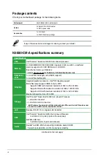
Page 6: ...1 x mini PCIe half length Graphics Integrated graphics processor Intel HD Graphics support Multi VGA output support HDMI D Sub LVDS Supports HDMI with maximum resolution of 3840 x 2160 30Hz Supports D Sub with maximum resolution of 1920 x 1200 60Hz Supports LVDS with maximum resolution of 1920 x 1200 60Hz Maximum shared memory of 512 MB Storage Intel Pentium Quad Core N3050 SoC onboard Processor 1...

Page 7: ...tor 4pin 1 x Chassis Fan connector 4pin 1 x Speaker header 4 1 pin 1 x Front panel audio connector 1 x TPM connector 14 1 pin 1 x LVDS connector 40pin 1 x System Panel connector 1 x Chassis intrusion connector 3 x COM header Connectors for AIO System 1 x 2 pin internal DC power connector 1 x SATA power connector 1 x Stereo speaker connector 1 x DMIC header Connectors for Flat Panel Display 1 x Bac...

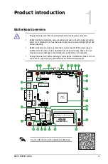
Page 8: ...e power cord before installing or removing the motherboard Failure to do so can cause you physical injury and damage to motherboard components Scan the QR code to get the detailed pin definitions N3050I CM A Super I O WLAN LANGuard LANGuard CLRTC ALC 887VD2 17 0cm 6 7in 17 0cm 6 7in F_PANEL AAFP COM4 J5 COM3 COM2 TPM BLKT_PWR_SEL LAN1 LAN2_USB3_34 ASM 1442K ASM 1480 RTL 8111H RTL 8111H CHA_FAN CPU...

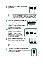
Page 9: ... connect the SATA power cable to this connector PIN 1 12V 12V 12V GND GND GND 5V 5V 5V GND GND GND 3V 3V 3V SATA_PWRCON USB 2 0 connectors USBE5 USBE12 USBE34 Connect the USB module cable to these connectors then install the module to a slot opening at the back of the system chassis These USB connectors comply with USB 2 0 specifications and support up to 480Mbps connection speed USB 5V USB_P1 USB...

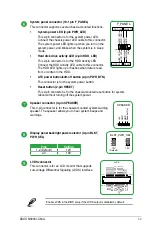
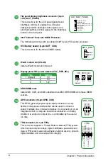
Page 10: ...s mounted reset button for system reboot without turning off the system power Speaker connector 4 pin SPEAKER This 4 pin connector is for the chassis mounted system warning speaker The speaker allows you to hear system beeps and warnings 5V GND GND Speaker Out SPEAKER PIN 1 Display panel backlight power selector 3 pin BLKT_ PWR_SEL Pins Setting 1 2 Default 12V 2 3 19V 1 2 2 3 12V Default 19V BLKT_...

Page 11: ...PWR_SEL Pins Setting 1 Default 3V 2 5V 3 12V 3 12V 2 5V 1 3V Default VCC_PWR_SEL DDR3 DIMM slots Install 2 GB 4 GB and 8 GB unbuffered non ECC DDR3 DIMMs into these DIMM sockets GPIO connector 10 pin GPIO_CON This GPIO general purpose input output connector is a very flexible multi purpose interface that can be used to connect a variety of simple one or two wire devices It is a generic pin on an i...

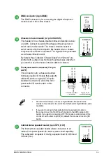
Page 12: ... I O module that supports either HD Audio or legacy AC 97 audio standard Connect one end of the front panel audio I O module cable to this connector AAFP PIN 1 AGND NC SENSE1_RETUR SENSE2_RETUR PORT1 L PORT1 R PORT2 R SENSE_SEND PORT2 L HD audio compliant pin definition PIN 1AGND NC NC NC MIC2 MICPWR Line out_R NC Line out_L Legacy AC 97 compliant definition We recommend that you connect a high de...

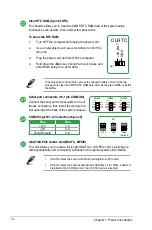
Page 13: ...he battery Serial port connectors 10 1 pin COM2 3 4 Connect the serial port module cable to one of theses connectors then install the module to a slot opening at the back of the system chassis PIN 1 COM4 RXD DTR DSR CTS DCD TXD GND RTS RI PIN 1 COM3 RXD DTR DSR CTS DCD TXD GND RTS RI PIN 1 COM2 RXD DTR DSR CTS DCD TXD GND RTS RI COM4 Ring 5V 12V selection 6 pin J5 Pins Pins 12V 1 2 5V 3 4 Ring Def...

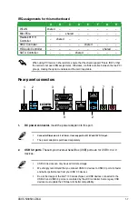
Page 14: ...e design of the Intel 100 series chipset all USB devices connected to the USB 2 0 and USB 3 0 ports are controlled by the xHCI controller Some legacy USB devices must update their firmware for better compatibility IRQ assignments for this motherboard A B C D E F G H WLAN shared Mini PCIe shared Realtek 8111H Controller shared XHCI Controller shared HD Audio Controller shared SATA Controller shared...

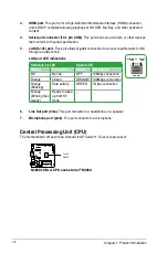
Page 15: ...a network hub LAN port LED indications LAN port Speed LED Activity Link LED 6 Line Out port lime This port connects to a headphone or a speaker 7 Microphone port pink This port connects to a microphone Activity Link LED Speed LED Status Description Status Description Off No link OFF 10Mbps connection Orange Linked ORANGE 100Mbps connection Orange Blinking Data activity GREEN 1Gbps connection Orang...

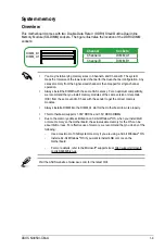
Page 16: ...modules of the same version or data code D C from the same vendor Check with the vendor to get the correct memory modules Always install a DIMM into the DIMM_A1 slot for the motherboard to work properly This motherboard supports 1 35V DDR3L and 1 5V DDR3 DIMMs Due to the memory address limitation on 32 bit Windows OS when you install 4GB or more memory on the motherboard the actual usable memory f...

Page 17: ...1 10 Chapter 1 Product introduction Installing a DIMM 3 To remove a DIMM 3 To install a DIMM ...

Page 18: ... options Using the power button reset button or the Ctrl Alt Del keys to force reset from a running operating system can cause damage to your data or system We recommend you always shut down the system properly from the operating system The BIOS setup screens shown in this section are for reference purposes only and may not exactly match what you see on your screen Visit the ASUS website at www as...

Page 19: ...ged Refer to the Setup Mode item in Boot menu for details The boot device options vary depending on the devices you installed to the system Saves the changes and resets the system Selects the display language of the BIOS setup program Displays the CPU motherboard temperature CPU voltage output CPU chassis fan speed and SATA information Displays the system properties of the selected mode Click Ente...

Page 20: ...rature CPU and memory voltage output Quick Note Advanced Mode The Advanced Mode provides advanced options for experienced end users to configure the BIOS settings The figure below shows an example of the Advanced Mode Refer to the following sections for the detailed configurations To access the EZ Mode click EzMode F7 or press F7 Scroll bar ASUS N3050I CM A 2 3 ...

Page 21: ...nd Exit This option allows you to exit the Setup program without saving your changes When you select this option or if you press Esc a confirmation window appears Select OK to discard changes and exit Launch EFI Shell from USB drives This option allows you to attempt to launch the EFI Shell application shellx64 efi from one of the available USB devices Exit menu The Exit menu items allow you to lo...

Page 22: ...armful interference to radio communications However there is no guarantee that interference will not occur in a particular installation If this equipment does cause harmful interference to radio or television reception which can be determined by turning the equipment off and on the user is encouraged to try to correct the interference by one or more of the following measures Reorient or relocate t...

Page 23: ...a Cet appareil numérique de la Classe B respecte toutes les exigences du Règlement sur le matériel brouilleur du Canada Cet appareil est conforme aux normes CNR exemptes de licence d Industrie Canada Le fonctionnement est soumis aux deux conditions suivantes 1 cet appareil ne doit pas provoquer d interférences et 2 cet appareil doit accepter toute interférence y compris celles susceptibles de prov...

Page 24: ...the highest standards for protecting our environment We believe in providing solutions for you to be able to responsibly recycle our products batteries other components as well as the packaging materials Please go to http csr asus com english Takeback htm for detailed recycling information in different regions Regional notice for California WARNING This product may contain chemicals known to the S...

Page 25: ...ниям и другим соответствующим условиям соответствующих директив Подробную информацию пожалуйста смотрите на www asus com support Български С настоящото ASUSTeK Computer Inc декларира че това устройство е в съответствие със съществените изисквания и другите приложими постановления на свързаните директиви Пълният текст на декларацията за съответствие на ЕС е достъпна на адрес www asus com support Hr...

Page 26: ... America Address 800 Corporate Way Fremont CA 94539 USA Telephone 1 510 739 3777 Fax 1 510 608 4555 Web site http www asus com us Technical Support Support fax 1 812 284 0883 Telephone 1 812 282 2787 Online support http qr asus com techserv ASUS COMPUTER GmbH Germany and Austria Address Harkort Str 21 23 40880 Ratingen Germany Fax 49 2102 959931 Web site http www asus com de Online contact http eu...

Page 27: ...C Directive 2004 108 EC until April 19th 2016 and Directive 2014 30 EU from April 20th 2016 EN 55022 2010 AC 2011 EN 55032 2012 AC 2013 EN 61000 3 2 2014 EN 55013 2001 A1 2003 A2 2006 EN 55024 2010 EN 61000 3 3 2013 EN 55020 2007 A11 2011 R TTE Directive 1999 5 EC EN 300 328 V1 8 1 2012 06 EN 300 440 1 V1 6 1 2010 08 EN 300 440 2 V1 4 1 2010 08 EN 301 511 V9 0 2 2003 03 EN 301 908 1 V6 2 1 2013 04...

Reviews: