background image

P3-P5G43

ASUS PC (Desktop Barebone)

User Manual

Download the latest manual from the ASUS website: www.asus.com

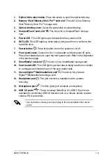
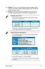
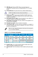
Summary of Contents for P3-P5G43

Page 1: ...P3 P5G43 ASUS PC Desktop Barebone User Manual Download the latest manual from the ASUS website www asus com ...

Page 2: ...RCHANTABILITY OR FITNESS FOR A PARTICULAR PURPOSE IN NO EVENT SHALL ASUS ITS DIRECTORS OFFICERS EMPLOYEES OR AGENTS BE LIABLE FOR ANY INDIRECT SPECIAL INCIDENTAL OR CONSEQUENTIAL DAMAGES INCLUDING DAMAGES FOR LOSS OF PROFITS LOSS OF BUSINESS LOSS OF USE OR DATA INTERRUPTION OF BUSINESS AND THE LIKE EVEN IF ASUS HAS BEEN ADVISED OF THE POSSIBILITY OF SUCH DAMAGES ARISING FROM ANY DEFECT OR ERROR IN...

Page 3: ... 2 3 2 2 3 Utilities menu 2 4 2 2 4 Manual menu 2 5 2 2 5 ASUS contact information 2 6 2 2 6 Other information 2 7 Chapter 3 Motherboard info 3 1 Motherboard overview 3 2 3 2 Jumpers 3 3 3 3 Connectors 3 5 3 3 1 Rear panel connectors 3 5 3 3 2 Internal connectors 3 5 Chapter 4 BIOS setup 4 1 Managing and updating your BIOS 4 2 4 1 1 Creating a bootable floppy disk 4 2 4 1 2 ASUS EZ Flash 2 utility...

Page 4: ...anced menu 4 19 4 4 1 JumperFree Configuration 4 19 4 4 2 CPU Configuration 4 22 4 4 3 Chipset 4 24 2 4 4 Onboard Devices Configuration 4 27 4 4 5 USB Configuration 4 28 4 4 6 PCI PnP 4 29 4 5 Power menu 4 30 4 5 1 Suspend Mode 4 30 2 5 2 ACPI 2 0 Support 4 30 2 5 3 ACPI APIC Support 4 30 4 5 4 APM Configuration 4 31 4 5 5 Hardware Monitor 4 32 4 6 Boot menu 4 33 4 6 1 Boot Device Priority 4 33 4 ...

Page 5: ...ing measures Reorient or relocate the receiving antenna Increase the separation between the equipment and receiver Connect the equipment to an outlet on a circuit different from that to which the receiver is connected Consult the dealer or an experienced radio TV technician for help Canadian Department of Communications Statement This digital apparatus does not exceed the Class B limits for radio ...

Page 6: ...ay from connectors slots sockets and circuitry Avoid dust humidity and temperature extremes Do not place the product in any area where it may become wet Place the product on a stable surface Do not block the air vents on the chassis Always provide proper ventilation for this product We recommend that you use this product in environments with an ambient temperature below 40o C If you encounter tech...

Page 7: ...of the barebone system The chapter lists the system features including introduction on the front and rear panels and internal components 2 Chapter 2 Getting started This chapter helps you power up the system and install drivers and utilities from the support CD 3 Chapter 3 Motherboard info This chapter gives information about the motherboard that comes with the system This chapter includes the mot...

Page 8: ...on to aid in completing a task Where to find more information Refer to the following sources for additional information and for product and software updates 1 ASUS Websites The ASUS websites worldwide provide updated information on ASUS hardware and software products Refer to the ASUS contact information 2 Optional Documentation Your product package may include optional documentation such as warra...

Page 9: ...US P3 P5G43 barebone system with ASUS motherboard 220 W PFC power supply unit 6 in 1 storage card reader 2 Accessories Foot stand and screw 1 pair for vertical placement Rubber stand x 4 for horizontal placement Hard disk drive screw x 8 Optical drive screw x 2 Rubber washer x 8 3 Cables AC power cable Serial ATA signal cable x 2 IDE cable x 1 4 Support CD 5 Quick Installation Guide ...

Page 10: ... ...

Page 11: ...pter 1 System introduction This chapter gives a general description of the barebone system The chapter lists the system features including introduction on the front and rear panels and internal components ...

Page 12: ...2 Extreme CoreTM 2 Duo Pentium Extreme Pentium D Pentium 4 Celeron processors in the 775 land package With audio capabilities extensive connectivity and Fast Ethernet LAN P3 P5G43 is designed for the sophisticated The system s ergonomic design allows vertical or horizontal placement so you can maximize your desktop space 1 2 Front panel The front panel includes the front panel cover connectors pow...

Page 13: ...ader and front panel I O ports Press the indicated area to open the front panel cover Refer to the illustration in the previous page 9 SmartMedia card slot This slot is for a SmartMedia storage card 10 Card reader LED This LED lights up when data is being read from or written to a storage card inserted in any of the card reader slots 11 Secure Digital MultimediaCard slot This slot is for a Secure ...

Page 14: ...r other audio sources 9 Metal bracket lock Secures the expansion slot card metal brackets 10 Voltage selector Allows you to adjust the system input voltage according to the voltage supply in your area If the voltage supply in your area is 100 127 V set the switch to 115 V If the voltage supply in your area is 200 240 V set the switch to 230 V Setting the switch to 115 V in a 230 V environment will...

Page 15: ... D Sub During POST only the monitor connected to the D Sub port has display The dual display function works only under Windows Playback of HD DVD and Blu Ray Discs For better playback quality we recommend that you follow the system requirements listed below Suggested list CPU AMD Athlon 4400 DIMM DDR2 800 1GB or higher BIOS setup Frame Buffer Size 256MB or higher Playback software CyberLink PowerD...

Page 16: ... Serial Bus 2 0 USB 2 0 ports are available for connecting USB 2 0 devices such as a mouse printer scanner camera PDA and others 18 Rear Speaker Out port black This port connects the rear speakers in a 4 channel 6 channel or 8 channel audio configuration 19 Side Speaker Out port gray This port connects the side speakers in an 8 channel audio configuration 20 Microphone port pink This port connects...

Page 17: ...The installed components are labeled for your reference 1 5 25 inch empty optical drive bay 2 Front panel assembly 3 Optical drive lock 4 Hard disk drive bays 5 Hard disk drive lock 6 Power supply unit 7 PCI slots 8 PCI Express x16 slot 9 PCI Express x1 slot 10 ASUS motherboard 11 Metal bracket lock 12 LGA775 socket 13 DIMM sockets R 1 3 7 5 8 2 6 4 11 9 12 13 10 ...

Page 18: ...1 8 Chapter 1 System introduction ...

Page 19: ...Chapter 2 Getting started This chapter helps you to power up the system and install drivers and utilities from the support CD ...

Page 20: ... software applications and utilities that you can install to avail all motherboard features 2 2 1 Running the support CD Place the support CD to the optical drive The CD automatically displays the Drivers menu if Autorun is enabled in your computer Motherboard settings and hardware options vary Use the setup procedures presented in this chapter for reference only Refer to your OS documentation for...

Page 21: ...rton Internet Security 2008 Installs the Norton Internet Security 2008 Realtek Audio Driver Install the Realtek Audio Driver Intel R Chipset Inf Update Program Installs the Intel chipset Inf update program Intel R Graphics Accelerator Driver Installs the Intel graphics accelerator driver Realtek RTL8111B C 10 100 1000M LAN Driver Installs the Realtek RTL8111B C 10 100 1000M LAN driver Marvell 61xx...

Page 22: ...Internet connection so that you can connect to the ASUS website Realtek Diagnostics Utility Installs the Realtek Diagnostics Utility ASUS AI Manager Installs the ASUS AI Manager Adobe Reader 8 Installs the Adobe Reader 8 that allows you to open view and print documents in Portable Document Format PDF ASUS Express Gate Installer Installs the ASUS Express Gate application 2 2 3 Utilities menu The Ut...

Page 23: ...nuals Click an item to open the folder of the user manual FarStone Utility Installs the FarStone Utility ASUS Screen Saver Installs the ASUS screensaver Most user manual files are in Portable Document Format PDF Install the Adobe Reader from the Utilities menu before opening a user manual file ...

Page 24: ...2 6 Chapter 2 Getting started 2 2 5 ASUS contact information Click the Contact tab to display the ASUS contact information ...

Page 25: ...rmation on the motherboard and the contents of the support CD Click an icon to display the specified information Motherboard Info Displays the general specifications of the motherboard P3 P5G43 P3 P5G43 0306 09 19 2008 ASUSTeK Computer INC x xx American Megatrends Inc 1024 KB BIOS ROM Size BIOS Release Date BIOS Version Vendor Version Product Name Manuafacture BIOS Motherboard ...

Page 26: ...d Technical support Form Displays the ASUS Technical Support Request Form that you have to fill out when requesting technical support Filelist Displays the contents of the support CD and a brief description of each in text format ...

Page 27: ...Motherboard info Chapter 3 This chapter gives information about the motherboard that comes with the system This chapter includes the motherboard layout jumper settings and connector locations ...

Page 28: ...12 USBPW78 USB78 PS2_USBPW5 6 USBPW1 4 8Mb BIOS Super I O CR2032 3V Lithium Cell CMOS Power 24 4cm 9 6in PS 2KBMS USB56 RTL 81111C LGA775 CPU_FAN Intel ICH10 Marvell 6111B2 Intel G43 SATA12 CLRTC SB_PWR CD DDR2 DIMM_A1 64 bit 240 pin module DDR2 DIMM_A2 64 bit 240 pin module DDR2 DIMM_B1 64 bit 240 pin module DDR2 DIMM_B2 64 bit 240 pin module PANEL JMB381 PRI_EIDE RTM870T 954 ALC1200 AAFP SPDIF_O...

Page 29: ...ins 2 3 for about 5 10 seconds then move the cap back to pins 1 2 3 Plug the power cord and turn ON the computer 4 Hold down the Del key during the boot process and enter BIOS setup to re enter data Except when clearing the RTC RAM never remove the cap on CLRTC jumper default position Removing the cap will cause system boot failure If the steps above do not help remove the onboard battery and move...

Page 30: ...nd S4 modes no power to CPU DRAM in slow refresh power supply in reduced power mode The USB device wake up feature requires a power supply that can provide 500mA on the 5VSB lead for each USB port otherwise the system would not power up The total current consumed must NOT exceed the power supply capability 5VSB whether under normal condition or in sleep mode USB Device Wake Up R 3 2 2 1 USBPW1 4 5...

Page 31: ...w digital sound output Connect one end of the S PDIF audio cable to this connector and the other end to the S PDIF module The S PDIF out module is purchased separately Digital Audio Connector R 5V SPDIFOUT GND SPDIF_OUT 2 Optical drive audio connector 4 pin CD These connectors allow you to receive stereo audio input from sound sources such as a CD ROM TV tuner or MPEG card Internal Audio Connector...

Page 32: ...nnectors on each Ultra DMA 133 100 66 33 signal cable blue black and gray Connect the blue connector to the motherboard s IDE connector then select one of the following modes to configure your device Drive jumper setting Mode of device s Cable connector Single device Cable Select or Master Black Two devices Cable Select Master Black Slave Gray Master Master Black or gray Slave Slave IDE Connector ...

Page 33: ...t a SATA device Connect the Right angle side of the SATA cable to SATA1 connector and the other side to a SATA device Connect the Straight out side of the SATA cable to SATA2 connector and the other side to a SATA device Right angle side SATA Connectors R GND RSATA_TXP1 RSATA_TXN1 GND RSATA_RXP1 RSATA_RXN1 GND SATA1 GND RSATA_TXP2 RSATA_TXN2 GND RSATA_RXP2 RSATA_RXN2 GND SATA2 Straight out side ...

Page 34: ...assis These USB connectors comply with USB 2 0 specification that supports up to 480 Mbps connection speed Never connect a 1394 cable to the USB connectors Doing so will damage the motherboard R USB 2 0 Connectors USB78 USB 5V USB_P8 USB_P8 GND NC USB 5V USB_P7 USB_P7 GND 1 USB910 USB 5V USB_P10 USB_P10 GND NC USB 5V USB_P9 USB_P9 GND 1 USB1112 USB 5V USB_P12 USB_P12 GND NC USB 5V USB_P11 USB_P11 ...

Page 35: ...making sure that the black wire of each cable matches the ground pin of the connector Do not forget to connect the fan cables to the fan connectors Insufficient air flow inside the system may damage the motherboard components These are not jumpers Do not place jumper caps on the fan connectors Only the CPU FAN connector support the ASUS Advanced Q Fan feature Fan Connectors R CPU_FAN GND CPU FAN P...

Page 36: ...o HD Audio If you want to connect a High Definition front panel audio module to this connector set the Front Panel Support Type item in the BIOS to HD Audio See section 4 4 3 Chipset for details 7 Chassis intrusion connector 4 1 pin CHASSIS This connector is for a chassis mounted intrusion detection sensor or switch Connect one end of the chassis intrusion sensor or switch cable to this connector ...

Page 37: ... if the power is inadequate The ATX 12 V Specification 2 0 compliant 400W PSU has been tested to support the motherboard power requirements 9 ATX power connectors 24 pin EATXPWR 4 pin ATX12V These connectors are for ATX power supply plugs The power supply plugs are designed to fit these connectors in only one orientation Find the proper orientation and push down firmly until the connectors complet...

Page 38: ... 2 pin connector is for the HDD Activity LED Connect the HDD Activity LED cable to this connector The IDE LED lights up or flashes when data is read from or written to the HDD System warning speaker 4 pin SPEAKER The 4 pin connector is for the chasiss mounted system warning speaker The speaker allows you to hear system beeps and warnings ATX power button soft off button 2 pin PWRSW This connector ...

Page 39: ...ASUS P3 P5G43 This chapter tells how to change the system settings through the BIOS Setup menus Detailed descriptions of the BIOS parameters are also provided Chapter 4 BIOS setup ...

Page 40: ...ities 4 1 1 Creating a bootable floppy disk 1 Do either of the following to create a bootable floppy disk DOS environment a Insert a 1 44MB floppy disk into the drive b At the DOS prompt type format A S then press Enter Save a copy of the original motherboard BIOS file to a bootable floppy disk or a USB flash disk in case you need to restore the BIOS in the future Copy the original motherboard BIO...

Page 41: ... disk drive b Click from the Windows desktop then select Computer c Right click Floppy Disk Drive then click Format to display the Format 3 1 2 Floppy dialog box d Select the Create an MS DOS startup disk check box e Click Start 2 Copy the original or the latest motherboard BIOS file to the bootable floppy disk ...

Page 42: ...OST To update the BIOS using EZ Flash 2 1 Visit the ASUS website www asus com to download the latest BIOS file for the motherboard 2 Save the BIOS file to a floppy disk or a USB flash disk then restart the system 3 You can launch the EZ Flash 2 in two ways 1 Insert the floppy disk USB flash disk that contains the BIOS file to the floppy disk drive or the USB port Press Alt F2 during POST to displa...

Page 43: ...s o filename where the filename is any user assigned filename not more than eight alphanumeric characters for the main filename and three alphanumeric characters for the extension name Main filename Extension name A afudos oOLDBIOS1 rom Ensure that the floppy disk is not write protected and has at least 1 2MB free space to save the file The succeeding BIOS screens are for reference only The actual...

Page 44: ...mpt after the BIOS update process is completed Reboot the system from the hard disk drive A afudos iP3P5G43 ROM AMI Firmware Update Utility Version 1 19 ASUS V2 07 03 11 24BB Copyright C 2002 American Megatrends Inc All rights reserved WARNING Do not turn off power during flash BIOS Reading file done Reading flash done Advance Check Erasing flash done Writing flash done Verifying flash done Please...

Page 45: ...B flash disk to P3P5G43 ROM Recovering the BIOS from a floppy disk To recover the BIOS from a floppy disk 1 Turn on the system 2 Insert the floppy disk with the original or updated BIOS file to the floppy disk drive 3 The utility displays the following message and automatically checks the floppy disk for the original or updated BIOS file Bad BIOS checksum Starting BIOS recovery Checking for floppy...

Page 46: ...arting BIOS recovery Checking for floppy 4 Restart the system after the utility completes the updating process The recovered BIOS may not be the latest BIOS version for this motherboard Visit the ASUS website www asus com to download the latest BIOS file Only the USB flash disk with FAT 32 16 format and single partition can support ASUS CrashFree BIOS 3 The device size should be smaller than 8GB D...

Page 47: ...to manage save and update the motherboard BIOS in Windows environment The ASUS Update utility allows you to Save the current BIOS file Download the latest BIOS file from the Internet Update the BIOS from an updated BIOS file Update the BIOS directly from the Internet and View the BIOS version information This utility is available in the support DVD that comes with the motherboard package ASUS Upda...

Page 48: ...Next Updating the BIOS through the Internet To update the BIOS through the Internet 1 Launch the ASUS Update utility from the Windows desktop by clicking Start Programs ASUS ASUSUpdate ASUSUpdate The ASUS Update main window appears 2 Select Update BIOS from the Internet option from the drop down menu then click Next ...

Page 49: ... a file option from the drop down menu then click Next 4 From the FTP site select the BIOS version that you wish to download Click Next 5 Follow the screen instructions to complete the update process The ASUS Update utility is capable of updating itself through the Internet Always update the utility to avail all its features 3 Locate the BIOS file from the Open window then click Open 4 Follow the ...

Page 50: ...ou can enable the security password feature or change the power management settings This requires you to reconfigure your system using the BIOS Setup program so that the computer can recognize these changes and record them in the CMOS RAM of the SPI chip The firmware chip on the motherboard stores the Setup utility When you start up the computer the system provides you with the opportunity to run ...

Page 51: ...lect an item on the menu bar press the right or left arrow key on the keyboard until the desired item is highlighted Some of the navigation keys differ from one screen to another 4 2 3 Navigation keys At the bottom right corner of a menu screen are the navigation keys for that particular menu Use the navigation keys to select items in the menu and change the settings Navigation keys Sub menu items...

Page 52: ...ield is enclosed in brackets and is highlighted when selected To change the value of a field select it then press Enter to display a list of options Refer to 4 2 7 Pop up window 4 2 7 Pop up window Select a menu item then press Enter to display a pop up window with the configuration options for that item 4 2 8 Scroll bar A scroll bar appears on the right side of a menu screen when there are items ...

Page 53: ...1 BIOS menu screen for information on the menu screen items and how to navigate through them Select Screen Select Item Change Field Tab Select Field F1 General Help F10 Save and Exit ESC Exit v02 58 C Copyright 1985 2008 American Megatrends Inc BIOS SETUP UTILITY Main Advanced Power Boot Tools Exit Use ENTER TAB or SHIFT TAB to select a field Use or to configure system Time System Time 19 34 30 Sy...

Page 54: ...iguration options Not Installed Auto CDROM ARMD LBA Large Mode Auto Enables or disables the LBA mode Setting to Auto enables the LBA mode if the device supports this mode and if the device was not previously formatted with LBA mode disabled Configuration options Disabled Auto Block Multi Sector Transfer M Auto Enables or disables data multi sectors transfers When set to Auto the data transfer from...

Page 55: ... Configure SATA as IDE Sets the configuration for the Serial ATA connectors supported by the Southbridge chip Configuration options IDE AHCI 4 3 4 Storage Configuration The items in this menu allow you to set or change the configurations for the SATA devices installed in the system Select an item then press Enter if you want to configure the item SATA Configuration SATA Configuration Enhanced Conf...

Page 56: ...formation Processor Displays the auto detected CPU specification System Memory Displays the auto detected system memory BIOS Information Version 0306 Build Date 09 19 08 Processor Type Intel R Core TM 2 CPU 6300 1 86GHz Speed 1866MHz Count 2 System Memory Installed Size 1024MB Usable Size 990MB IDE Detect Time Out Sec 35 Selects the time out value for detecting ATA ATAPI devices Configuration opti...

Page 57: ...et CPU frequency and the relevant parameters will be auto adjusted Frequencies higher than CPU manufacturer recommends are not guaranteed to be stable If the system becomes unstable return to the default v02 58 C Copyright 1985 2008 American Megatrends Inc BIOS SETUP UTILITY Main Advanced Power Boot Tools Exit JumperFree Configuration CPU Configuration Chipset Onboard Devices Configuration USB Con...

Page 58: ...values range from 133 to 600 Refer to the table below for the correct Front Side Bus and CPU External Frequency settings Overclock Options Overclock 5 Allows you to select the overclock options Configuration options Overclock 5 Overclock 10 Overclock 15 Overclock 20 Overclock 30 The following item appears only when you set the AI Overclocking item to Overclock Profile Front Side Bus CPU External F...

Page 59: ... v The following table shows the DRAM Frequency options that appear when the FSB value is 1333 1066 and 800 DRAM Frequency Auto Allows you to set the DDR2 operating frequency Configuration options Auto 667 MHz 800 MHz 1067MHz CPU Voltage Auto Allows you to set the CPU VCore voltage The values range from 0 8500V to 1 55V with a 0 00625V interval Configuration options Auto Setting a very high voltag...

Page 60: ...for legacy operating system such as Windows NT4 0 Default Disabled Configuration options Disabled Enabled v02 58 C Copyright 1985 2008 American Megatrends Inc Configure advanced CPU settings Module Version 3D 06 Manufacturer Intel Brand String Intel R Core TM 2 CPU 6300 1 86GHz Frequency 1 86GHz FSB Speed 1066MHz Cache L1 64 KB Cache L2 2048 KB Ratio Status Unlocked Max 07 0 Min 06 0 Ratio Actual ...

Page 61: ...el Virtualization Technology allows a platform to run multiple operating systems and applications in independent partitons With virtualization one computer system can function as multiple virtual systems Configuration options Enabled Disabled CPU TM function Enabled Enables or disables Intel CPU Thermal Monitor TM function a CPU overheating protection function When enabled the CPU core frequency a...

Page 62: ...cs Mode Select Enabled 32MB GTT Graphics Memory Size No VT mode 2MB DVMT Mode Select DVMT Mode DVMT Memory 256MB Protect Audio Video Path Mode Lite Options 128MB 256MB Options Memory Remap Feature Disabled Allows you to enable or disable the remapping of overlapped PCI memory above the total physical memory We recommend that you set this item to Enabled when you install 4GB memory Configuration op...

Page 63: ...ite or Paranoid If you select Paranoid Mode the system reserves 96MB for playing and storing the decrypted contents The operation system and other programs cannot use this reserved memory and Vista Aero DWM is disabled This option only appears when installing 1GB DDR2 DIMMs into the DIMM sockets Feature PAVP Lite PAVP Paranoid Compressed video buffer is encrypted Yes Yes HW 128 bit AES decryption ...

Page 64: ...he front panel support type If High Definition Audio Front Panel used please set HD Audio mode Configuration options AC97 HD Audio SPDIF_OUT Mode Setting SPDIF Output Allows you to select SPDIF_OUT mode setting Configuration options HDMI Output SPDIF Output Options South Bridge Chipset Configuration Audio Controller Enabled Front Panel Type HD Audio SPDIF_OUT Mode Setting SPDIF Output Options Enab...

Page 65: ...ars only when the Onboard LAN item is set to Enabled Configuration options Disabled Enabled Marvell IDE controller Enabled Allows you to enable or disable Marvell IDE controller Configuration options Enabled Disabled 1394 controller Enabled Allows you to enable or disable 1394 controller Configuration options Enabled Disabled Onboard Device Configuration Onboard LAN Enabled LAN Option ROM Disabled...

Page 66: ...isable or select the different values of the USB functions Configuration options Disabled Enabled USB 2 0 Controller Enabled Allows you to enable or disable USB 2 0 controller Configuration options Enabled Disabled Legacy USB Support Auto Allows you to enable or disable support for Legacy USB storage devices including USB flash drives and USB hard drives Setting to Auto allows the system to detect...

Page 67: ...e system When set to Yes and if you install a Plug and Play operating system the operating system configures the Plug and Play devices not required for boot Configuration options No Yes Select Screen Select Item Change Option F1 General Help F10 Save and Exit ESC Exit v02 58 C Copyright 1985 2008 American Megatrends Inc BIOS SETUP UTILITY Advanced Advanced PCI PnP Settings WARNING Setting wrong va...

Page 68: ...ss power than in the S1 state When signaled by a wake up device or event the system resumes to its working state exactly where it was left off Auto Detected by OS 2 5 2 ACPI 2 0 Support Disabled Allows you to add more tables for Advanced Configuration and Power Interface ACPI 2 0 specifications Configuration options Disabled Enabled 2 5 3 ACPI APIC Support Enabled Allows you to enable or disable t...

Page 69: ...feature requires an ATX power supply that provides at least 1A on the 5VSB lead Configuration options Disabled Enabled Resume On Ring Disabled Allows you to enable or disable RI to generate a wake event Configuration options Disabled Enabled Resume On PCI Devices Disabled When set to Enabled this parameter allows you to wake the system through a PCI LAN or modem card This feature requires an ATX p...

Page 70: ...led Chassis Fan Speed Ignored or N A The onboard hardware monitor automatically detects and displays the Chassis fan speed in rotations per minute RPM If the fan is not connected to the motherboard the field shows N A Select Ignored if you do not wish to display the detected speed Chassis Q Fan Control Disabled Allows you to enable or disable the Chassis Q Fan control Configuration options Disable...

Page 71: ...LOPPY DRIVE 2nd Boot Device Hard Drive 3rd Boot Device ATAPI CD ROM Specifies the boot sequence from the available devices BIOS SETUP UTILITY Main Advanced Power Boot Tools Exit Select Screen Select Item Enter Go to Sub Screen F1 General Help F10 Save and Exit ESC Exit v02 58 C Copyright 1985 2008 American Megatrends Inc Boot Settings Configuration Security Specifies the Boot Device Priority seque...

Page 72: ... the time needed to boot the system When set to Disabled BIOS performs all the POST items Configuration options Disabled Enabled Full Screen Logo Enabled This allows you to enable or disable the full screen logo display feature Configuration options Disabled Enabled AddOn ROM Display Mode Force BIOS Allows you to set display mode for Option ROM Configuration options Force BIOS Keep Current Bootup ...

Page 73: ...r again to disabled password Change Supervisor Password Select this item to set or change the supervisor password The Supervisor Password item on top of the screen shows the default Not Installed After you set a password this item shows Installed To set a Supervisor Password 1 Select the Change Supervisor Password item and press Enter 2 From the password box type a password composed of at least si...

Page 74: ...ct the Change User Password item and press Enter 2 On the password box that appears type a password composed of at least six letters and or numbers then press Enter 3 Confirm the password when prompted The message Password Installed appears after you set your password successfully To change the user password follow the same steps as in setting a user password Clear User Password Select this item t...

Page 75: ...tility V3 25 Current ROM Update ROM A Note Enter Select or Load Tab Switch V Drive Info Up Down Home End Move B Backup ESC Exit FLASH TYPE MXIC 25L8005 PATH A BOARD P5QL EM P3 P5G43 VER 0306 H 00 B 02 DATE 09 19 2008 BOARD Unknown VER Unknown DATE Unknown Select Screen Select Item Change Field Enter Go to Sub Screen F1 General Help F10 Save and Exit ESC Exit v02 58 C Copyright 1985 2008 American M...

Page 76: ...ration options Prompt User 1 second 3 seconds 5 seconds 10 seconds 15 seconds 20 seconds 30 seconds Reset User Data No Allows you to clear Express Gate s user data Configuration options No Reset When setting this item to Reset make sure to save the setting to the BIOS so that the user data will be cleared the next time you enter the Express Gate User data includes the Express Gate s settings as we...

Page 77: ...Exit AI NET 2 Pair Status Length Check Realtek LAN cable Disabled Check Realtek LAN cable during POST It will take 3 to 10 seconds to diagnose LAN cable Check Realtek LAN cable Disabled Enables or disables checking of the Realtek LAN cable during the Power On Self Test POST Configuration options Disabled Enabled ...

Page 78: ...oose this option from the Exit menu to ensure the values you selected are saved to the CMOS RAM An onboard backup battery sustains the CMOS RAM so it stays on even when the PC is turned off When you select this option a confirmation window appears Select OK to save changes and exit 4 8 Exit menu The Exit menu items allow you to load the optimal or failsafe default values for the BIOS items and sav...

Reviews: